12. Machine Week (CLS Students Group 2)
This group consisted of Alaric, Aaron, Jack, and Jada.
Slide
Long Video
Short Video
Files
All design files can be found here
All code files can be found here
Inspiration
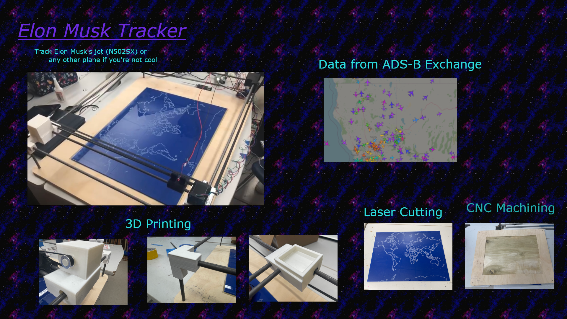
Our group had a difficult time designing an idea because we wanted to incorporate many different concepts. We eventually decided to create an Elon Musk Plane tracker. There was a big news story on twitter about user Jack Sweeney posting information on Elon Musk’s personal plane on twitter. The idea was to use this information along with an x/y gantry to pinpoint his exactly location on a laser engraved world.
Initial Plan
The group stated visualizing how to make the machine. Looking at the machines in the lab they realized that the plane tracker had to operate similarly to the Shopbot in the lab. Our machine needed to be a 2-axis gantry using 2 stepper motors. Using Fusion 360 Jack began designing a full design that we would need. All of the motor mounts and connectors were initially their as place holders and the group would later edit them to resemble the final design.
Below shows the 3d model that Jack made.
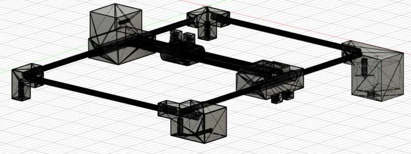
The plan was to create a wood base where the map would be engraved into. The gantry would be elevated using metal rods on the four corners of the bed with 3D printed pieces to connect the elevated corners. The rods connecting each of the four corners of the X-axis and Y-axis would have to correspond to the design of the map. Along the X axis their would have to be a stepper motor with a belt to connected to the other side for accurate movmement of the axis similar to a 3D printer. In the middle of the belt would have to be an X-axis 3D printed piece that would travel with the belt, have a bearing for easy movement and would connect to the other side of the machine that would also have a bearing. Connected to that X-axis piece would be a stepper motor to move the a Y-axis 3D printed piece along a belt connected to the other side of the machine. The Y-axis piece would also have a bearing for easy movement. In the middle of the Y-axis piece would be the laser. The machine would opperate by moving the X-axis first to position the Y-axis, then the Y-axis piece would move to position the laser at the exact place where Elon Musks plane was.
The group discussed and found out that they were going to need the following items
- Raspberry Pi for plane API
- 2 Stepper Motors
- 2 L298N Motor Driver
- 1/8 in wood to engrave the map on
- 1/2 in wood for the base that all of the materials would be placed on the
- Bearings
- Metal Rods
- 5V 10A power adapter for motor drivers
- 5V power adapter for raspberry pi
- 1 Laser
- 4.99k Ohm resistor for Laser
- LOTS and LOTS of wires
The group broke up the design into the steps below
- Laser cut the map- Aaron
- Aquire plane data using API - Jack and Alaric
- Getting the stepper motors functioning with Raspberry Pi - Jada, Aaron, and Alaric
- Finding a way to convert Longitue and Latitude coordinates to x and y coordinates - Aaron and Alaric
- Connecting the API, the X and Y converter, and the stepper motors to know exactly how many steps needed to get to a location using Raspberry Pi. - Alaric
- Designing 3D connecters and axis pieces, keeping in mind the dimentions of the bearings and metal rods - Jack, Alaric, Jada, and Aaron
- Cutting the steel rods - Jack, Jada, Alaric and Aaron
- Filing out the 3D designs so the rods fit into the prints - Jack
- Designing Shopbot file and CNCing the wood base, keeping in mind the dimentions of the final design - Alaric, Aaron, and Jada
- Creating a board to power the stepper motor drivers, and the laser while also sharing a common ground with the Rasperry Pi, drivers, laser, and power sources - Jada, Aaron, and Jack
- Connecting everything together - Alaric, Aaron, and Jack
- Creating video and slideshow - Jada
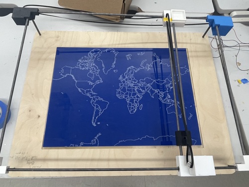
Laser Map
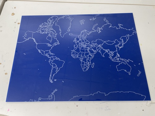
To begin Aaron worked on getting the right map SVG for the gantry. Even though the assignment seemed simple this would be a critical part of the machine because the map needs to be to scale and the machine would be based off its size. He stared looking around for different usable SVG’s and came accross this one.

He went to print this image and thought the job was finished. A couple of days later when the Alaric Pan and Aaron Logan were doing reaserch on how to convert longitude and latitude to x and y coordinates, they realized that they would need a mercator map. A mercator map is the most accurate way to locate a point using longitude and latitude coordinates.
He searched and found this SVG

He went to laser this out on a piece of cardboard and the design was finished
Plane API
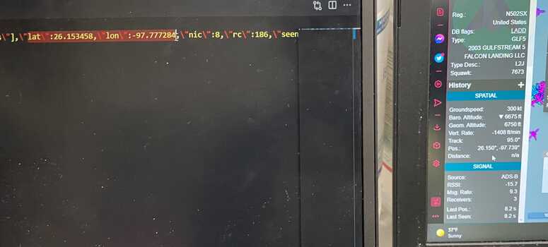
Alaric and Jack worked on this aspect because they had some previous experience with Raspberry Pi and APIs. The twitter API was something that Jack had used before and was ready to use the data that Jack Sweeney posts on his account but came accross a problem. The machine would be dependent on the availability of the twitter posts. If there wasn’t a post then the machine wouldn’t work until there was. To troubleshoot this, they decided to go right to the site being used which was adsb exchange, which later Jack Sweeney would also recommend after they asked for advice.
The website had a nice interface and could track any airplane if the user knew the plane ID.
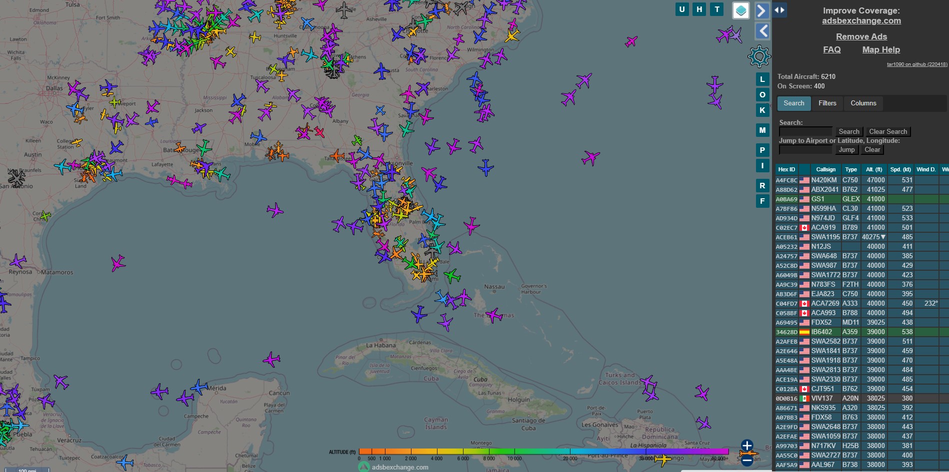
Knowing that Elon Musks plane had an ID of N502SX they could track the plane on the site.
Alaric started off trying to use rapid api and used the following code after making a rapid api account and getting a key:
import requests

url = "https://adsbexchange-com1.p.rapidapi.com/v2/registration/N8737L/"

headers = {
    "X-RapidAPI-Host": "adsbexchange-com1.p.rapidapi.com",
    "X-RapidAPI-Key": "insert key"
}

response = requests.request("GET", url, headers=headers)

print(response.text)
This, however, did not work since buying access to the ads-b exchange api is necessary for usage with rapid api, so Jack and Alaric tried to find another way to use the api.
They found the official site for the eds-g exchange api with some example code and used it directly with the following code after running wmic path win32_computersystemproduct get uuid in the command line to get the uuid.
import requests
import json

url = "https://adsbexchange.com/api/aircraft/call/N502SX/"

headers = {
    'api-auth': 'insert uuid'
}

response = requests.get(url, headers=headers)

with open("test.json", "w") as f:
    json.dump(response.text, f)
This produced a json file, but since they did not have a key for the api, they could not get the actual information, and the json file was just filled with default values for all the data. Jack then contacted ads-b exchange to try to get a free key since the project is not for profit. They, however, never responded, so they just bought access to the rapid api support for ads-b exchange, and it worked with the following code:
import requests
import json

url = "https://adsbexchange-com1.p.rapidapi.com/v2/callsign/N502SX/"

headers = {
    "X-RapidAPI-Host": "adsbexchange-com1.p.rapidapi.com",
    "X-RapidAPI-Key": "27d6e0192emsh0b0d9c0364793c1p175136jsn803c2abbbc60"
}

response = requests.get(url, headers=headers)

with open("test.json", "w") as f:
    json.dump(response.text, f)
They then added the following code to the above to parse through and specifically find the latitude and longitude.
data = response.text
lat, lon = 0.0, 0.0
for i in range(len(data)):
if data[i: i + 6] == '"lat":':
lenNum = 1
while data[i + lenNum] != ',':
lenNum += 1
lat = float(data[i + 6: i + lenNum])
elif data[i: i + 6] == '"lon":':
lenNum = 1
while data[i + lenNum] != ',':
lenNum += 1
lon = float(data[i + 6: i + lenNum])
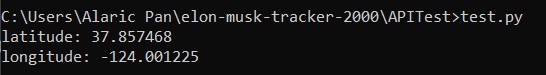
print("latitude: " + str(lat))
print("longitude: " + str(lon))
Musk’s plane wasn’t flying at the time of testing, so we used a different plane and got the following output:
Making the Stepper Motors Run
Aaron and Jada decided to work on this part because they wanted to learn more about steppers and how they function, while also learning how to use the Raspberry Pi GPIOs. Their were numerous Youtube videos on how to use the stepper motors with different drivers. They initally decided to use a DRV8825 with the help of this youtube video. The reason they initally choose this driver was because it allowed for easier control of stepper motors specifically. The driver only had two inputs, the direction and the amount of steps. However, they weren’t able to get this to work for this reason
The driver uses VIR and required the voltage to be set with a screwdriver, but the voltage couldn’t go low enough. According to the video the VIR should be half of the amperage of the Stepper motor being used. They were using a Longruner Nema and looking at the data sheet it requires 1.7 amps. The VIR there for had to be set to a value of .85V but the VIR capped out at 1.3V.
They tried to ignore this and hoping that it wouldn’t be a significant difference from the intended value. With the driver set at 1.3V, and everything plugged in, they ran the program but nothing moved, their was only a faint noise coming from the motor so Aaron went to touch the driver and shocked himself. He wasn’t hurt at all but still talked it with his instructors about what happened and made sure to take note of this experience. This was the last straw and they decided to switch drivers.
Aaron and Jada decided that the next best option was to use a L298N Motor Driver. Alaric Pan had used these before for his output week and already had the configurations set for an Arduino. Aaron and Jada proceeded to code the stepper using a Raspberry Pi 2 Model B.
Aaron had a small bit of experice because of his work with the Jetson Nano from emedded programming week and this was brand new to Jada so she got to learn more while working alongside Aaron. Using the Youtube video and websites listed below, they began working. Aaron and Jada had to operate the Rasperry Pi and it began with flashing a new OS onto the SD Card, they used this youtube video. After what seemed like hours they were able to get it to work.
Converting Longitude and Latitude to x and y
This part Aaron, Alaric amd Jada worked on. They searched the internet for some equation or converter that would be able to convert the desire location to x and y. They came accross this stack overflow site
Aaron noted this line of code at the bottom of the site created by user 武状元 Woa
import math
from numpy import log as ln

# Define the size of map
mapWidth    = 200
mapHeight   = 100


def convert(latitude, longitude):
    # get x value
    x = (longitude + 180) * (mapWidth / 360)

    # convert from degrees to radians
    latRad = (latitude * math.pi) / 180

    # get y value
    mercN = ln(math.tan((math.pi / 4) + (latRad / 2)))
    y     = (mapHeight / 2) - (mapWidth * mercN / (2 * math.pi))

    return x, y

print(convert(41.145556, 121.2322))
This code was AMAZING it was two simple inputs, the size of the map and the longitude and latitude. They tested the code by using the coordinates of (0,0) on a psudo 12 x 24 in map and the value came back with (6,12) whcih is exacly the middle of the map.
They the tried to use this code on the map that Aaron had made earlier and realized one thing, they didn’t know whether the y value was from the top of the map or bottom of the map. They inputted a negative value for the latitude and received a value greater than half of the map size, meaing the y was in refernce to the top of the map.
They tried to test (0,0) on their map and realized that their was an offset. Because of the map Aaron had printed their was a 1.5 in offset for the y-value, even thought the map looked semetrical. After fixing this problem they were finished.
All marks made on the map are circled in red to make it more visible.
To make sure everything was working They both went to the Rasberry Pi 2 Model B, installed the libraries, and ran the code; it was successful.
Final Code
Alaric put everything together in the final code and split it between 3 files.
apiData.py
This had functions involving getting raw data from the api and converting it from latitude longitude to inches on the map.
import requests
import math
from numpy import log as ln

def get_lat_lon(callsign='N502SX'):
    # uses the api to get the latitude and longitude and returns a list of 2 ints
    url = 'https://adsbexchange-com1.p.rapidapi.com/v2/callsign/' + callsign + '/'
    headers = {
        "X-RapidAPI-Host": "adsbexchange-com1.p.rapidapi.com",
        "X-RapidAPI-Key": "27d6e0192emsh0b0d9c0364793c1p175136jsn803c2abbbc60"
    }
    response = requests.get(url, headers=headers)
    data = response.text

    lat, lon = 0.0, 0.0
    flying = False

    for i in range(len(data)):
        if data[i: i + 6] == '"lat":':
            lenNum = 1
            while data[i + lenNum] != ',':
                lenNum += 1
            lat = float(data[i + 6: i + lenNum])
            flying = True
        elif data[i: i + 6] == '"lon":':
            lenNum = 1
            while data[i + lenNum] != ',':
                lenNum += 1
            lon = float(data[i + 6: i + lenNum])
            flying = True

    return [lon, lat], flying

def lat_lon_to_xy(pos):
# Define the size of map
    mapWidth    = 584.2
    mapHeight   = 431.8


    # get x value
    x = (pos[0] + 180) * (mapWidth / 360)

    # convert from degrees to radians
    latRad = (pos[1] * math.pi) / 180

    # get y value
    mercN = ln(math.tan((math.pi / 4) + (latRad / 2)))
    y     = (mapHeight / 2) - (mapWidth * mercN / (2 * math.pi))

    return [x, mapHeight-y] # mapHeight - y makes the origin point from the bottom left corner for the latitude
stepper.py
This had a class for the stepper motor that used a combination of code from Alaric’s outputs week (converted from arduino to python of course) and work from Aaron and Jada.
import RPi.GPIO as GPIO
from time import sleep

class Stepper():
    def __init__(self, chan, delayTime):
        self.chan = chan
        self.delayTime = delayTime
        self.phase = 0

    def run_step(self):
        if self.phase == 0:
            GPIO.output(self.chan, (GPIO.HIGH, GPIO.LOW, GPIO.HIGH, GPIO.LOW))
        elif self.phase == 1:
            GPIO.output(self.chan, (GPIO.LOW, GPIO.HIGH, GPIO.HIGH, GPIO.LOW))
        elif self.phase == 2:
            GPIO.output(self.chan, (GPIO.LOW, GPIO.HIGH, GPIO.LOW, GPIO.HIGH))
        elif self.phase == 3:
            GPIO.output(self.chan, (GPIO.HIGH, GPIO.LOW, GPIO.LOW, GPIO.HIGH))
        sleep(self.delayTime)

    def step_cw(self, num_steps):
        for i in range(num_steps):
            self.phase = (self.phase + 1) % 4
            self.run_step()

    def step_ccw(self, num_steps):
        for i in range(num_steps):
            self.phase = (self.phase - 1) % 4
            self.run_step()

    def clear(self):
        GPIO.output(self.chan, (GPIO.LOW, GPIO.LOW, GPIO.LOW, GPIO.LOW))
main.py
This put everything together with keeping track of the gantry while taking data from the api and moving accordingly.
import apiData #hello
from stepper import Stepper
import math
from time import sleep
import RPi.GPIO as GPIO

__name__ = 'main'

if __name__ == 'main':
    gear_diameter = 12
    gear_cirumference = 12 * math.pi
    step_dist = gear_cirumference / 200

    GPIO.setmode(GPIO.BOARD)
    motorx_chan = (29, 31, 33, 35)
    motory_chan = (32, 36, 38, 40)
    GPIO.setup(motorx_chan, GPIO.OUT)
    GPIO.setup(motory_chan, GPIO.OUT)
    stepperx = Stepper(motorx_chan, 0.005)  # add pins and stuff later
    steppery = Stepper(motory_chan, 0.005) # add pins and stuff later
    callsign = input('Enter a callsign of a plane to track: ')

    # steps from corner 9.42477796076938mm each direction to get to map 0
    #stepperx.step_cw(50)
    #steppery.step_cw(50)
    pos = [0, 0]

    while True:
        latLon, flying = apiData.get_lat_lon(callsign)
        print(latLon)
        if not flying:
            stepperx.clear()
            steppery.clear()
            sleep(60)
        else:
            new_pos = apiData.lat_lon_to_xy(latLon)
            new_pos[1] -= 31.75
            new_pos[1] %= 431.8
            print(new_pos)
            while new_pos[0] > pos[0]:
                stepperx.step_cw(1)
                pos[0] += step_dist
            while new_pos[0] < pos[0]:
                stepperx.step_ccw(1)
                pos[0] -= step_dist
            while new_pos[1] > pos[1]:
                steppery.step_ccw(1)
                pos[1] += step_dist
            while new_pos[1] < pos[1]:
                steppery.step_cw(1)
                pos[1] -= step_dist
            stepperx.clear()
            steppery.clear()
            sleep(60)
3D Design of Full Model
3D Design of Components
X-Axis Mount
Aaron and Alaric together on creating worked on creating the X-axis mount in Fusion360 concidering it was the most important piece. They had to make multiple parameters that corresponded with the measurements of the components, the exact place that different gears and bearings would be, and the other designs.
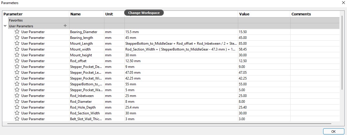
They wanted to place the stepper motor horizontally to the y axis and had to measure exacly where the middle gear was so the Y-axis piece corresponded to the location, that is why their is a pocket at the top of the design. They also needed holes for the bearings to fit through along with the metal rods that the y-axis piece is connected to will go. For the bottom belt connectors, Aaron copied Alarics Y-Axis mount design to make everything consistent.
Aaron worked on the X-axis pully mount design. This design was fairly simple. He kept the same design for the stepper mount and deleted the
Y-Axis Mount
Alaric worked on the y-axis mount with the laser on it. The hole in the middle mounts the laser on it with the 2 slots for connecting the belt on either side on the top. They were originally on the bottom, but we realized that if it were then the laser would be shining on the other side of the belt that isn’t connected into the slots instead of the map. Finally, the 2 holes mount it to the steel rods via linear bearings, and all the edges have a fillet to them.
Corner Connectors
Alaric worked on the corner connectors for the frame. They were fairly simple with just some rectangles and holes for the rods and a fillet. Then later Jada uses this model to add the mount for the actual motor.
Corner Stepper Connector
Jada used Alaric’s original design but had to add a place for the actual stepper motor. She used fusion360. She had the make the mount thick enough to hold the stepper motor because the motor is decently heavy. She first selected the face she was planning to hold the motor off of. Then she created a square then extruded it. She firstly accidentally extruded it ass a joint peice instead of a nerw body but that was an easy fix. She then used the shell tool to create the motor hole. Unfortunately that was off because she had a set thickness in mind but the shell feature messed this up slightly. So she redrew the design then used the offset tool instead which worked amazing. She made the offset 7.5cm because originally it was 3.5cm which was way too thin. Then she added a hole on top for the wires to feed through. After that was added and configured it was ready to print.
EMBED PHOTO
Longitude and Latitude Working With Steppers
Alaric worked on the code for this part and compiled the stepper motor code that had previously been done to get it working into a class that kept track of step phase and with a method to turn everything to low to eliminate a problem we were having with the stepper motor vibrating when not moving. He connected this and the other aspects of the code including getting data from the api and converting latitude longitude to x y coordinates together into the main function, and all this can be downloaded as a zip file with a link at the top of the page.
After the code was finished Alaric and Aaron connected the drivers to the motors and the Raspberry Pi along with the 5V and 9V power supply’s. They ran the code and they initially wanted to test one axis. After typing the plane ID into the terminal on the Raspberry Pi, the motor moved accordingly.
They weren’t able to get the second motor to rotate though. They initally thought it was the power source not providing enough power to the drivers but this didn’t make sense because the power was in parallel. They hypothesized that it could also be the driver that the motor was connected to wasn’t working correctly and after later testing they found out it was the driver. They plugged in everything ran the code a second time and both motors moved accordingly.
Their was one problem that they noted, it was that one of the motors wasn’t rotating smoothly. In the video the motor with the metal gear rotates nicely but the one with blue tape didn’t rotate properly. Either way the code worked, and the problems disappeared in the final assembly.
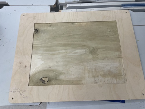
Designing The Wood Base
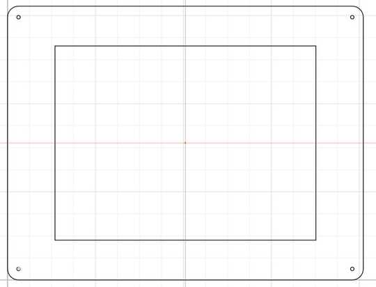
Alaric designed this parametrically in cuttle, and the result can be found in the svgs in the files zip that can be downloaded at the top of the page. It was fairly simple with 4 holes in each of the four corners to have the vertical steel rods go into and a rectangle that would be pocketed out for the map to go into. The corners were rounded, and an offset between the outer edge and the edge of the map was made in accordance with other parts of the design. The pocket cut for the map was made slightly bigger than the map for 2 reasons. Firstly, we wanted the map to be able to be easily slid in. Secondly, we wanted to account for the round bit not cutting all the way into the corner and causing the map not to fit, but we thought using dogbones would not be aesthetically pleasing, so making the pocket bigger would solve the problem while keeping aesthetic elements.
CNC Machine
Then Jada and Aaron started the CNC cut. They loaded the wood onto the board and Jada screwed the wood in the four corners. First they had to do was change the bit to a .5in Bit. Their instructor David Taylor showed them how here:
They then inserted the 0.5in Bit and went to start an aircut. The first time they started the aircut for the inside pocket there was an error. Then Jada noticed there was an error on the XY Datum Position of the Aspire file. It was on the wrong point. After she that was fixed the air cut ran smoothly. Jada and Aaron then started the first cut. Then Jada did rest of the cuts. First she had to change the bit back to a 0.25in Bit. She struggled a bit because it was on pretty tight but she got it eventually. She always air cut first then cut onto the board. First she forgot to reset the Z axis with the new bit so the aircut looked right but the actual cut did not touch the board. She realized her mistake and used the Z axis locater to fix the problem and ran the rest of the cuts well after that. After the cuts were done she took the board off the bed then started using the eletric sander to make it smooth. She used the rouch grit first to fix all the blemishes then the finer grit to make the wood as smooth as glass. It turned out beautifully. She then drilled the four holes first with a 1/4in bit so the wood would not split then a 5/16thin bit. The wood was very soft and easy to drill. She believed it is because the wood is old/dead due to the greenish color of the inside of the wood and the softness of it. Then she sanded down around the drill holes and was done with this.
Designing KiCad PCB For Common Power and Ground
Jada and Aaron started the design for the common grounds and powers on KiCad. They created a board for the Grounds, 12v’s and 5v powers. Jada created one for the grounds but Aaron thought they should add pins for the powers. So they used Aarons final design here:
IMAGE
Milling
Then Jada milled the board. She used a 1/64in Bit for the traces and a 1/32 for the outter cut of the board. She made the Trace Depth 0.20 and the trace clearence 1.50. On one board she accidentally forgot to change the depth and clearence but she realized and made the correct settings. It milled in about 5 minutes and went smoothly. It turned out like this:
IMAGE
Then she sanded the dust parts off and took the nitto tape of the back and was finished with the board. Then
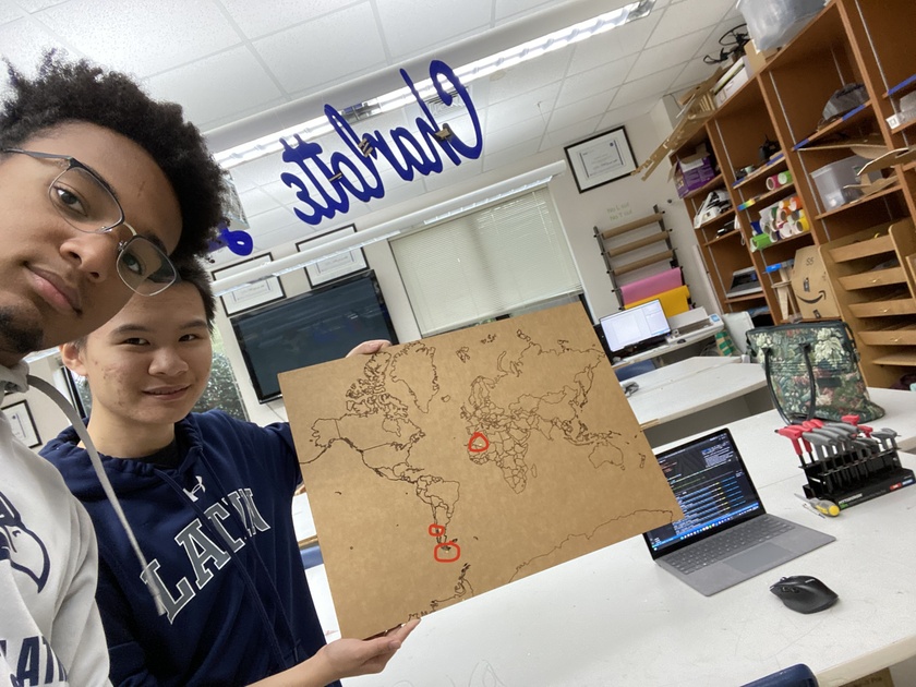
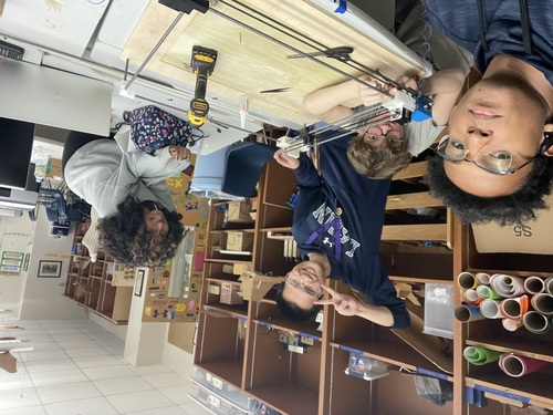
Getting Metal Rods
The group had initally ordered metal rods and bearings but realized that their wouldn’t be enough rod for the whole design so they had to make a trip to Home Depot. Using some calipers they found the rods and caputred this beautiful picture of themselves
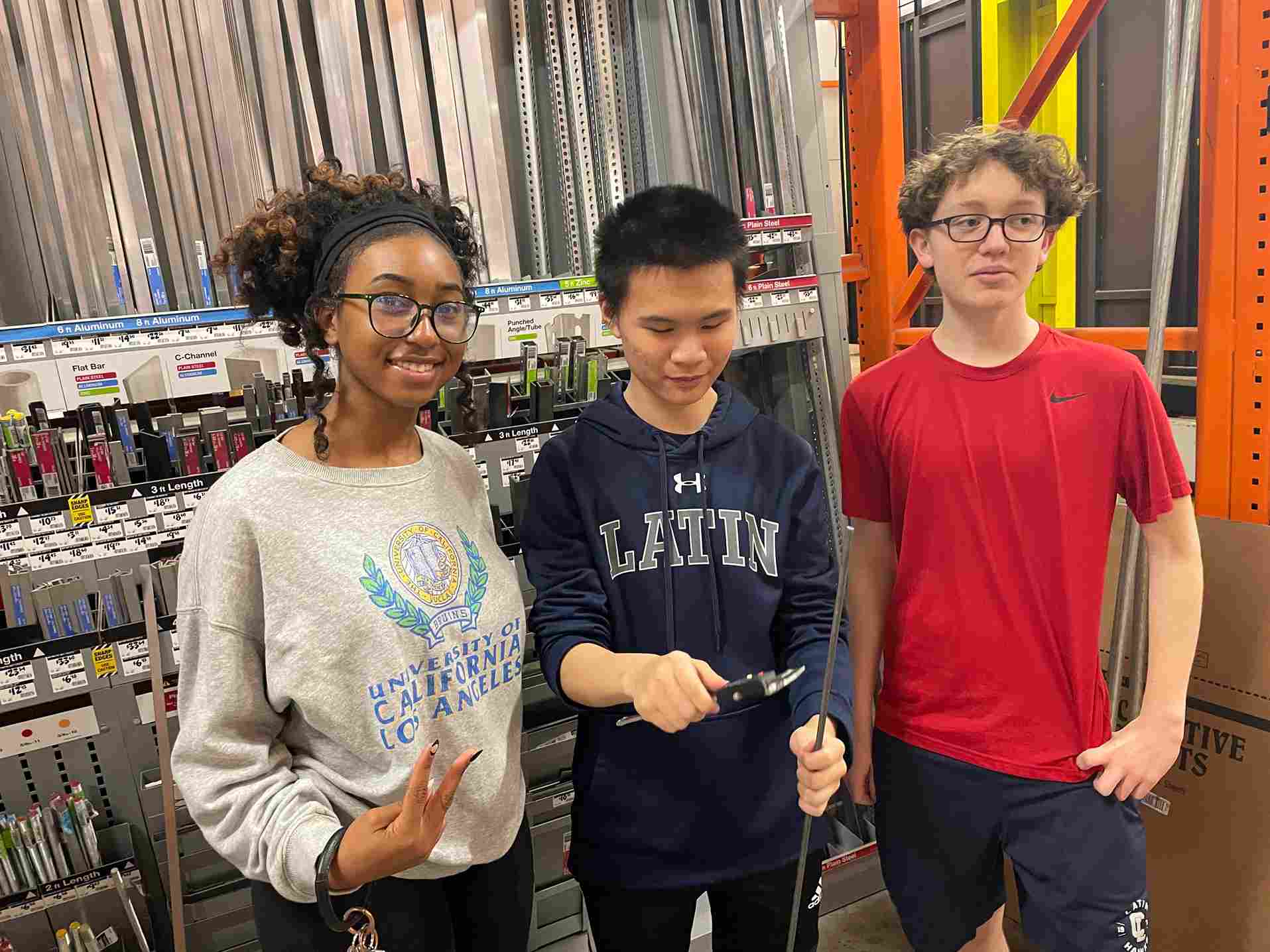
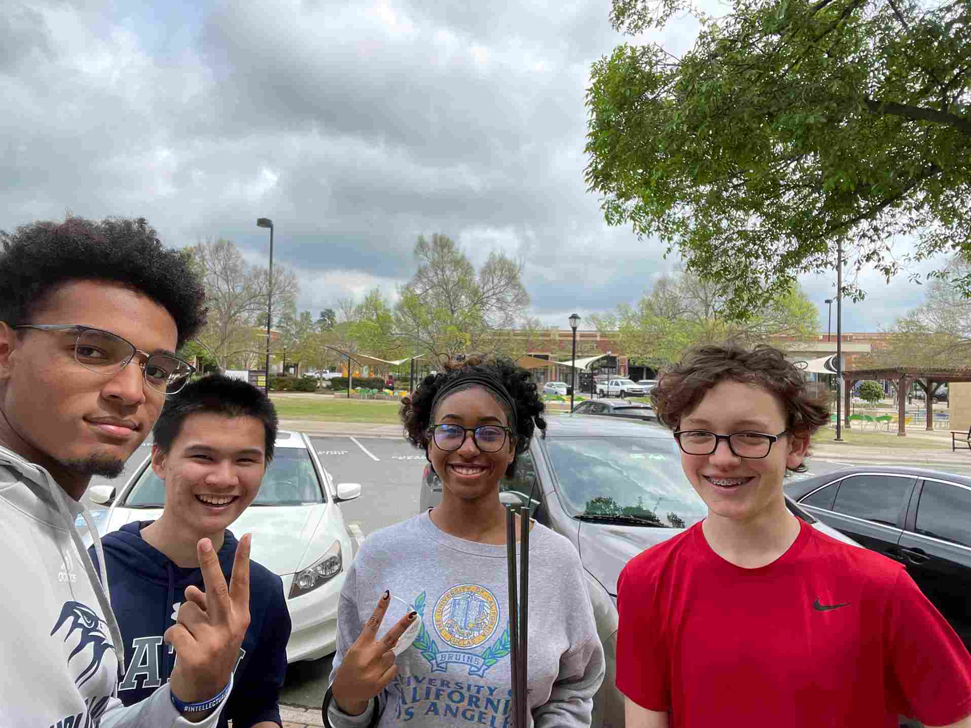
Although they later realized they would need two more so Aaron went and bought two more rods.
Soldering The Laser
Alaric worked on this, it was a simple process of stripping the wires that came with the laser while also stripping some female to female wires and soldering them together. He had calculated that the laser would need a 4.99k ohm resistor but after later testing they realized that the laser wasn’t bright enough so he used a 1k ohm resistor.
Building the Machine
Before the group began construction, the steel rods needed to be cut. Jack and Alaric measured the dimentions needed while everyone in the group contributed in cutting them. Mr. Dubick showed them how to operate the machine using oil while also maintain a frim grip on the rod. The key was to not force it through. Because the group was using steel rods it would take a while before the machine could cut through the rod. Aluminum rods wouldn’ve worked better and is noted for further improvements.
This is the video of Jack cutting the rods
After the rods were cut, the group had to measure the connection between the vertical rods and the wood base. The rods didn’t fit well, so Jada had to file out the wholes using a drill. Afterwards the rods fit perfectly. The group also tested how easy the rods fit into the 3D designed pieces and realized that they had to file out bigger holes. Jack was responsible for this and it worked out well. The rods fit well into the bearings so the group moved on to construction.
Aaron worked on configuring the stepper motors with the new code that Alaric worked on so it would be easy to move the motors with the wires connected to them. At the same time Jack and Alaric worked on connecting the 3D corner pieces to the rods while Jada worked on creating the slideshow. Aaron eventally finished the stepper motor configuration and began assiting Alaric and Jack with the machine.
The problems that they faced were connecting pieces too early. At First they connected the corners and connected them to the bed. Then they realized that they forgot the middle axis pieces and had to connect them. Aligning the X-axis and Y-axis was more difficult than expected but they eventally got it to work. They had to use a mallet so the pieces stuck together. Their was another problem though, the rods were a little bent and their was a dip, so the bearings could only move a certain distance without recieving any resistance. They realized that the pieces weren’t fully connected, after malleting them together it fix the problem a conciderable bit but not fully. The bearing couldn’t slide only at the edge of the machine so it didn’t impact the movement along the map. The next step was to connect the stepper motors with its corresponding 3D piece. the Y-axis stepper motor fit in perfectly, but the X-axis piece required some filing before the motor could fit in and Jack worked on this. The next step was to connect the belts to gantry. Alaric and Jack worked on this but ran into some problems when they cut too much string for the X-axis, but luckily it was enough for the Y-axis. The 3D rods on the opposite side of the motor for both axis were too large so Aaron had to cut those down. After all of this, they connected the belts and the gantry was complete.
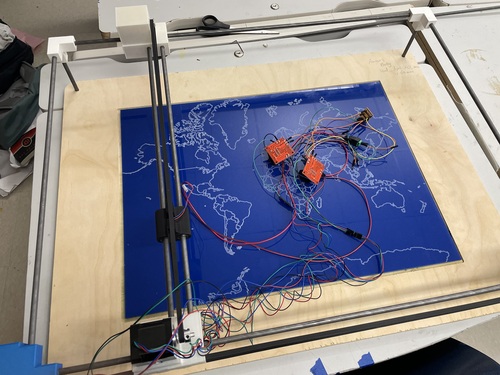
Since the code was already finished and the motors configured all that was left was to power up the Rasbperry Pi and connected the drivers to the Pi. The board that Jada had created was extremely helpful in simplifying where all of the wires were connected to. They had to connect the power supply to the driver and the laser. The shared groud concisted of both drivers, the Raspberry Pi, the laser and the external power supply for the drivers.
Once everything was plugged in, they ran the code but ran into some problems, the motors weren’t working properly. The Y-axis began moving backwards even though both axis were at the origin. It almost broke the machine if they didn’t disconnect the power. This was due to the wrong wires being connected to the stepper motors. The wires designed for the Y-axis were connected to the X-axis and vice versa. After making this change, they ran the code but the motors still didn’t move. Aaron noted that something was smelling weird and quickly diagnosed that it was drivers. They were connecting a 12V power supply to the drivers but that was way too much voltage and switched it out for a 5V 10A power supply. After making this adjustment, they ran the code again and the machine worked. The inital goal was to track Elon Musk, but with his plane not flying so they choose a plane in the middle of the Atlantic and the laser went to that location.
Possible Improvements
The group was happy that they finished, even if it was the day before it was due. However, they were much more areas to imporve the machine.
- Using aluminum rods so there isn’t any bending in the gantry
- Impliment a Z-axis so people could track the altitude of the plane
- Create a LED screen on the machine so the planes ID could be shown
- Fileting the 3D designs more
- Get a brighter laser
- Create a compartment so the drivers and Raspberry Pi could sit without the wires being seen
- Design bigger holes for the rods to fit into
- Insert molding the map into the machine bed to eliminate the empty edges of the pocket
- Having a 3D printed plane that rotates on top of the laser mount to track the bearing of the plane