9a. Embedded programming
This week, our group needed to compare the architectures of different chips and devices. We decided to use our lab’s Nvidia Jetsons as well as Raspberry Pis, since we had already been working without ATTiny chips and Arduinos for a long time.
Group A1
Raspberry Pi
Nick worked with the Raspberry Pi for group A1. The goal was to use Raspbian to test different codes and look at the specs of the device and later compare those specs to the other architectures we were going to use.
Rasbian is a linux-derived OS for the Raspberry Pi
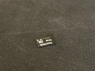
Nick first took an old SD card preloaded with Raspbian and grabbed the Pi itself. After some plugging in of a monitor and peripherals he went to boot up the Pi itself to make sure it would work.
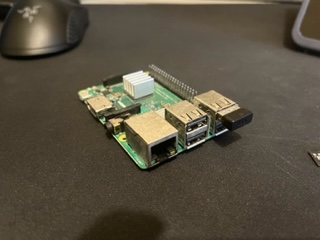
After doing so he plugged it in and the boot screen for the Pi was displayed onto the monitor:
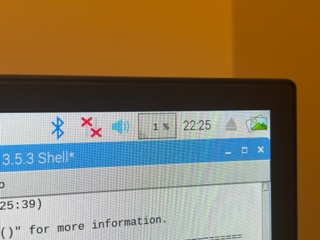
Once in, after going through tons of random old files on the Pi for fun, he looked through to try and find some sort of stress test or information about the computer itself. In the top right of the GUI, a small box with a percentage and bar chart under showed the CPU usage for the current time. He opened multiple Chrome tabs and python shell applications to test it, and it held up rather well only reaching around 34% usage with tons of programs opened.
This image below shows the box in general but not when under stressed as talked about above
He went digging on the specs of the Pi next. This Pi in particular was a Pi 3 B+ from around 3 or 4 years back. According to the Official Raspberry Pi 3 B+ Documentation, these were the specs:
| Part | Specifications |
|---|---|
| CPU | Cortex-A53 64-bit SoC @ 1.4GHz |
| Memory | 1GB |
| Power Required | 5V/2.5A DC |
Benefits of the Pi
The Pi as opposed to a normal chip like the ATTiny or Arduino boards has the ability to carry an entire operating system as well as having onboard wifi in addition to still having pinouts just like arduino but with the language in Python. Let’s compare the stats to an Arduino this information found in the arduino docuemntation:
| Part | Specifications |
|---|---|
| CPU | ATmega328P |
| Memory | 2KB SRAM, 32KB FLASH, 1KB EEPROM |
| Power Required | 7V-12V |
In comparison of power, the Pi far outweighs the Ardunio Uno in all aspects. With its furthered capabilities such as the onboard wifi and ability to run an OS and basically be an entire desktop computer, the Pi’s abilities are much greater than that of the Arduino. Lastly the cost comparison, the Pi costs $35.00 while an Arduino costs as little as $22.00 at the time of writing this though both used to be a lot cheaper. Overall as well many projects don’t nearly require the power of a Pi, not to mention everything else you need to buy for the Pi whereas an Arduino and some parts is all you need. Overall, both have very specific use cases for what you are trying to do but the Pi is much more powerful than an Arduino.
Blinking a light on the Pi
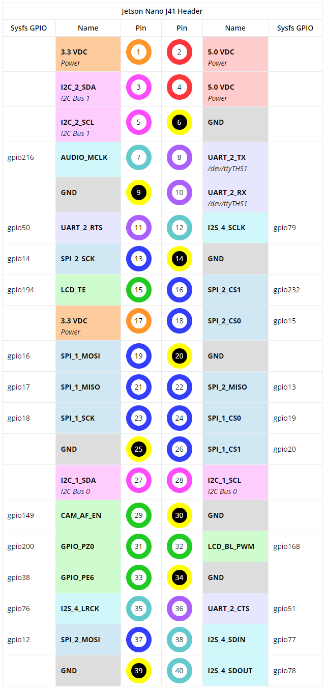
Next, Nick’s goal was to blink an LED on the Pi using the Pi’s pinouts and python. 2021’s group site for our lab helped tremendously in the syntax and pinouts of the Pi, linked here. From reading their documentation, Nick learned that the pinouts were super easy to find online and also that the Python syntax was rather simple. He began writing his own code, and used a GPIO output chart from here seen below as reference to write the code and to get a better understanding of it instead of just stealing the previous year’s code. I decided to use GPIO pin
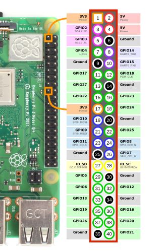
From this Nick selected GPIO 7.
from gpiozero import LED;
from time import sleep;

ledOutput = LED(7); #GPIO 4

while True:
    ledOutput.on();
    sleep(1);
    ledOutput.off();
    sleep(1);
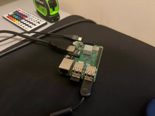
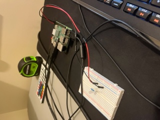
Then he built the circuit with a breadboard:
And then ran the code, however, it didn’t work. After some trouble shooting, Nick realized the chart above was misleading and that the pin number in the code had to be set to the number after the GPIO instead of the actual numbers in the middle of the chart over the pins. He fixed it:
from gpiozero import LED;
from time import sleep;

ledOutput = LED(4); #GPIO 4, PIN 7!

while True:
    ledOutput.on();
    sleep(1);
    ledOutput.off();
    sleep(1);
And the light blinked perfectly.
SAMD11C
Testing
For this week, Andrew worked on testing the architecture of the SAMD11C microchips that all of our lab’s students used in their programmers. More information about the programmers can be found on our instructor Dr. Harris’s site, or in our week 5: electronics production documentation. Since Andrew had previously lost his programmer, he had to make another one, and so it was the perfect opportunity for him to test the SAMD11C’s architecture.
After remilling and soldering the components on once again, Andrew’s programmer looked like this
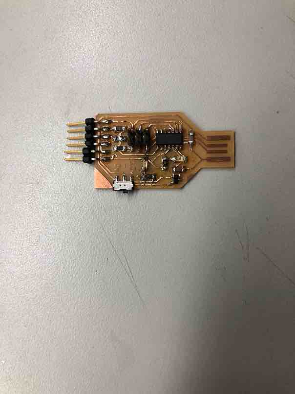
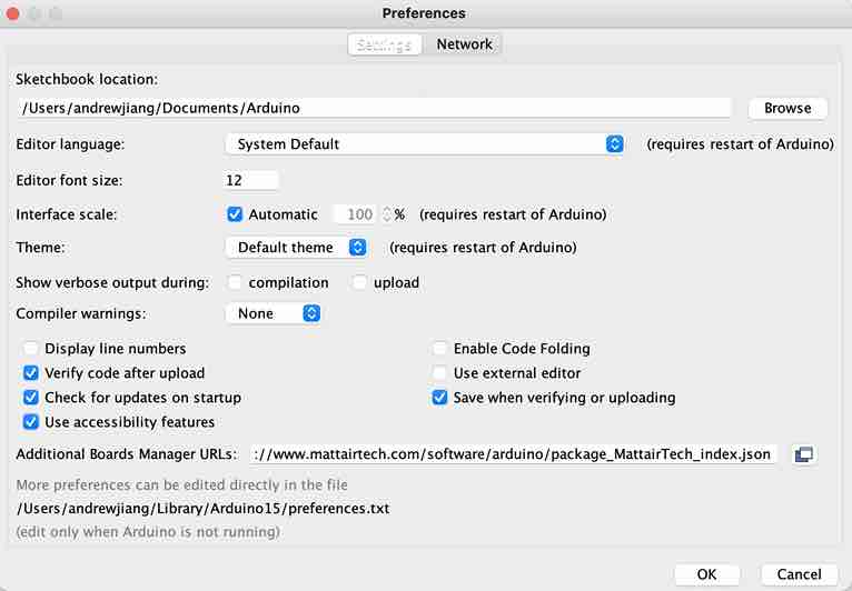
He then plugged it into his computer to verify that it got power, and the middle red led lit up, indicating that it did accept power. After turning it into a programmer once again with an ICE board, Andrew then pulled up Dr. Harris’s site once again and went through some of the steps for testing code. First he had to download the mattairtech additional boards url so he could configure the settings for the SAMD chip in Arduino. He went to the Arduino software, and went to File->Preferences and copied this link into the Additional Boards Manager box.
https://www.mattairtech.com/software/arduino/package_MattairTech_index.json
This was the result
First, he wanted to test that basic serial communication could be established between the board and the computer, so he wrote some basic print code as shown below
void setup() {
  Serial.begin(9600);
}

void loop() {
  Serial.print("hello");
}
This was the result
After testing that it could establish serial communication, which it could, I tested its capabilities by blinking the internal LED. This is the code I wrote, and its really just the modified blink code. I checked the pinout of the SAMD and the LED was connected to pin 2.
int led = 2;
// the setup routine runs once when you press reset: void setup() { // initialize the digital pin as an output. pinMode(led, OUTPUT);
}
void loop() { digitalWrite(led, HIGH); // turn the LED on (HIGH is the voltage level) delay(1000); // wait for a second digitalWrite(led, LOW); // turn the LED off by making the voltage LOW delay(1000); // wait for a second }
This is what happened when it worked.
To make sure that it controlled the LED, I made it blink faster, changing the delay to 500 ms instead of 1000 ms. I found success.
Conclusion
With each test of the SAMD11C, the uploading time was a lot slower compared to other chips since the software always had to go through the extra steps of writing bytes to flash. However, the SAMD11C is one of the most versatile microchips, and you either turn it into a programmer for other microcontrollers, or just program the SAM chip directly. Thus I think that the SAM architecture is a strong contender within all the different kinds of microcontrollers because it is a lot more flexible than say, an ATtiny412.
NVIDIA Jetson
Group A2
This group consists of Alaric, Aaron, Jada, Pari
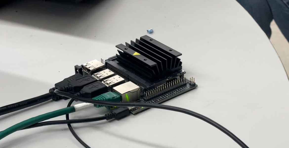
NVIDIA Jetson NANO
<<<<<<< HEAD Aaron, Alaric, and Pari worked on setting up the jetson nano. It functions similarly to a raspberry pi so it requires a monitor, mouse, and a keyboard although it was designed to utilize AI. They booted up the device with a goal of lighting an LED. They used this site as a workflow. When activating it they recieved a sign in screen but the user was dated back to the year 2019. They couldn’t figure out the password and were locked out.
Pari tried to figure out the user, by reaching out and finding the most used passcodes in the lab. Although, there wasnt any luck so, she proceeded to as Alaric, to help find a solution.
Aaron, Alaric, Jada and Pari worked on setting up the jetson nano. It functions similarly to a raspberry pi so it requires a monitor, mouse, and a keyboard although it was designed to utilize AI. They booted up the device with a goal of lighting an LED. They used this site as a workflow. When activating it they recieved a sign in screen but the user was dated back to the year 2019. They couldn’t figure out the password and were locked out.
675691fb0de4aba809472ba77619b1af86eae25b
Alaric and Pari proceeded to first wipe the sd card with some advice from Jack by using rufus.
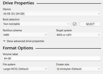
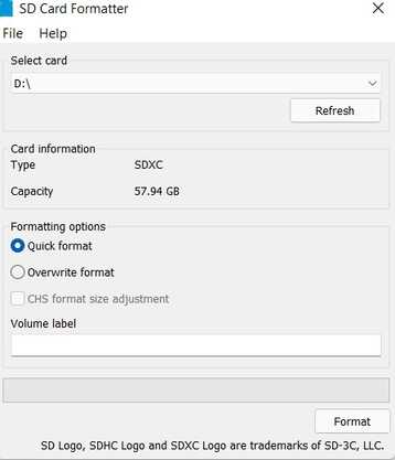
<<<<<<< HEAD Pari and Alaric then followed the instructions on the jetson nano site. After downloading the sd card image from it, Alaric downloaded and launched the sd card formatter for windows to format the sd card. ======= They then followed the instructions on the jetson nano site. After downloading the sd card image from it, he downloaded and launched the sd card formatter for windows to format the sd card.
675691fb0de4aba809472ba77619b1af86eae25b
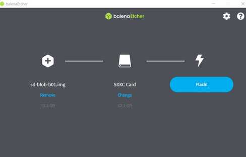
To finish setting it up, he used balena etcher to flash the previously downloaded sd card image onto the sd card.
Aaron and Jada after the card was reset proceeded to create a new account for the Jetson. He had to connect an ethernet to the Jetson because the commands for the workflow required python and the code was also python based.
They went to the python website to download version 3.8.6. After downloading it he ran into some errors about pip and pip3 not being recognized as commands. After a lot of reaserch Adam Durrett helped him find this line of code apt-get install python-setuptools. After writing this, pip was installed and he was able to pull the Jetson GPIO library from the internet. The repository is also available here. After typing this he followed the rest of the workflow.
They created a new directory then typed this command which allowed him to type code into
gedit gpiodemo.py
They used the code below
# GPIO library
import Jetson.GPIO as GPIO

# Handles time
import time

# Pin Definition
led_pin = 7

# Set up the GPIO channel
GPIO.setmode(GPIO.BOARD)
GPIO.setup(led_pin, GPIO.OUT, initial=GPIO.HIGH)

print("Press CTRL+C when you want the LED to stop blinking")

# Blink the LED
while True:
  time.sleep(2)
  GPIO.output(led_pin, GPIO.HIGH)
  print("LED is ON")
  time.sleep(2)
  GPIO.output(led_pin, GPIO.LOW)
  print("LED is OFF")
They looked at the pinout of for the GPIO’s and connected the wires accordingly.