6b. (CLS Adults) 3D Scanning and printing
Ender 3D Pro Printer (individual)
First Time Use- Leveling the Print Bed
- Press round black knob/dial to select “Prepare”–> ”Auto Home” and wait for printer nozzle to stop moving near the front left of the bed.
- Press round black knob/dial to select “Prepare”–> ”Disable Stepper”. Physically move the nozzle end to the front left corner.
- Obtain a piece of standard computer paper.
- Place the computer paper between the print bed and the nozzle.
- Twist the large black leveling screw (clockwise = up; counterclockwise = down) until there is gentle resistance between the nozzle and the build plate.
- Move the nozzle to the back left of the build plate and repeat steps 4-5.
- Repeat these steps with all four corners of the build plate.
- Repeat steps 1-8 when necessary (when printers is physically moved, or a disturbance has occurred).
Everyday Use
- Clean glass bed with a paper towel saturated with alcohol.
- Turn on Ender 3 Pro (switch on the side).
- Insert SD card into front (lower left) of machine.
- Press in the round knob on Ender Pro control panel to see menu screen.
- Select “Prepare”–> “Auto Home”. Wait until printer is finished (stops).
- Select “Print from TF”.
- Turn black dial (scroll) until you see the file you would like to 3D print.
Prusa 3D Printers (Mini and Regular) at CLS Fab Lab
Workflow for Prusa Printers in CLS Fab Lab:
- Design object in CAD software (like TinerCAD, Google Sketchup, Fusion 360, etc).
- From the CAD software, download (or “Export”) the file as a .STL file.
- Decide which Prusa printer will be used (regular-sized or mini). Printer selection should be based on the size of the object that is being 3D printed. Larger jobs should ideally be 3D- printed on the Prusa Regular; smaller jobs should be printed on Prusa mini’s.
- Open the file in a “slicing” software (like Prusa, Cura, etc). The software at the Charlotte Latin School Fab Lab is Prusa Slicer 2.3.3.
- Select File–>Import–>your file name. Once open, the object to be 3D-printed should be on the virtual bed.
- Orient the object on the virtual bed in the slicing software into an optimal position (such that overhanging parts have contact to virtual print plane as much as possible).
- Decide which print settings will be used. Note: The object’s size can be scaled in Prusa slicer if needed. Be sure to lock/unlock the “Lock” icon appropriately. This icon is located to the left of “Scale factors” and “Size”. (See below.)

- In the slicing software, “slice” the object and obtain the g-code (a file that contains information about the print job and is interpreted by the 3-D printer) by clicking on “Export G Code in the lower right-hand side of the screen.
- Save this file where it is easily attainable on the computer, but rename it to include your last name and the length of time to print.
- Open the document that contains the URL links for all of the Prusa printers in the Charlotte Latin School Fab Lab.
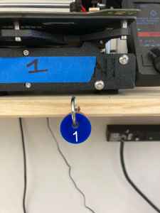
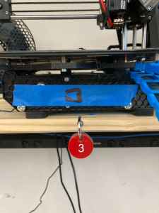
- Check which printer is available (not being used). This is determined by checking the color of the acrylic tag hanging by the hook in front of the printer. Red= In Use; Blue =Available
| Printer Available | Printer Not Available |
|---|---|
 |
 |
- Using a paper towel saturated with rubbing alcohol, clean the bed of the 3D printer you intend to use.
- Turn the acrylic tag to show the red side.
- Return to the computer that houses the file you are printing.
- Click on the link for the printer that you intend to use; upload the G-Code for that file. Double-check that you have selected the correct file.
- Make sure the printer is connected. Click on “Connect” if not. (See image below).

- Select the “Printer” icon to the bottom right of the file you are trying to print. (See below).
- Return to the 3D printer and watch the first layer go down. If the job looks flawed, cancel the job on the raspberry pi connected to the 3D printer.
- Once 3D print job is complete, remove it from the bed. This can be done by: 1) removing the magnetic cover, and slightly bending it; or 2) using the metal scraper to scrape it off. (If this method is used, be sure to wear a protective glove on your non-dominant hand.

Form 3S Printer at CLS Fab Lab
Setting Up Job in Resin Printer
- Open FormLabs PreForm 3.23.0 on computer in Charlotte Latin School Fab Lab.
- Open model file (either .STL or .OBJ).
- Select type of resin (on right-hand side) that will be used (either Tough 2000 or Durable) on the Form 3B printer.
- Go to File–> Open. Bring file in. It will place the file in the virtual workplane.
- Choose Printer Type (Form 3B for CLS).
- Choose a durable resin v2.
- Choose layer thickness (default is o.1 mm; or 0.05 mm).
- Choose print settings. Use defaults.
- Type in a job name.
- Hit “Apply”.
- On right side of screen, verify “Printability”. This should be green in color.
- On left side of screen, click on orange “Start A Print” button.
- Select a printer; this should be selected based on material type.
- Choose “select”.
- Then “Upload Job”.
- Go to printer and follow on-screen prompts.
- Confirm that the build plate is locked.
After Job Is Complete
- Pull entire build plate out.
- Open the washer and slide entire build plate onto the ledge.
- Start washer for a twenty-minute cycle (for the Durable resin).
- When wash is finished, put on disposable gloves.
- Carefully pry the print job from the build plate.
- Place print job (alone) in curing machine for sixty minutes.
- Remove print job from curing machine.
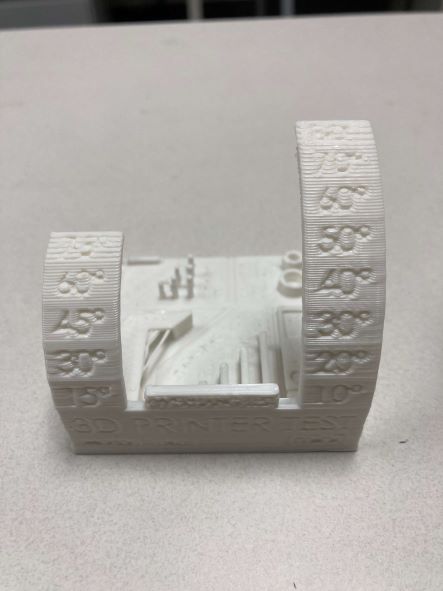
Printer Comparison
| Individual Pictures |
|---|
 |
 |
 |
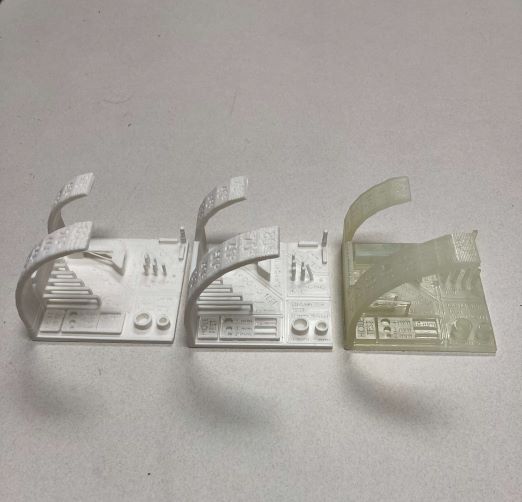
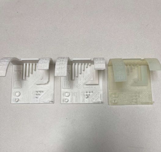
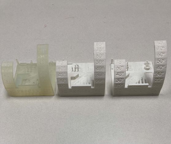
| Comparison Pictures |
|---|
 |
 |
 |
| Variable Tested | Ender 3 Pro 0.4 Nozzle | Ender 3 Pro 0.8 Nozzle | Prusa Resin Printer |
|---|---|---|---|
| Overhang/Angle Test | Good until 60 degrees | Good until 50 degrees | Good until 60 degrees |
| Bridging | Flawless | Nearly flawless; comes up short near junction with post | some delamination starting at 10mm bridge test |
| Wall Test (Diameter) | Measures at 1.02 mm | Measures at 1.35mm | Measures at 1.18mm |
| Dimensions (Scale Test-relative to 10mm on X axis) | 10.1mm | 10.17mm | 10.0mm |
| Dimensions (Scale Test-relative to 10mm on Y axis) | 10.23mm | 10.25mm | 10.05mm |
| Dimensions (Scale Test-relative to 10mm on Z axis) | 10.08mm | 10.15mm | 10.07mm |
| Anisotropic Observations | equivalent for all | equivalent for all | equivalent for all |
| Surface Finish Observations (Letters in the X/Y) | Acceptable; a little “ironed over” | Illegible; over-taxed nozzle | Pristine |
Infill
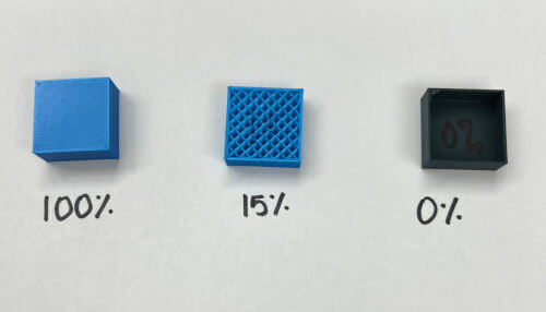
We printed a cube with three levels of infill (0%, 15% and 100%). We paused the prints mid-way through in order to see the infill (without the “lid”). We chose rectilinear infill (no other types were recommended at 100%). The image above shows all three cubes. The 0% infill setting would be used when a shell is needed. Fifteen percent is a good starting point for normal solid features; 100% is normally unnecessary and wasteful. However, this could be useful when compression strength is needed.
Last update: May 24, 2022