Week 10. Output Devices (Mar 22)
Week 10 Assignment
- add an output device to a microcontroller board you’ve designed, and program it to do something
ESC Tester
This week, the idea for an output device I had was an ESC Tester, or a board that could control a brushless dc motor. This is somewhat similar to Neil’s board using an ATTiny44 chip, but I modified it to use an ATTiny412 chip since that’s what I’m most familiar with, and the ATTiny44 uses old architectures. A main reason I decided to make an ESC Tester, is because being able to control the brushless motors is a big part of my quadcopter project.
At the beginning of the week, I had some idea that I was going to do something pertaining to brushless motors, but not really a concrete idea of what I was going to do. By the week’s end, I understood a lot more about controlling brushless motors, electronic speed controllers, and my final project.
Using Arduino
Starting out I decided to try to control the motor using an arduino before I immediately jumped to making a board. I’ve noticed this pattern when learning electronics that one should often test something first on an arduino. Because if something is not working with an arduino, we can most likely assume its not a problem with the board or soldering and just focus on problems with how we’re using it. This allows me to narrow down the problem in my thinking and learn much more about just the specific thing such as brushless motors or whatever it is I’m trying to do.
First doing some research, I found this tutorial and wired up the arduino to the ESC and BLDC like the tutorial showed. I didn’t include the joystick since I wasn’t looking to control it with a joystick yet, just to get the BLDC to spin. Then I learned from my instructor Dr. Harris that I have to calibrate the ESC before spinning the motor, which I followed the instructions on William Zhou’s Fab site to do.
These were the steps I followed
-
Without the ESC powered, send max throttle to the ESC by writing a ms of 2 to the ESC. This will make it enter programming mode.
-
Power up your ESCs. A series of three beeps will occur to say that the power supply is okay.
-
Now send the min throttle to the ESC by writing a ms of 1 to the ESC.
-
Your ESC should now be calibrated!
It is important to note that on steps 1 and 3, instead of writing a 2 and 1 to the serial monitor, I wrote a 2000 and 1000 respectively instead. This is because I had it in microseconds instead of milliseconds on accident.
I followed this code from his site. From this, I did learn that servos and brushless motors are very similar since he used the servo library to control the BLDC.
#include <Servo.h>
Servo ESC;
int pwm = 1000;

void setup() {
    Serial.begin(9600);
    ESC.attach(4);
}

void loop() {
    if (Serial.available()) {
        pwm = Serial.parseInt();
    }
    ESC.writeMicroseconds(pwm);
    Serial.print("uS = ");
    Serial.println(pwm);
}
This was the setup
It didn’t work the first time because I had the arduino setup incorrectly. I fixed it soon after and it finally worked to spin with my commands in the serial monitor.
Iteration 1
Before doing anything with the designn, I decided to some research on other people’s boards. I started off by looking at Neil’s board for brushless motors and studying what he had on it, and then extrapolating that information to use on the Attiny412 board.
I noticed a few odd components I had never seen before on Neil’s board, including a 20 MHz crystal oscillator and ISP 6 pin header. At the time, I didn’t really understand how ISP worked, but I correctly assumed that I didn’t need it since I was programming through UPDI interface instead.
Next was the 20 MHz crystal oscillator, which I wasn’t sure about what it did. I searched up crystal oscillators, and found that they were for providing a stable external clock source, which was normally internal to the chip. I thus reasoned that 20 MHz must be a necessary clock frequency in order to control ESCs, and that the reason he had added the external oscillator was because it wasn’t internal to the ATTiny44. After looking at the Attiny44 datasheet, I found that there was no 20 MHz option, and so the external oscillator made sense.
Atmel ATtiny24/44/84: 0 - 8MHz at 2.7 - 5.5V, 0 - 16MHz at 4.5 - 5.5V
However, since I was planning on using an ATtiny412 chip instead I looked at that datasheet to see if I needed to use an external oscillator. I determined that the ATTiny already had a capable internal oscillator at 20 MHz so I didn’t need an external crystal.
16/20MHz Low Power Internal RC Oscillator
This conclusion was confirmed when I read this sentence in Sophia Vona’s output week documentation.
I could completely remove the external clock aspect, since the clock inside the Attiny412 could already operate at 20mhz the external clock was unecesary.
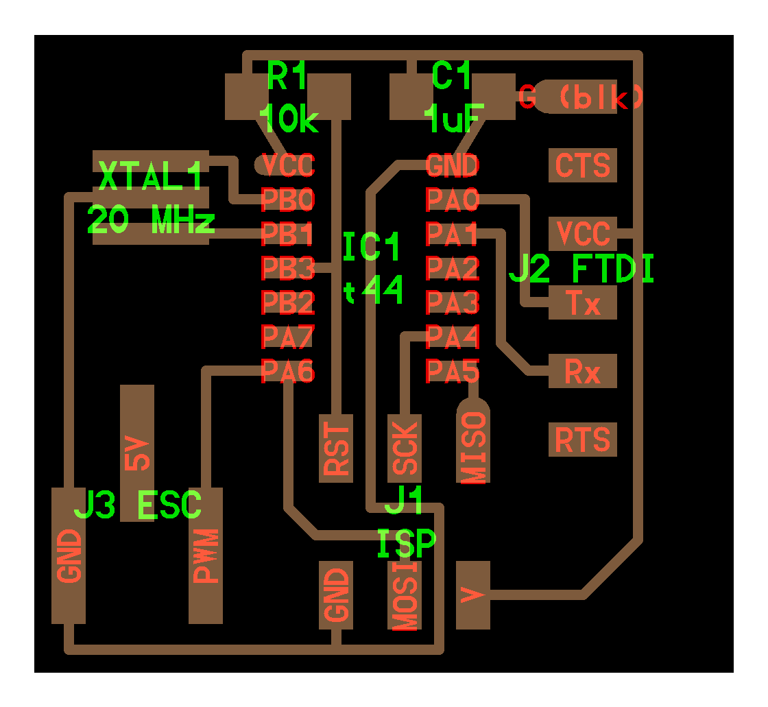
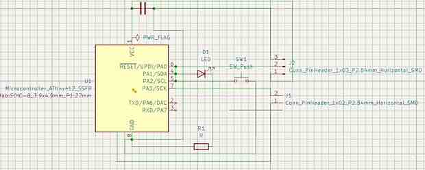
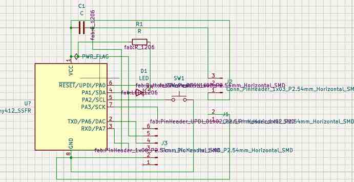
Thus I found that I didn’t actually need an external clock in the design.After determining this information I began to work on the design for my board in KiCAD. Here is the schematic of my first iteration board, which is basically just the board I made for Week 07 Electronics Design with two extra header pins, which go to ground and the data line of the ESC. We don’t want the power pin of the ESC because we are already receiving external power through the battery.
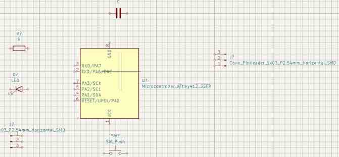
These are my components that I used
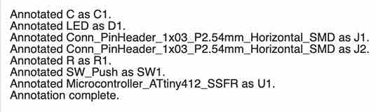
This is the message I received after annotating the components.
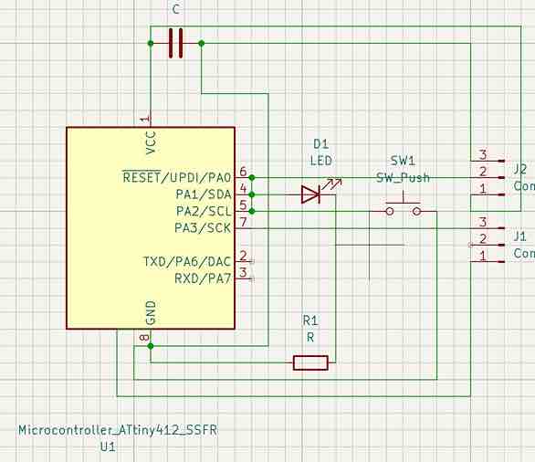
Here is a schematic which has one extra header. The reason for that is because I didn’t realize that I didn’t need the power pin of the ESC at first, and it was only after looking back at William Zhou’s design, that I figured this out. Below is the finished schematic.
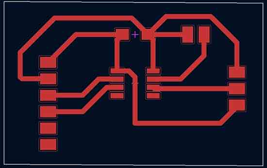
After finishing the schematic I moved into PCB editor, where I drew out the edge cuts and traced the tracks between my components.
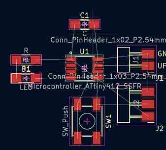
Again here are the components.
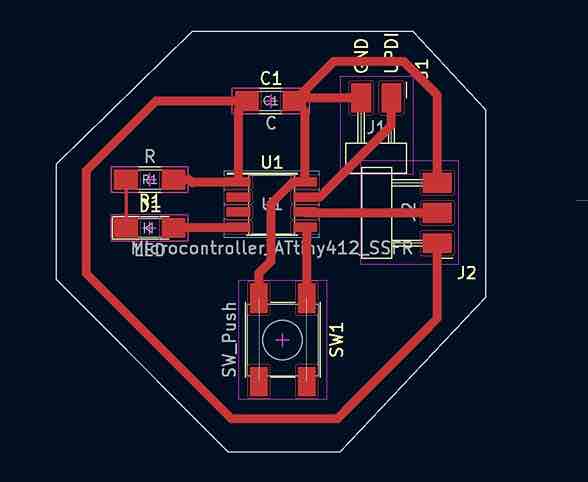
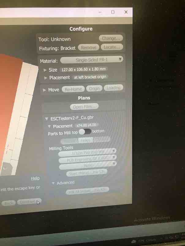
That’s the design for my PCB, which I generated and saved the gerber files for when I was ready to mill a board. Next I worked on milling the first iteration of my board out. First I took my F.Cu and Edge Cuts files, imported them into the Bantam software, and setup the milling settings including placement, tools, and trace width and clearance. Then I changed the bit to a PCB 0.005 Engraving bit
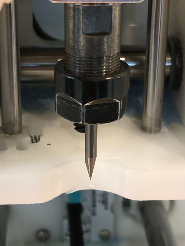
Next I located the tool after by clicking change tool in the software.
Then I probed the thickness of the material. I had to move the tool to get it in the right spot or the thickness wouldn’t be accurate completely
Next I actually probed the thickness using bitbreakers
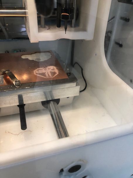
Once I probed the thickness, I hit mill all visible and the traces were then milled out. This was the result.
Next, I swapped the tool out for a 1/32 flat end mill. The machine prompted me to relocate that tool as well, which I did.
Then the machine automatically continued to mill the edge cuts out.
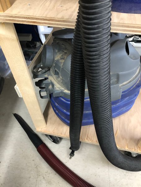
After milling the complete board, I used this vaccuum to clean up.
Then I populated the board with the same components as week 07, only adding two more additional headers for the ESC. As a reminder these components are
-
Attiny412 chip
-
1uF capacitor
-
pushbutton
-
blue LED
-
330 ohm resistor
-
2 pin header for ground and data of the ESC (power is not necessary because it comes from external battery)
-
3 pin header for ground, VCC, UPDI for UPDI programming through arduino
I then used an Arduino with the jtag2updi sketch already uploaded onto it from before to program my board to blink, which confirmed that the UPDI programming worked.
To make sure I was indeed controlling the LED, I made it blink faster.
Next it was time to see if it could actually control the ESC. I tried running the ESC code from the Arduino test but unfortunately, when I plugged in the GND and data wires of the ESC into the two pin header and ran the program, my ATTiny412 chip started smoking immediately. I quickly unplugged the battery powered ESC and tried testing the blink program again, but it wouldn’t run. My chip had burnt up.
After remilling and soldering another board once again, I carefully plugged in the ESC and ran the program, and the ATTiny chip did not smoke. However, I could not establish serial communication and was very confused as to why nothing was showing up in the serial monitor. Asking Dr. Harris for assistance, he advised that I needed a 6 pin FTDI header and an USB to serial converter board in order to actually view the serial outputs of the ATTiny412. Luckily, we had the USB to serial converter, but unluckily, I had to redesign and remill the board once again since I did not include an FTDI 6 pin header in my last one.
Iteration 2
After receiving the news that I needed an FTDI six pin header, I worked on completely reworking my design. At first I thought that I could fit everything, but I simply realized that I didn’t need all of this complexity.
After countless failures, I knew that I wanted things to be simpler. I took a look at my board and removed all the components I didn’t think were necessary, including the LED, pushbutton, and resistor. I had originally placed those there to verify that a board worked by blinking an LED, but now I felt that wasn’t completely necessary since I would know if a board worked if it controlled the ESC, and the LED seemed like just one more thing to get wrong.
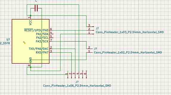
Thus I redrew my schematic for simplicity, only including the 6 pin FTDI header which I wired to VCC, GND, Tx, Rx of the ATtiny, 2 pin header for the ESC going to GND and pin 5, and 3 pin header for UPDI going to pin 6, GND, and VCC.
After redrawing the schematic, I then put it back into the PCB editor once again and went through the same process of tracing the tracks and drawing edges.
Then once again I went through the process of milling. Here you can see the settings I used.
Here is me moving the bitbreakers to the correct location, after locating the PCB 0.005 Engraving bit.
This is when the PCB bit was actually milling out the traces.
Next I used a 1/64 end mill, and here is the result of locating the bit.
Then finally I used a 1/32 end mill tool, and here is the location of that bit.
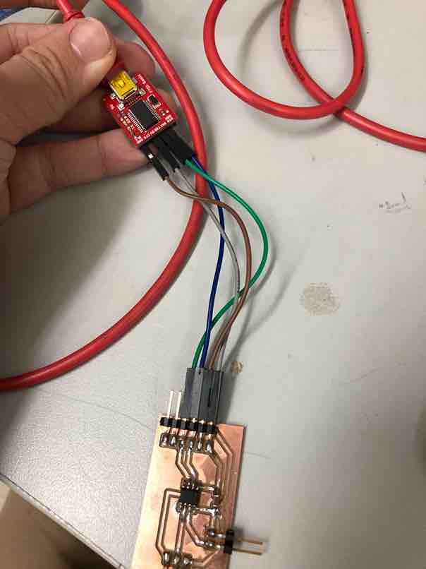
After milling out the board, I then populated it with the components and began working on trying to program. I initially tested the basic serial communication capabilities of the board. First I would upload a program through the UPDI programmer arduino, and then plug in a usb to serial converter board, wiring up Tx, Rx, GND, and 5V. I could have used my programmer board at this point, but I just decided to do an Arduino.
Then after connecting the usb to serial I tried reading the serial monitor, where I eventually found success. This taught me to do serial communication with the microchips whereas before I was simply uploading programs to blink LEDs and such. Here is how it was wired to the converter.
At first, I tested this extremely basic serial code that I wrote.
void setup (){
Serial.begin(9600);
}
void loop(){
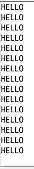
Serial.print("HELLO")
}
That resulted in this gibberish being printed from the serial monitor, but at least I knew that there was serial communication.

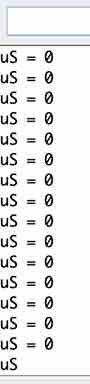
Then I tried adding a small delay(100); between prints in the void loop function, which gave me success.
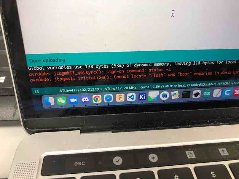
Its important to note that I did get this error all throughout my testing, even with the iteration 1 board. After doing some research on the Arduino documentation of this error, the only solution that I found was this.
Make sure you have selected the right board and port correct board under Tools > Board and Tools > Port.
I rechecked the ports and board and they were all correct, and when I ran the sketch again I kept receiving this error. After some dives into multiple forums with no clear answer, I came across this answer. It read
This is normal and expected and doesn't indicate any problem. Please ignore it.
I decided to trust it since I had found no other clear answer when looking at the forums. Also, it seemed to be simply a warning message and not something that would affect the actual program.
Taking it very slow, I then went back to the ESC code I had before, and added a line to make sure that serial communication was being established with this code. I did not, however, wire up the ESC just yet since I was afraid of my ATTiny smoking like the previous version did. This was the code that gave me success.
#include <Servo.h>
Servo ESC;
int pwm = 1000;

void setup() {
    Serial.begin(9600);
    ESC.attach(4);
}

void loop() {
    Serial.print("downloaded");
    if (Serial.available()) {
        pwm = Serial.parseInt();
    }
    ESC.writeMicroseconds(pwm);
    Serial.print("uS = ");
    Serial.println(pwm);
}
For the next step I took away the downloaded message and tried to see if it would still communicate. Then I tried calibrating the ESC once again using the same steps as before.
-
Without the ESC powered, send max throttle to the ESC by writing a microseconds of 2000 to the ESC. This will make it enter programming mode.
-
Power up your ESCs. A series of three beeps will occur to say that the power supply is okay.
-
Now send the min throttle to the ESC by writing a microseconds of 1000 to the ESC.
-
Your ESC should now be calibrated!
I didn’t want to take any chances so I was taking everything super carefully.
Here is me using the arduino through UPDI to upload the program to the board.
I found success once again. Here is the result after calibration
Here is me actually calibrating the ESC.
As you can hear in the video, the motor begins to spasm when I am calibrating it, which didn’t make sense at first since no power was being supplied to it.
It didn’t end up having an effect on the calibration, and I assumed that the issue was not major so I moved on. Up until this point, the whole process had been fairly succesful and I was up to the final step which was sending a signal to the ESC to make sure that the motor spun. However at first when I tried it, nothing happened.
I soon realized that I had forgotten to change the pin back to pin 4 of the ATtiny when I was testing earlier. I changed it and it achieved the final success. This was the final code.
#include <Servo.h>
Servo ESC;
int pwm = 1000;

void setup() {
    Serial.begin(9600);
    ESC.attach(4);
}

void loop() {
    if (Serial.available()) {
        pwm = Serial.parseInt();
    }
    ESC.writeMicroseconds(pwm);
    Serial.print("uS = ");
    Serial.println(pwm);
}
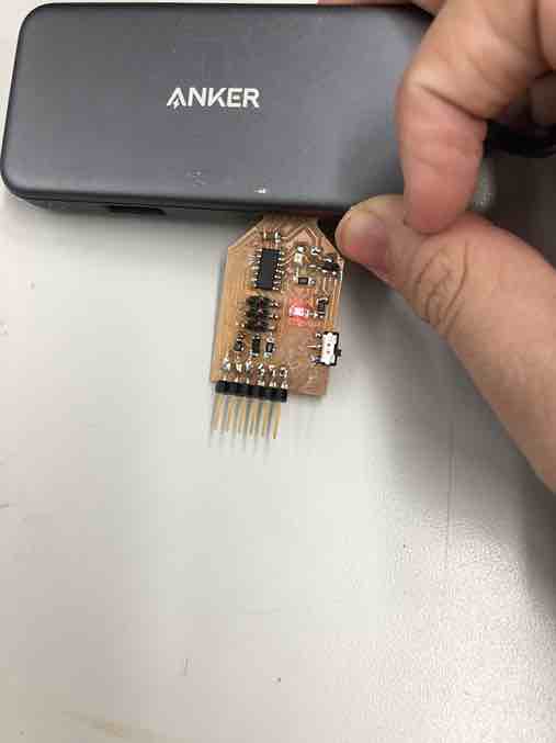
And this was the final product.
Overall I’m very proud of what I accomplished this week and I think it will benefit my final project a lot. This is a main component prototype of my final project since controlling brushless motors with the microcontroller is the toughest part of the project.
This week, I learned a lot about brushless motors and how ESCs work to control them. I learned about inrunner and outrunner motors: outrunners, the rotor is located outside the stator, inrunners, the rotor is located inside the stator. Also, I got exposure to calibrating ESCs and how to wire them up to control a brushless motor. Finally, I learned about serial communication to microchips and the FTDI Tx and Rx pins that I needed.
Week 10 Group Work
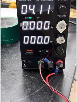
For this week Aarush, Jack, and I tested a servo motor using Jack’s servo tester board. We first hooked it up to a power supply and provided VCC and ground to the board, then we spun the potentiometer on the board and measured the power consumption. Here’s how it was wired up.
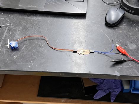
Here are the results in both image and video form
You can find more information about the group work for this week on the group site.
Week 10 Files
Click here to access the files for the week.