Week 8. Computer Controlled Machining (Mar 8)
Week 08 Assignment
-
make (design+mill+assemble) something big (~meter-scale)
-
extra credit: don’t use fasteners or glue
-
extra credit: include curved surfaces
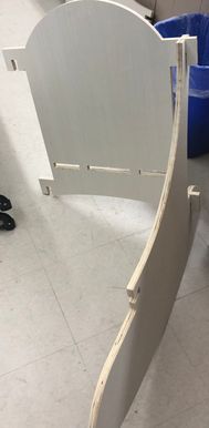
Press Fit Rocking Chair
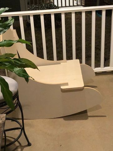
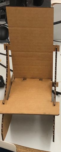
This is a picture of the final product.
Getting the Idea
This week, our assignment was to use the big Shopbot CNC machines to mill out something that’s larger than a meter. At first I had no idea what to make, because I really wanted to incorporate something for my final project into this week’s assignment. However after a talk with Dr. Fagan about my final project, I determined that my quadcopter as a whole would be smaller than a meter, and thus it would be too small for this week’s assignment. With this information I decided to build a piece of furniture instead.
I still had no idea which furniture I was going to make, and so I looked at previous Fab Academy pages for inspiration. From my research on previous students Graham Smith and Jack Hollingsworth, I noticed that people usually made various iterations of chairs and stools to sit on. From this I decided to do a chair as well, but to make it unique, I decided to do a rocking chair.
The original assignment for this week was just to make something larger than a meter, but my project is more than just that. Our lab actually makes it a requirement that our projects be press fit without using glue or screws. Additionally, I have included many curved surfaces, the most obvious would be the curved bottom of the chair that allows it to rock.
Version 1
For my first version of the press fit rocking chair, the idea was to base the design of the main chair portion off of Graham Smith’s press fit chair, and add a curved bottom surface under the legs so that the whole thing could rock. Additionally, I also pulled up images of rocking chairs on Google so that I could get a better sense of how the pieces would fit together. Specifically, this image and this image were very helpful.
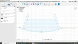
To start the design, I went back to Graham’s site and downloaded the chair.dxf file, and then brought it into Fusion where I could modify it. This is what the design originally looked like.
After bringing in the design for the chair I had to measure out some dimensions. Since every piece had to be slot fit, I decided to use Fusion 360 once again because I could use parametric design on most of the dimensions. The plan was originally to modify Graham’s dxf file, but after using the dimension tool and measuring in the design, I determined that Graham’s design wasn’t really suitable to modify. Thus, I simply started my own design, while using Graham’s design as a reference.
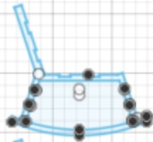
I started the design by first drawing the curve of the base, which I used the 3 point arc to do. I drew the same arc twice, one on top of the other, and then connected them with straight vertical lines

Next I moved onto the legs, which I created some tilted rods sticking out of the base of the chair. I thought about making the legs a slot fit piece as well, but then decided against it as it would result in lots of unnecessary work in the design. In my head, I planned to have a total of 8 slot fit pieces, with two sides, a seat, a back, and four leg connector supports. After drawing the tilted legs, I drew two horizontal lines across to mark where I would put my connector slots. This is what it looked like.
After that, I added in the slots, making sure they were 0.75 in x 0.75 in, since 0.75 inches was the projected thickness of my wood. Finally, I added in the tabs for the seat and back, again, making sure they were 0.75 in thick so that the pieces I designed would fit together. This is what the finished side of the chair looked like.
Next it was time to work on the two other kinds of pieces of the chair, the slot connectors and the back/seat. When I designed the side of the chair, I made it so that the back length and seat length were the same dimensions. This way, I could make one of those pieces in the design and duplicate them twice. I made the slots the same size as well, so I could design a single slot piece and then duplicate it four times. For actually designing the seat, I copied twice the jagged shape of the seat from the side piece design, and then inverted one of them. Then, I connected the two together with straight lines to form a seat that would fit into the tabs I had previously designed. Finally, to design the slots, I looked at this picture, and pretty much just copied the shape of its connectors: narrow, thick, narrow. These pieces looked like this.
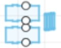
Finally, the completed design with all the pieces looked like this.
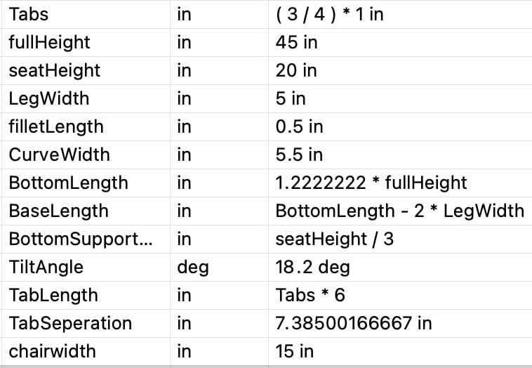
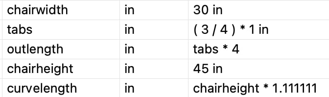
These are all the parameters I used on the first design.
After finishing the design, the next step was to perform a test cut on the laser cutter to prove that my chair would be stable and that all the pieces would fit together. However since I had designed everything to be cut on 3/4 inch thickness wood, I had to scale the entire design down to the thickness of cardboard in order to actually make sure all the tabs would fit. In my fusion file I went to the sketch, went to modify -> sketch scale, chose the sketch as my entities, and picked a random point as my scale point. To determine the scale factor, I had to perform some calculations. I knew that the wood thickness was 0.75 inches, and cardboard’s thickness was around 0.155 inches, and so I reasoned that the scale factor should be 0.155/0.75 ~ 0.2067.

I inputted the value and everything became smaller, which is exactly what I wanted. Next I converted it to a .dxf file through File -> Export -> Changing filetype to .dxf -> Export, opened it up in Corel, and headed to the laser cutter. Because I already have extensive experience with the laser cutter through Fab and engineering classes, this was no big issue for me. I decided to go with a sheet of 28 x 18 inch cardboard, while using the big Epilog Engraver machine. Since I’ve already covered how to use the laser cutter in previous documentations, I won’t be going into detail about the complete process of setting it up. This is a video of part of the cut.
These were the results of the first laser test cut.
When I tried to put the pieces together, however, everything just kept falling apart. This is caused by a few factors. Firstly, I think that the chair design by Graham Smith that I based the rocking chair off of was never meant to be a rocking chair. Although it may have been stable as a normal chair, when it was turned into a rocking chair, it was completely unstable since it was never meant to be used like that. Secondly, another reason I think my chair kept falling over is because it was made out of cardboard, which is neither a strong material nor an ideal one. Although it was only a test cut, and the wood I would be using would be much stronger and potentially be a stable structure, I did not want to take any chances. Since wood is so expensive, our lab’s instructor Mr Dubick restricted each of our students to only a singular 96 x 48 inch sheet of wood, and this meant that I only had one chance to get this chair right. I had two choices, to continue with that design by modifying it, or completely redesign the chair to be more stable, and I chose the latter option. From this week, I learned that sometimes you have to cut your losses and start over. However, my chair ended up turning out great, so I am ultimately glad that I switched designs.
Version 2
For this improved second version, I started off by doing further research on desigining rocking chairs. With some experience under my belt, I realized the mistake I made with the previous iteration, which is that I was trying to turn a chair, into a rocking chair, which is probably possible but not the best way to think about the chair design. Instead of turning a chair into a rocking chair, with this iteration, I decided to just design a rocking chair straightforwardly. This may seem like such a small change, but it produced a revolutionary result in my design. Another mistake I identified from the previous version was stability, and I needed this version of the chair to be truly stable, whether it was a test cut or a real cut. Thus with this new design I stressed stability as one of my most important factors.
Since I was not only designing a rocking chair, but a press fit rocking chair, I thought “Why not just find designs for press fit rocking chairs instead of just normal rocking chairs?”. This ended up being a pivotal idea because after a google search of “press fit rocking chairs”, I found this instructables on exactly what I was looking for. Finding this resource, I downloaded the pdf linked to the tutorial, and skimmed through it. This design for the rocking chair only has four parts: the left side, right side, back, and seat, with no need for extra support connectors. Another even better sign was that the person who made the instructable used 3/4 inch thick wood as well, so I knew I was on the right track with that. Then I started working on the design once again.
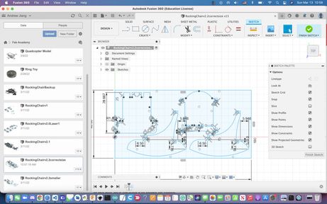
With the design, I began with the seat and back pieces, going off of the picture provided in the PDF. I used mostly straight rigid lines to model the shapes, keeping in mind the dimensions of the tabbed pieces and how they would mesh together with other pieces. Also, I relied heavily on parametric design, as I wanted every dimension to be dependent on the thickness of my material in case it wasn’t exactly 0.75 in when I went to go measure it, because then I could just change one dimension and not have to modify the whole design. This is what these two pieces looked like at first.
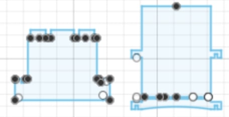
I also used the fillet command to remove some of the sharp edges on the two pieces. Thus those two pieces were complete. With the side piece of the chair, it wasn’t as easy to design since it include many curved edges which were impossible to get perfect with simple lines and points. To combat this I employed a different process; instead of just eyeballing the design like I had with the seat and back, I would import the image of the side piece sketch into fusion as a canvas, and then trace around the shape using the fit-point-spline tool. I started on the original tutorial pdf, and took a screenshot of the reference sketch.
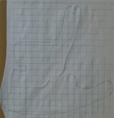
Then I went over to the fusion file, and went to Insert -> Canvas -> Insert from my Computer, and brought in the image while sizing it the best I could. Next I used the fit point spline tool combined with a few lines and arcs to trace out the shape of the piece. This is what that looked like.
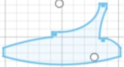
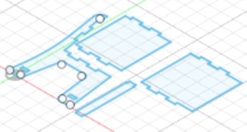
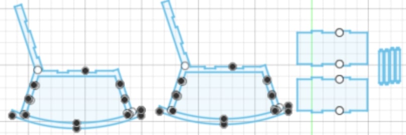
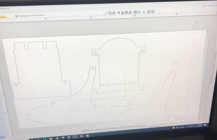
And this is what the entire design looked like.
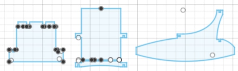
These are the parameters I used.
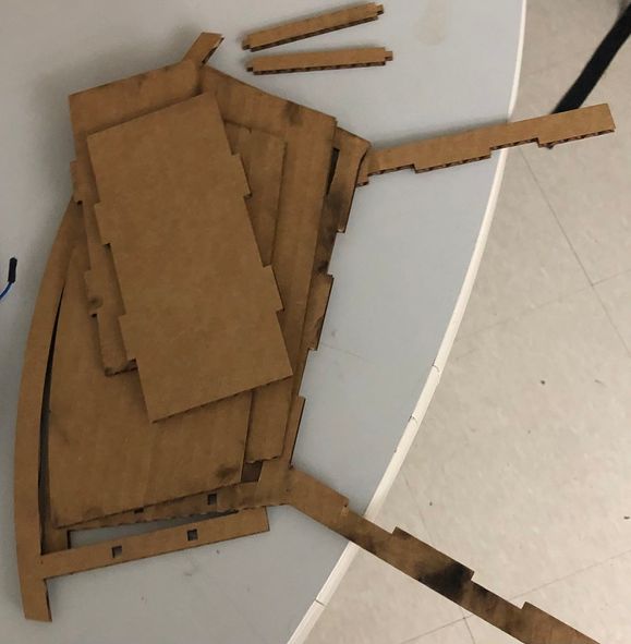
Once again, when the design was finished, it was time for another laser cut test. This is the result of the laser cut test, which was pretty successful compared to the previous one.
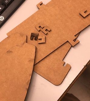
These were the pieces from the cut
This was the completed test cut. As you can see, it was much more stable and robust than the previous iteration. Not only is it a stable chair, but it could actually rock back and forth, and I was very satisfied with this design. To test its strength, I even placed a filled water bottle onto it, with it showing no sign of damage. Cardboard isn’t exactly a material known for its strength, so for a cardboard version of my design to be able to hold a water bottle, this basically meant that a wood version of my design would definitely be stable enough for a person to sit on it. After a painful but rewarding design process, it was finally time for me to use Aspire Vetric and begin the CAMming process.
CAM or computer aided manufacturing, is similar to CAD in that you use the computer to create a virtual design, hence the name. However, the main difference between CAD and CAM is that CAM is specifically used to control machines, while CAD can be used to control machines but also for other purposes. Because CAM and CAD are different processes, it took me some time to get the hang of the Vetric (VCarve) software. While I had some lectures by my instructors on how to use Aspire, I had never used it before this week, so I am definitely proud of my ability to pick it up so quickly.
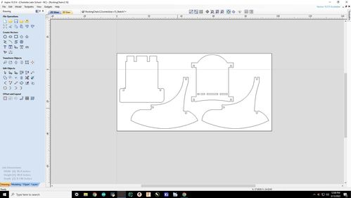
To begin, I once again exported the design as a .dxf file, and brought it into Aspire Vetric. The first time I brought it in and set the cut settings, I noticed that my pieces seemed way too big for the wood size, which was 96 x 48 in.
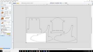
As you can see, all of my pieces were way to big for the actual cut. This issue confused me for a while since I was pretty sure I had designed the pieces to fit inside the dimensions of the wood in Fusion 360. To double check, I just went back to the Fusion file, and drew a rectangle around all of my pieces that was 96 x 48 inches.
I had to modify my pieces somewhat, such as making the straight top of the back piece into a curved top, but all in all every single piece indeed fit onto a 96 x 48 inch plane. I saved the modified design as a new .dxf file, and brought it back into Aspire, where I was again greeted with the same error. This time, I realized that the error was not a design error but an Aspire one, as it had somehow made my design way too big, and I needed to scale it down. Once again I found the scale factor by taking 0.75 in / current tab size, and sized everything down.
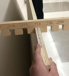
Now it was time for the Aspire setup. In the software, I went to the cut settings, and set the length and width as 96 x 48 in, the size of the wood sheet I was cutting on. For the material thickness, I used this slot fitting tool we have in our lab to gauge the true thickness of my material, which was 0.746 inch. Then I put that as the cut depth.
After that, I continued modifying the cut settings, zeroing off of the machine bed and removing the offset. Next, I closed out of the cut settings, went to the join tool, and joined each of my pieces together. Joining in Aspire is just like grouping in Corel Draw, and it helps you keep track of vectors that are all part of the same component. Then, I pulled up the fillet tool, and added dog bone fillets onto the inside of my slots. Dog bone fillets are essential for press fit structures since the machine’s circular bit cannot navigate sharp corners that easily, and thus it will mess up on some of the slot cuts if fillets are not added. After completing all the 2D processes, this is what the design looked like.
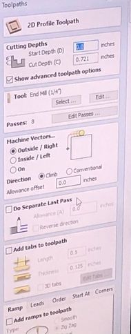
Now it was time to create the toolpaths. I made two different kinds of toolpaths, one for all the outside cuts, and one for the slots on the back of my chair. For each of the toolpaths, I went to the right side and brought up a profile cut. Then, I would edit passes from 8 to 4. The # of passes is how many times a machine will repeat the same toolpath, and too many toolpaths will result in a really long cut, while too little passes risks breaking the bit since with less passes means more material cut out on each pass. 4 passes seemed to be the right number for me, since the material cut on each was ~0.18, which was safe enough for a 0.25 inch bit. After editing the passes, I would add 4 tabs to each cut. Tabs are there to make sure your material doesn’t fly out when you are cutting, and you need to add them with every cut. The major difference between my two kinds of toolpaths was the cut location. On the outline cuts I made it outside the line since that’s how it was normally, but on the slot cuts I made it inside the line since that would actually cut out the tabs to be the size I designed them to be. This is what a toolpath looked like.
After finishing my toolpaths, I clicked on the little clock icon to estimate the cut time, and it said ~30 minutes. I went to preview all toolpaths and checked if everything looked good, which it did. Then I saved each toolpath as a seperate .sbp file and headed to the machine. Our lab’s shopbot is probably the most dangerous machine in our lab, so our instructors required us to follow the workflow and bring a partner with us. Here is our lab’s workflow which I followed. Since it was my first time using the Shopbot, fellow student Aaron Logan
Starting off the first step was to zero the z axis from the machine bed with the blue plate. That was the C2 command.
Next we zero the X and Y axes with C3.
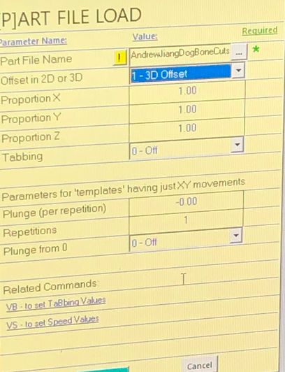
Then, we hit JZ4, raising the Z axis up. We load the wood onto the bed, and attach it down with screws. Next we have to set our origin point. I picked 2.5, 3 as my origin point since I was sure that wouldn’t hit any screws or go off the material. That’s the JZ(2.5, 3) command. Now hit Z2 to make that point your origin. Now we want to bring in the file and do an air cut, or a test cut that allows you to check if there will be a mistake. I went into the shopbot terminal, selected PART File LOAD, and brought in my slots toolpath first. To perform an aircut, I set it at a 3D offset.
After hitting ok, the machine prompted me to turn on the spindle, which I did by pressing the green button. Then I clicked START to start the aircut.
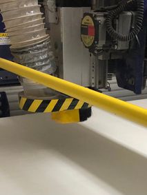
Following the successful aircut for the slots, I did the same thing for the outlines. The machine went up to this height after the aircut finished successfully.
Now that the aircuts were finished and successful, it was time for the actual cuts. I opened up the slots file in Shopbot again using PART File LOAD, and this time did not select a 3d offset before hitting ok. After starting the spindle, I hit start, and the machine began to cut out my dogbone slots.
After cutting out the slots, the machine moved back to the origin point I had set for it.
Next it was time to cut out my actual design. The machine started by cutting out the seat of the chair.
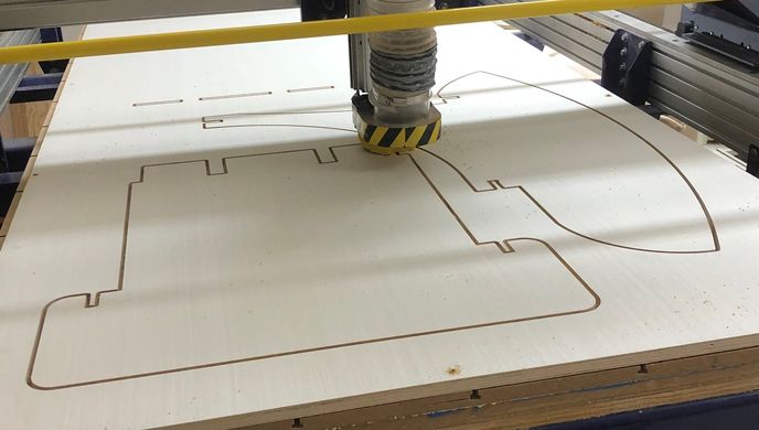
Then it cut out the sides.
Finally it cut out the back piece.
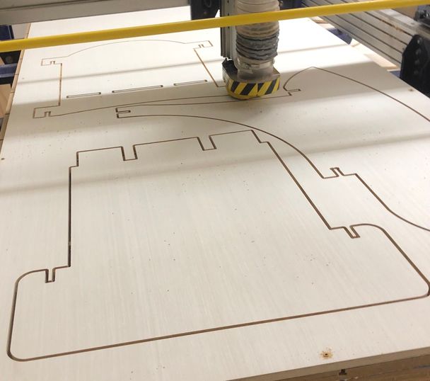
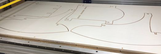
This was the finished cut
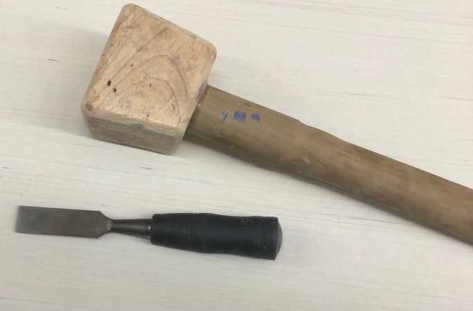
Next it was time for post processing, which included removing the tabs the machine had cut with a chisel and a mallet. I simply hammered the chisel into the tabs and they popped off.
Next I began to use the sanding tool to sand down my wood. For the small crevices, I used the metal file to scrape shards of wood off. Then after the sanding was done, I began to assemble my pieces.
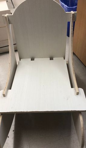
I really had no issues with the post processing work and it came pretty smoothly. This was the final product, which I am very proud of.
Week 8 Group Work
Toolpath
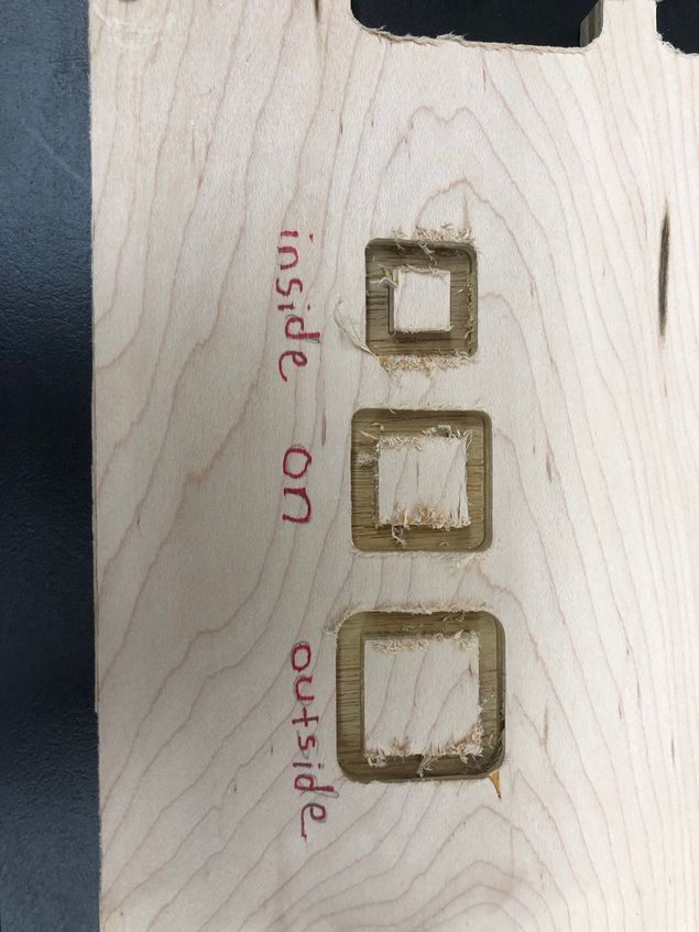
Aaron,Alaric and I worked on Shopbots’ different tool paths. The two types of cuts that we normally use in the lab are profile cuts and pocket cuts. Changing the tool paths can be accessed when the cut is a profile cut. After a vector has a toolpath, there are three options to select: Outside/Right, On, Inside/Left. Depending on what toolpath is selected, the machine will use the bit to cut along the line. To test this we created 3 1 in x 1 in squares each with a different toolpath . We made them a profile cut but decreased the cut depth so we could get a better visual.
They all used the small shopbot to cut them out, which we weren’t that familiar with. Because the machine was off, we knew we had to warm up the spindle before cutting, but we were not sure how. Searching it up, we found shopbot’s official documentation on how to set up the machine, and we pretty much just followed that.
This is us warming up the spindle.
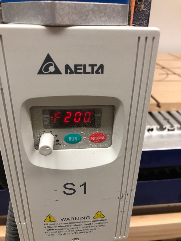
After warming up the spindle, we had to set the the spindle frequency to 200 rpms
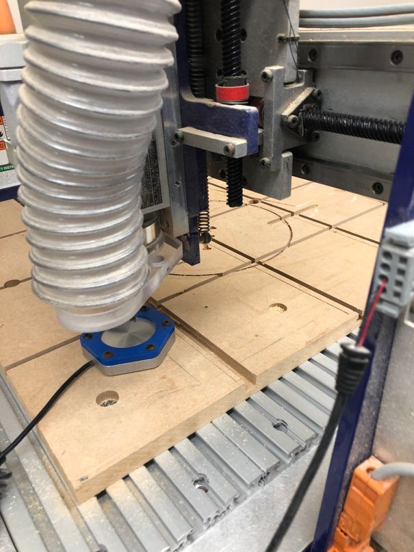
Next it was time to set up the cut, which we could follow the exact same process as the large shopbot. This is us calibrating the thickness with the bed plate.
After setting up the machine, we performed the air cut, which looked fine.
However, the first few times we tried to run our toolpath, we ran into some issues with the machine cutting way too deep, so much so that it would cut out the tabs onto the bottom board.
We finally realized the problem after a few tries, which was that the Desktop machine couldn’t go as high for the Z axis as the big machine. When we were trying to calibrate the Z then, the machine thought that it was higher than it actually was, and so it was cutting into the bottom board. Thus we ran it again, this time taking the lower Z value into account, and it worked perfectly. This was the result of our tests.
You can find more information about this week’s group assignment on our group site
Runout
Aaron, Alaric and I also worked on the Shopbots runout. There are two types of runout, axial and radial. In order to test this we had to use a specific tool to measure the runout as a group member spun the spindle by hand. After finding the tool and setting it up, we made sure to shut off the spindle by taking the key out. Then we held the probe up to the spindle, and the group read the output measurement as one member spun the spindle. These were our results
Week 8 Files
Click here to access my files from this week.