8. Computer controlled machining
This week I learned how to use the cnc machine to produce large projects such as furniture using slot fit to join pieces.
All files used can be found here
Inspiration
Most of my initial ideas for the week were mostly simple chairs, stools, and tables, but I wanted to make something more interesting, so I started browsing the sites of last year’s fab students. I found Alberto Gonzalez’s site with his race car chair and thought it would be very nice to have such a horizontal chair and make it myself.
Design in Cuttle
I first designed the 2d shapes parametrically in cuttle.
I started with 3 lines to form the basic structure of the back of the main body. The lengths of these were determined by measuring myself head to waist then waist to knee then knee to foot and then adding a few inches to each, and each had its own parameter so that it chould be changed easily later if needed.
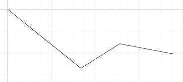
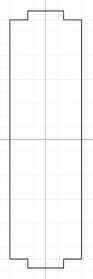
To make this have more of a curve, I grouped the 3 lines then used the round corners modifier. I also added the outer frame of the rest of the body.
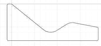
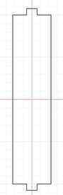
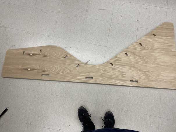
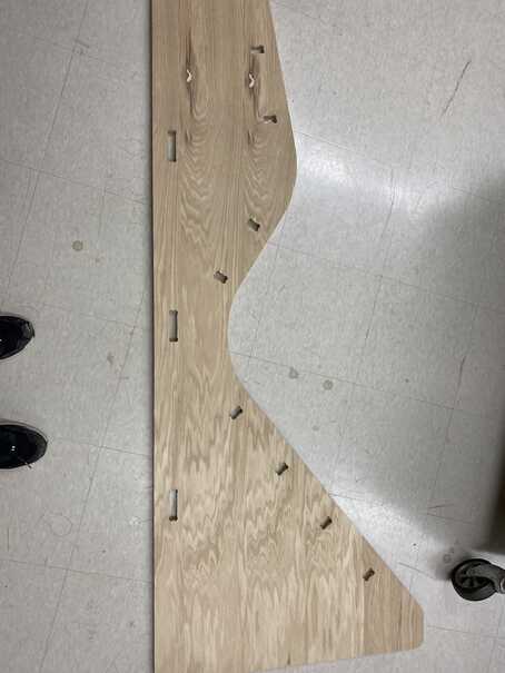
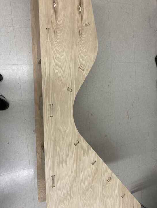
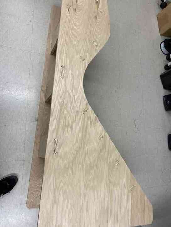
I then added tabs along the back.
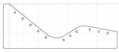
I finished off the design of the body with tabs along the bottom for stability.
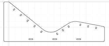
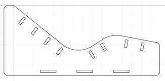
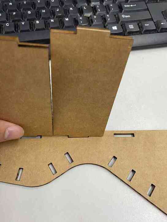
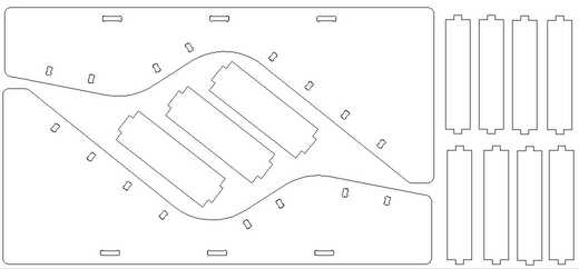
To make the bridges between 2 pieces of the body, I made rectangles of different widths and added tabs to them that would correspond to those on the body. To join the tabs with the main rectangles to form a single path on the outside, I used the boolean union moderator.
Laser Cut Test
To make the design fit on a laser cutter, I simply changed some parameters to make things smaller and decrease the number of tabs along the top.
This, however, could not be put together because the sizing down made the bottom tabs closer, and I did not make the boards that go across small enough to fit.
So I changed some parameters again to make the bottom boards and the tabs smaller, and it turned out nicely.
Aspire Design
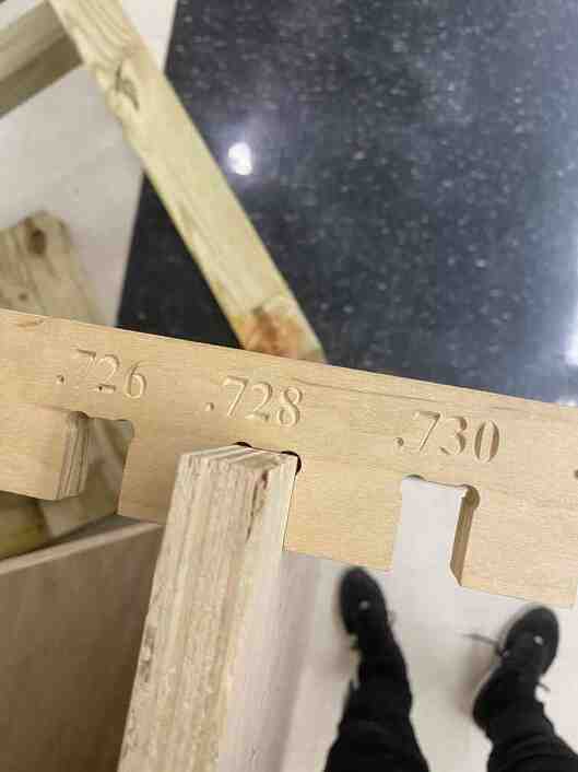
For the material settings, I had it as 96x48 inches, which are the dimensions of our lab’s bigger shopbot. I also measured the thickness of my wood to be 0.7225 inches although there was some tiny variation. Due to these possible small variations, I set the zero to be from the machine bed so that it would not cut into the bed. I also used the tab size comb in our lab to determine how big the tabs should be and adjusted the parameters in my design accordingly.
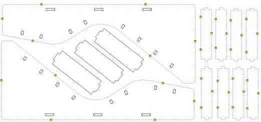
When I exported my design as an svg and pulled it into aspire, however, I was only 2 pieces away from being able to fit my entire design on a single sheet of wood, so I went back and resized some parameters and pulled it back into aspire. I also added dogbones to the slots to acount for the bit being circular and cutting tangent to the vectors resulting in some corners not being cut away enough.
I then made the toolpaths with the outer edges as profile cuts set to the outside and the inner slots set to inside profile cuts. I also added tabs.
Cutting
I followed this workflow provided by my instructors to use the machine.
To observe safety precautions, I had goggles on at all times, I had the spindle off whenever working on the machine bed, I called out to those in the room whenever I moved the machine, and I had ear protection whenever the spindle was running.
Homing the x and y axes meant using the homing x and y axes using proximity switches command (C3), and homing the z axis meant placing the z home plate under the bit and running the home with z plate command (C2).
I then put the wood on the machine bed and fixtured it in with screws. After that, I jogged the machine to (3, 3) and set that as the zero for x and y so as to have an offset and prevent the cut from going into the screws.
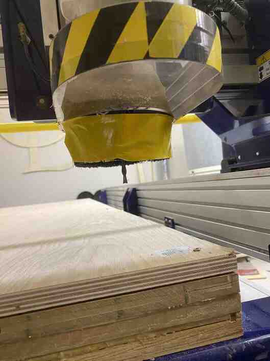
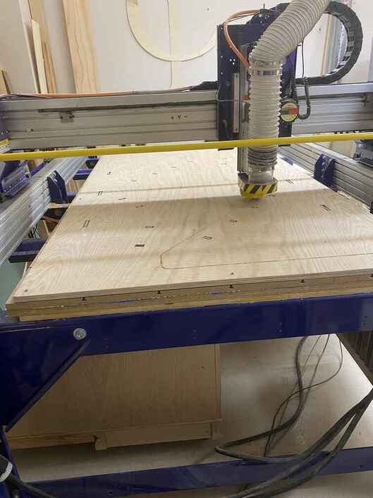
I did an air cut with the profile cuts of the outer edges, and I had the idea to make a separate file for the air cut with only 1 pass to have it go faster while still getting an idea of how the machine will move.
I then started the cut for the slots.
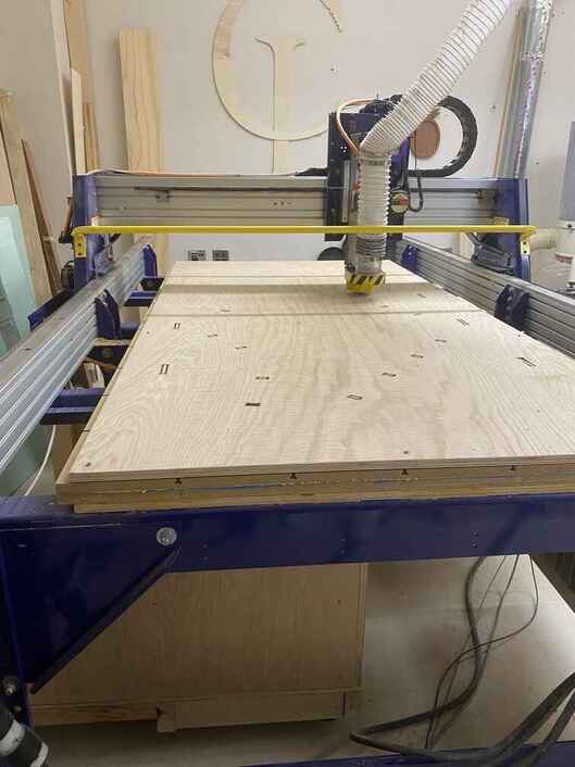
After that, I started the cut for the outer edges.
Postprocessing
The cut turned out well althoug after removing the wood from the bed, the tabs of 2 pieces could no longer hold it to the wood.
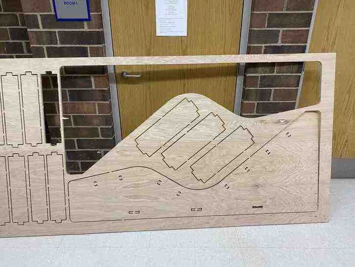
I then removed the tabs with a mallet and a chisel to remove the pieces from the wood.
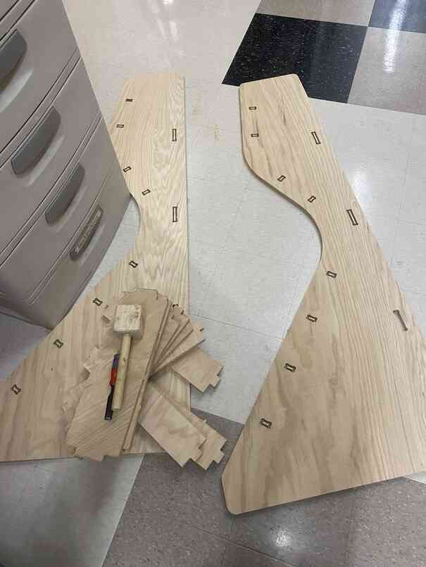
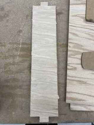
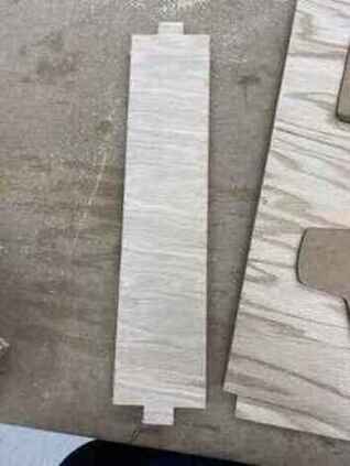
I then used a power sander to sand down the remnants of the tabs on the outside of each piece, and below shows before and after sanding.
I did the same for the body pieces, but I also had to hand file down the remnants of the tabs for inside the slots since the slots were so small.
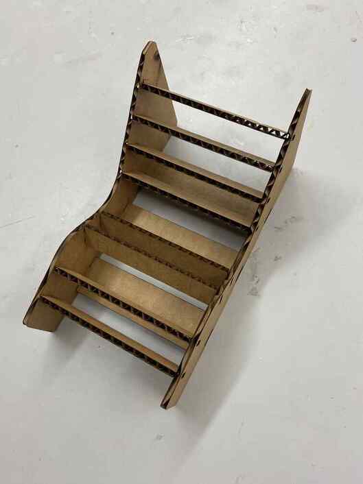
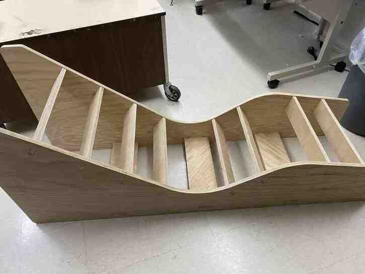
To put it together, I started by putting in all the bridge pieces on one body.
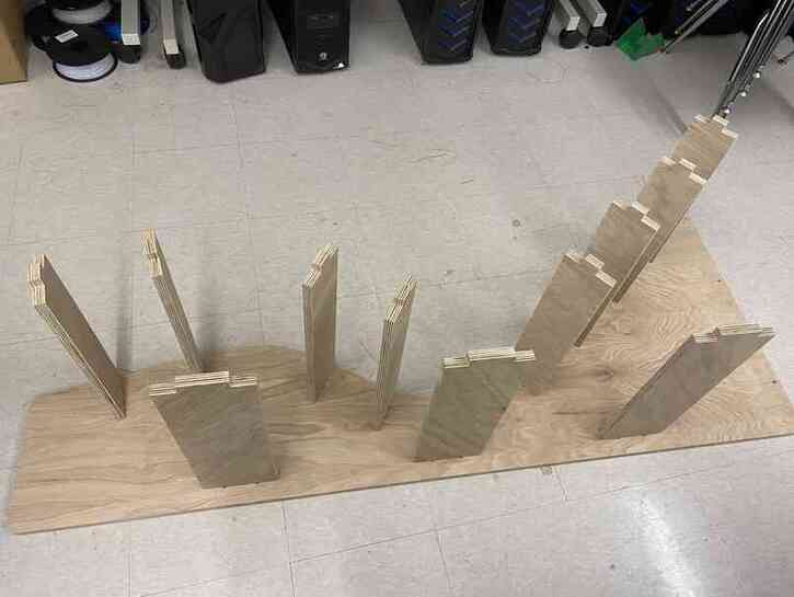
I then put the other body on top and aligned the tabs.
To finish, I used a mallet and knocked the body in.
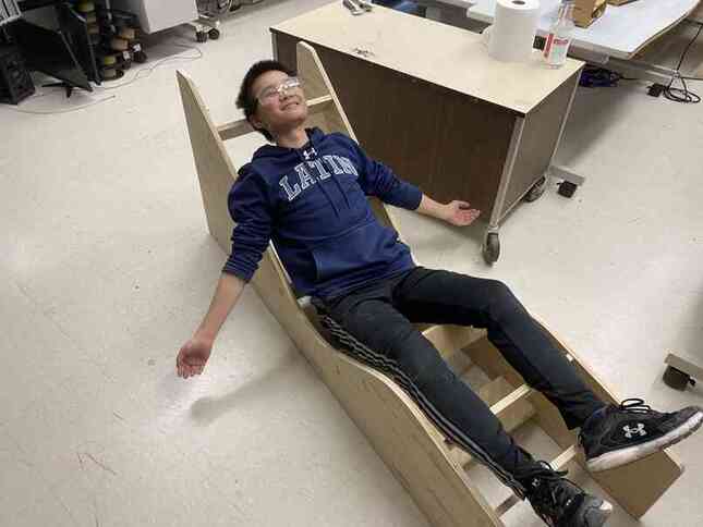
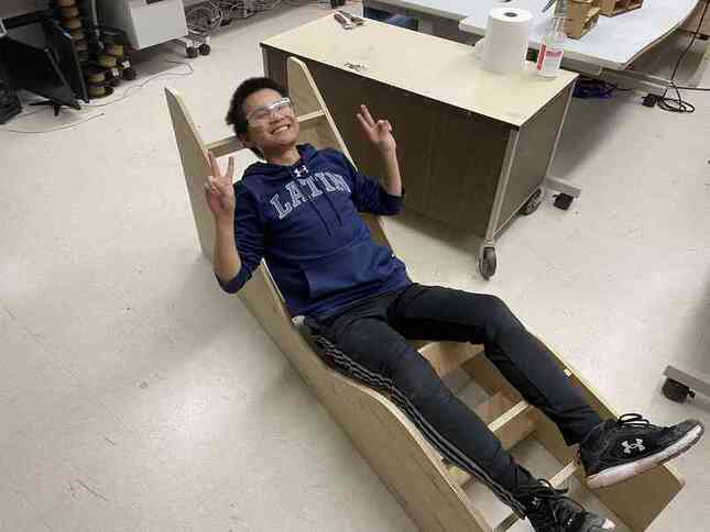
I then flipped it right side up and tested it.
Group Site
Our group work for this week can be found here.
I worked on testing toolpaths and runout using inside and outside profile cuts and a pocket cut for toolpaths.