0. Pre-Fab Prep
Learning Surface Mount Soldering
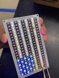
I learned surface mount soldering by soldering LEDs and resistors to the board below, and I prefer the method of putting solder on one pad then move the piece into the pad and then solder down the other pad. Two of the LEDs I soldered on got burned though, and I could not remove them with just the soldering iron or the wick, so I used a heat gun to remove them applying preassure with tweezers.
Assembling 3D Printers
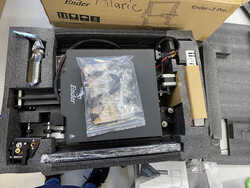
In assembling the Ender 3 Pro, I first checked the parts list and made sure I was not missing any parts
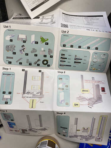

Then referring to the instructions and this video, I started assembly.
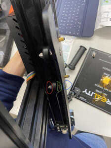
In the first step of tightening the bed to the y axis, I made a few mistakes.
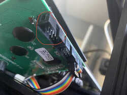
Referring to the image below, I was tightening the bolt circled in red when I should have been tightning the one circled in green. As such, it wasn’t tightening, so my instructor, Mr. Dubick, suggested that it could possibly be that the screw (circled in blue) was stripped and that I could detach the bed and hold the other side in place, but it still did not work. I then tried it on a bed from the spare parts, and it still didn’t work. With the advice of my classmates, I found out that I was actually tightening the wrong bolt.
For the second step of attaching the side mount, I had put on the wrong type of mount, which I found out when I tried to attach the z axis motor and could not since there were no screw holes on the mount I put on, so I had to change that to attach the motor.
The wrong side mount had 1 screw hole in the circled region.

The right one had 2

Then, I tried to attach the side switch shown below, but I could not since the plastic of the bottom t nut was deformed, so I grabbed one from the spare parts.
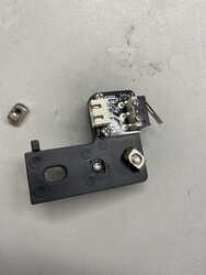
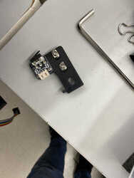
The side switch (shown directly above) I got from the spare parts worked, and I attached it. I also attached the extruder to the bar going across and the side mount. When checking if the extruder was parallel to the bed, however, I noticed that the side mount was twisted, and so I straightened it.
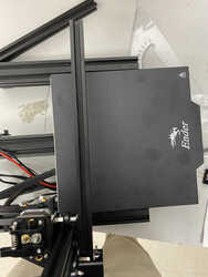
Extruder arm not parallel to bed
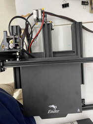
Extruder arm parallel to bed
I attached the opposite side mount, and my classmate, who is a previous fab graduate, Drew Griggs advised me to look more at the paper instructions of the printer rather than following the video so much, and he lended me a hand supporting pieces to make it easier to screw in. The process went mostly smoothly with attaching the power source, the top frame, the electronics, and the LCD display.

At first I had attached the cord going to the LCD display into the wrong port, but I quickly corrected it. The picture below displays the cord in the correct port and circled in red where I mistakenly had it.
I then took it home, but when I tested it there, the z axis stopped working. I thought it could be that the lubricant was not evenly spread, so I tried spreading it, but that did not work. I then just took off the thread going into the motor and put it back on, and it worked. Below are tests of the extruder and the motors.
Leveling 3D Printer Bed
After assembling the 3D printer I had to level the bed following this video. I downloaded the files in the video on this site which was in the description, and I copied them over to the ssd card to use with the printer. I then tried to run the CHEP_M0_bed_level.gcode file, but it didn’t work and just moved the extruder through without stopping at each corner to act as a benchmark for leveling the bed, so I tried running the CHEP_M25_bed_level.gcode file, and it worked. At each corner I took a small piece of paper and passed it between the bed and the nozzle of the extruder, and I adjusted the corner with the wheel under the bed until the paper passed through with a bit of resistance (clockwise moves the bed up and counterclockwise down). The videos below show the states before and after adjusting a corner.
Corner before leveling
Corner after leveling
Also, with the paper, make sure to use scissors to cut out a small piece rather than ripping it off since ripping off a small piece makes the piece bent while cutting keeps it flat.
I then ran the CHEP_bed_level_print.gcode file to test the leveling. I ran my finger accross the thin lines of filament printed, and if it rubs off then that corner is not close enough to the nozzle, but if the line seems dull, it is too close.