5. Electronics production
This week I learned how to mill a PCB board and how programmers work.
All files used can be found here
Electronics Preparation before Week
412 Board Blink Code Hardware
I learned from my instructors, Mr. Dubick and Dr. Harris how to use an arduino as a programmer for a 412 board.
First to set up the 412 board I soldered it onto a breakout board. I made sure to have the side of the breakout board with the thicker pads facing up when soldering pins onto it.
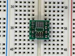
Here you can see the difference between the thin and thick pads
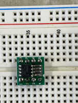
Here you can see how I positioned the breakout board
I then soldered down 2 corners (pins 3 and 4) to keep the board steady
Then I soldered the rest of the pins
Next I put solder on one side of the pads
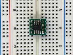
I then positioned the 412 board like so with the indentation in the corner closest to pin 4 and soldered it on
Then I soldered on the 412 board to the pads on the opposite side
Next I wired it connecting pins 1 and the arduino power to the power on the breadboard, connecting pins 8, the ground on the arduino, and the ground of a blue LED to the breadboard common ground, connecting pin 7 to the power of the LED, and connecting pin 6 to pin 6 on the arduino as a UPDI connection. The arduino was already confirmed to be a working programmer and was used to test the hardware, and after uploading a blink code to the 412 board, it worked and the LED was blinking
Arduino Uno as a Programmer for 412 Chip
After confirming that the hardware for the 412 chip was good, I then made an arduino uno into a programmer with instruction from by instructors, Mr. Dubick and Dr. Harris. I also used instructions and resources from these sites: electronics lab, sheek geek, dazzy package, and this github repo.
First, I opened the arduino IDE and went to file then preferences under that and in the Additional Boards Manager URLs, I pasted the following link: http://drazzy.com/package_drazzy.com_index.json.
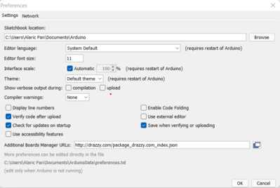
Then I went to tools then board then board manager and installed the megaTinyBoard library to be able to use the 412 chip
Next, I downloaded the code from this github repo. I moved the zip file to the desktop, and I extracted the file. This created a folder called jtag2updi-master within another folder with the same name. Since the arduino IDE wants arduino files to be in a folder with the same name as them, I renamed all the jtag2updi-master folders to jtag2updi. Then, I opened the jtag2updi arduino file in the folder, and I uploaded it to the arduino.
Now that the arduino is a programmer, I opened another sketch with the following blink code:
void setup() {
  // initialize digital pin LED_BUILTIN as an output.
  pinMode(4, OUTPUT);
}

// the loop function runs over and over again forever
void loop() {
  digitalWrite(4, HIGH);   // turn the LED on (HIGH is the voltage level)
  delay(100);                       // wait for a second
  digitalWrite(4, LOW);    // turn the LED off by making the voltage LOW
  delay(100);                       // wait for a second
}
I then under tools changed the board to the ATtiny 412 chip and uploaded the code, and it started blinking faster since the previous blink code that was uploaded had greater delay values.
Surface Mount Milled Board with 412 Chip
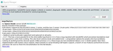
After recieving a milled board from my instructor, Mr. Dubick, I followed the wiring diagram below from this site.
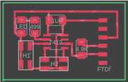
When soldering on the 412 chip, I put solder on one of the corner pads, and then I moved the chip onto it, soldering it on. I then soldered the opposite corner then soldered the rest.
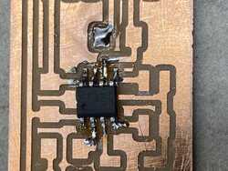
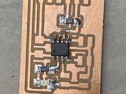
I then soldered the LED and the 2 resistors
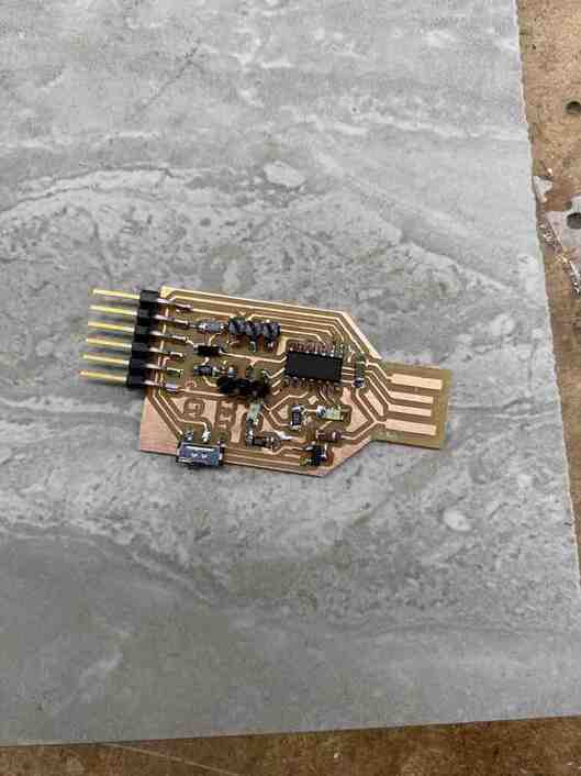
Then after soldering on the capacitor and header pins, leaving out H1 and H2, and repeated the steps above for using an arduino as a programmer with pin 6 as the updi. After uploading the code below, it worked.
void setup() {
  // initialize digital pin LED_BUILTIN as an output.
  pinMode(0, OUTPUT);
}

// the loop function runs over and over again forever
void loop() {
  digitalWrite(0, HIGH);
  delay(1000);
  digitalWrite(0, LOW);
  delay(1000);
}
Group Site
For our group site, I worked on defining key terms including feed, speed, plunge rate, depth, and tooling and contributing to the workflow for our milling machine.
SAM Chip Programmer 1
Milling the Board
I used the design and files from my instructor, Dr. Harris’s, website. It contains a link to a github repo with the files in the Gerbers folder.
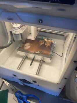
When milling, I referenced this workflow provided by my instructor, Mr. Dubick, and created a workflow on our group site.
After downloading the file, I took a board and put strips of nitto tape on the back and placed it on the bed, making sure to press it down hard to the bed. I then wiped it with alcohol.
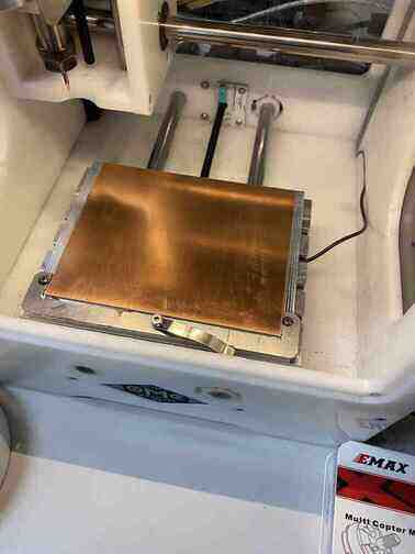
I opened the file in Bantam Tools and added the 0.005” PCB engraving bit in addition to the 1/32 flat end mill bit to the tools and changed the both the trace clearance and trace depth to 0.25mm. I then changed the bit to 0.005” PCB engraving bit and located the tool.
I then moved the clip at the front of the bed onto the material and in Bantam Tools went bitbreaker > probe material thickness.
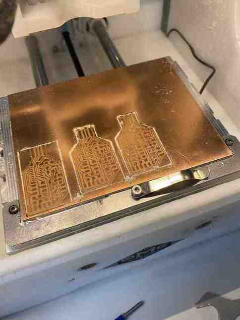
I then started the cut after moving the clip off.
After it finished with the 0.005” bit, I changed the bit to a 1/32 flat end mill bit and located the tool and continued the cut.
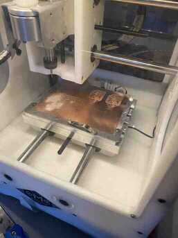
I then realized that the outline of the cut was just a large rectangle around the traces rather than an outline that would allow usb connection, so I recut working with my classmate Jack since he needed a board as well and the other machines were already working, so we combined 2 boards in 1 cut. To get the correct outline, I downloaded both the Fab11C-Edge_Cuts.gm1 and Fab11C-F_Cu.gtl files rather than just Fab11C-F_Cu.gtl from the github repo and opened Fab11C-F_Cu.gtl making sure the outline was Fab11C-Edge_Cuts.gm1.
I kept the material on the bed so as to make sure that I could accurately position the new boards to avoid the cut board on the material already and did the cut.
Next, I washed the board under water and dried it.
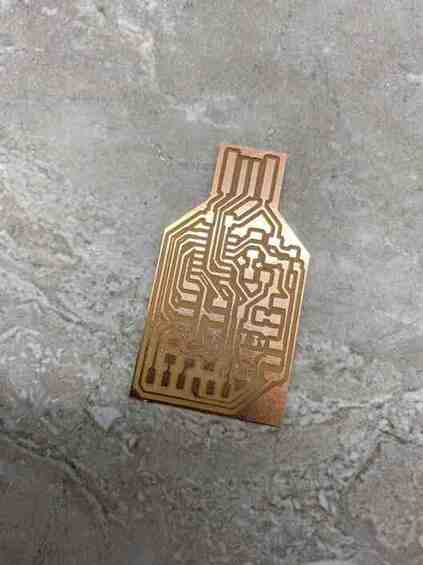
Soldering the Components
I gathered all the needed components on the components list in the BOM.csv file on the github repo using a 1 kohm resistor instead of 1.2.
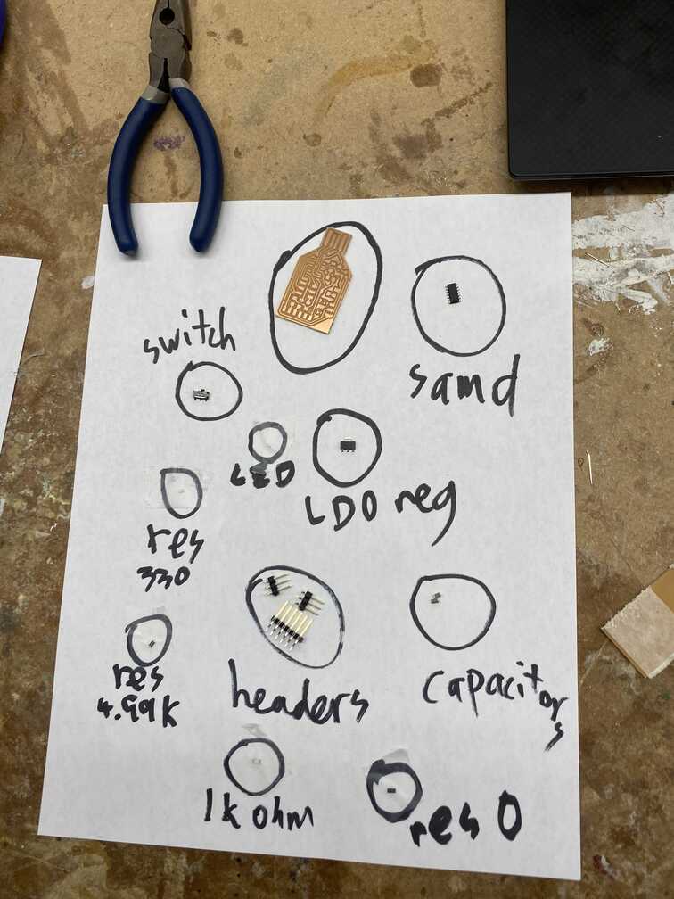
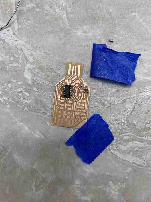
I looked at the render.png file in the SVG and PNG exports for Fab mods milling folder in the github repo. I then went to solder the SAM chip onto the board, and my classmate Jack suggested that I tape down the board to make it easier. I put solder on 1 pad in the corner and heated it to put the chip on and secure it.
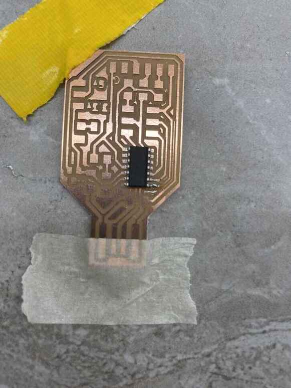
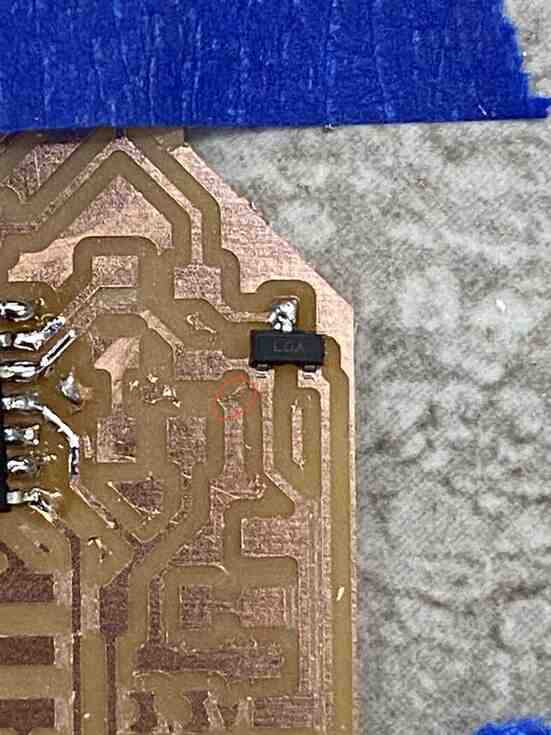
I then soldered the rest of the pins on the chip as well as the capacitors and the horizontal headers when I noticed that the LDO regulator that I had gathered did not fit onto the pads, so I found a different one that did and soldered it.
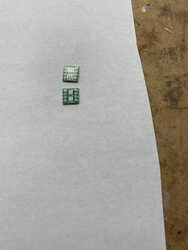
A previous fab graduate Graham Smith pointed out to me that the 330 ohm resistors I got were too small (the same was true for the LEDs as well), so I got bigger ones to solder, and the size difference can be illustrated in the following image:
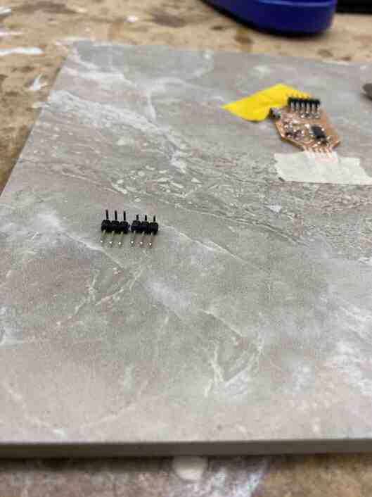
When I went to solder the header pins, I decided to trim them down a bit with wire cutters to prevent it from bridging when soldering.
After soldering everything, my instructor Dr. Harris told me that I would have to trim away the copper on the edges of the side that goes into the usb connection to prevent it from short circuiting the usb port.
Software
Dr. Harris used my board as a demo for the process of pushing code to it to make it into a programmer by first connecting the board to an ATMEL-ICE and downloading edbg and the arduino firmware making sure to put them in the same folder, then running the following command opening the command line in that folder:
edbg-windows-r24.exe -bpv -e -t samd11 -f sam_ba_Generic_D11C14A_SAMD11C14A.bin
and then in the arduino IDE pasting https://www.mattairtech.com/software/arduino/package_MattairTech_index.json into file > preferences > additional board manager URLs and in tools > boards > board manager, installing the one for SAMD by MattairTech, and finally uploading the following code to confirm that code can be sent to the board with the arduino IDE:
int led = 2;

// the setup routine runs once when you press reset:
void setup() {
  // initialize the digital pin as an output.
  pinMode(led, OUTPUT);
}

void loop() {
  digitalWrite(led, HIGH);   // turn the LED on (HIGH is the voltage level)
  delay(1000);               // wait for a second
  digitalWrite(led, LOW);    // turn the LED off by making the voltage LOW
  delay(1000);               // wait for a second
}
SAM Chip Programmer 2
So that I could go through the software process again, I went through the entire process again. Also, I had given my first board to the lab to be converted to serve the function of the atmel ice since the atmel ice requires a cord that Dr. Harris put together that was fragile, so using the board as the atmel ice could be easier with jumpers.
Milling and Soldering the Board
I milled a board in the same process as the first with the same settings.
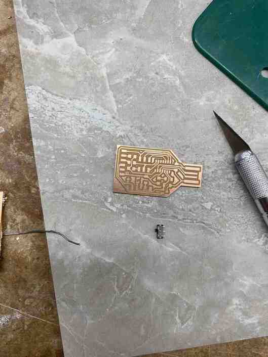
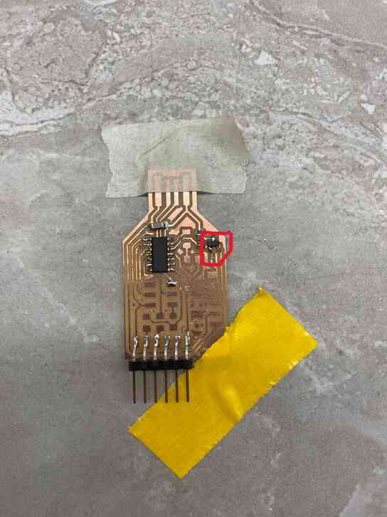
I then soldered some of the components on when I noticed that a trace was bridged.
After cutting that away, Dr. Harris pointed out to me that some of the narrow excess copper between the traces could cause bridges, so I cut those away as well.
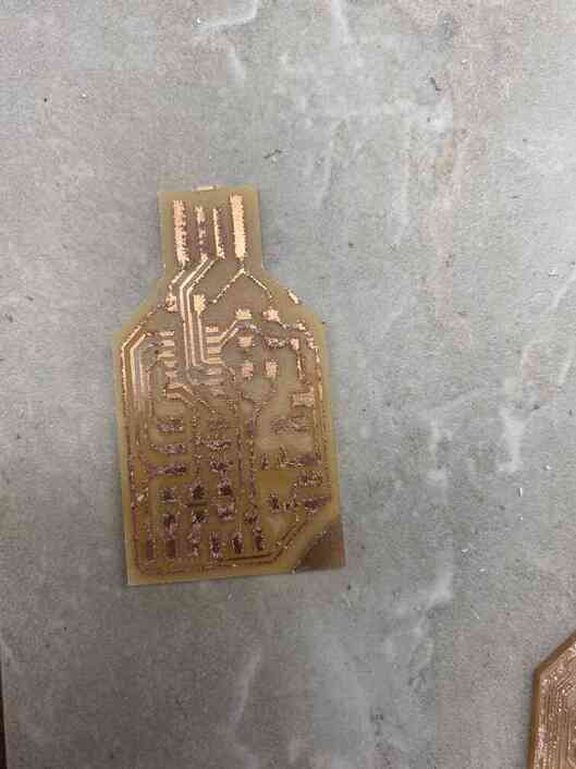
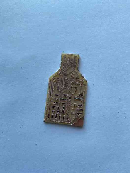
I then noticed that I soldered the chip on backwards, so I milled another board with my classmate Jack with the trace clearance at 1mm and trace depth at 0.25mm to have the machine cut away all excess copper between the traces, but it milled away too much and some of the traces looked thin and ripped.
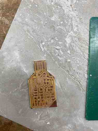
We then milled boards with trace clearance at 0.3mm instead and cut away the copper surrounding the end manually.
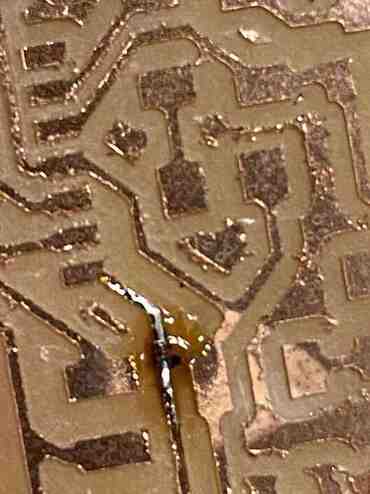
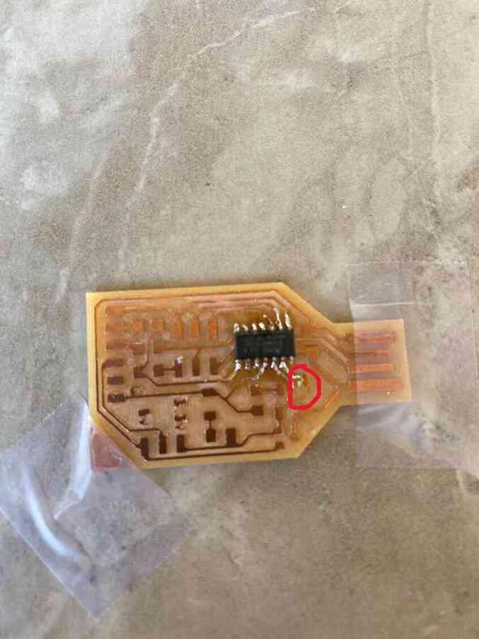
When I was cutting away some of the excess, however, my hand slipped, and I accidentally cut the trace.
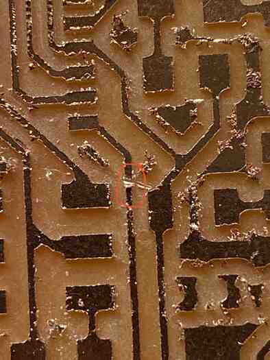
My instructor, Dr. Taylor, told me that I could attempt to recover the trace by seeing if I could put some solder on the point and bridge across, but in this case, it just put solder on both sides and charred the middle.
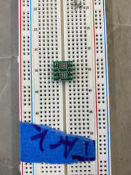
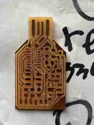
I then milled 2 boards, one with trace clearance at 0.25mm and the other at 0.27mm since I thought the 0.3mm cut did have some weak traces. During the cut, I noticed that I had forgotten to take off the clip from probing material thickness, and the bit might get close to it, so I paused the cut and moved the clip off and then resumed.
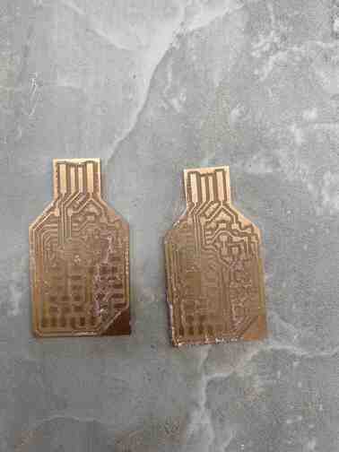
In the image above, the board on the left is 0.25mm trace clearance and the right is 0.27mm. Afterwards, I decided to mill more boards since I would not have access to the lab for the next couple days and wanted to make sure I have backups in case I rip a trace soldering at home. Mr. Dubick showed me a board that looked great which he milled with a trace clearance of 2.5mm with the following bits: 0.005” PCB engraving bit, 1/64 flat end mill, and 1/32 flat end mill. I used the same bits with trace clearance 2mm and trace depth 0.2mm.
I then milled one with trace clearance 1.5mm.
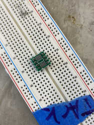
Afterwards I cut away the excess copper fuzz that gathered around and between the traces of both boards.
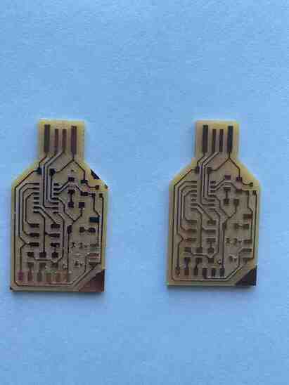
In the above picture, the board on the right was the one with trace clearance 2mm while the other had trace clearance 1.5mm.
I then started soldering the board with 2mm trace clearance, and I took the suggestion of my classmate Nicholas and taped down the chip to the board to solder the first pin then removed the tape and soldered the opposite pin.
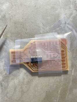
Then, when I was using the solder sucker to remove a solder bridge, it ripped a trace.
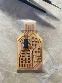
I then switched to the board milled with 1.5mm trace clearance and soldered everything on.
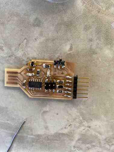
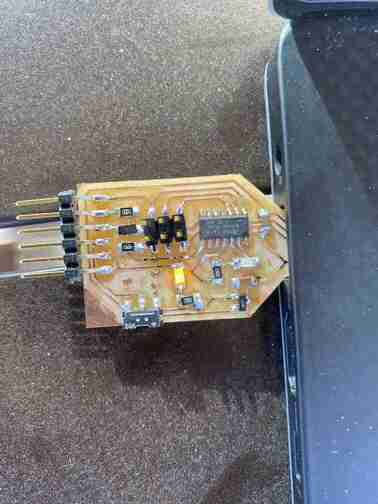
I put it into the usb port of my computer to test if it could get power, and it could, indicated by the LED that turned on.
Software
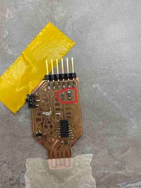
I used my first board which was made to serve the purpose of the atmel ice to allow the board to communicate with a computer. Following the wiring diagrams displayed below found on Dr. Harris’s website with pin 1 as Vcc, pin 2 as DIO, pin 3 as GND, pin 4 as CLK, and pin 10 as RST.
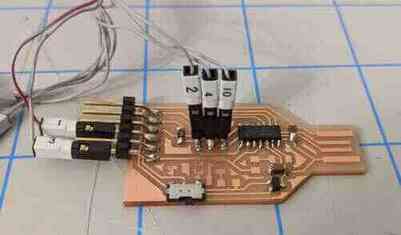
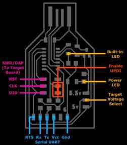
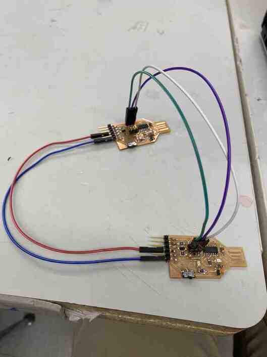
In the above image, the board in the back is the board acting as the atmel ice.
I then downloaded edbg and the arduino firmware and put them in the same folder. Then I plugged the atmel ice board into the usb port of my computer and ran the following command found on Dr. Harris’s website with the command line in the fold:
edbg-windows-r24.exe -bpv -e -t samd11 -f sam_ba_Generic_D11C14A_SAMD11C14A.bin
That, however, returned an error.
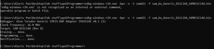
As you can see above, to resolve this I realized that I had downloaded a more updated version of edbg, so I just changed edbg-windows-r24.exe to edbg-windows-r29.exe, and that worked.
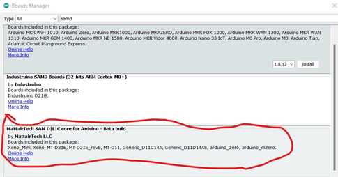
In the arduino IDE I pasted https://www.mattairtech.com/software/arduino/package_MattairTech_index.json into file > preferences > additional board manager URLs, and in tools > boards > board manager I installed the library for the SAM board by MattairTech.
I then went to tools > board > MattairTech SAM > Generic D11C14A. I then uploaded the following code to test if it could send code.
int led = 2;

// the setup routine runs once when you press reset:
void setup() {
  // initialize the digital pin as an output.
  pinMode(led, OUTPUT);
}

void loop() {
  digitalWrite(led, HIGH);   // turn the LED on (HIGH is the voltage level)
  delay(1000);               // wait for a second
  digitalWrite(led, LOW);    // turn the LED off by making the voltage LOW
  delay(1000);               // wait for a second
}
Afterwards, I made the board a programmer by uploading the following code to it:
void setup() {

   SerialUSB.begin(0);
   Serial1.begin(57600, SERIAL_8E2); //Adjust baud rate and use SERIAL_8N1 for regular serial port usage

  /*Trigger the reset line for the UART.
 This is supposed to trigger the target board's reset as if it is the RTS line. I couldn't figure out the SERCOM setting for
this in the SAMD11C datasheet*/
  pinMode(5, OUTPUT);
  digitalWrite(5, LOW);
  delay (100);
  digitalWrite(5, HIGH);
}

void loop() {
   if (SerialUSB.available()) {
      Serial1.write((char) SerialUSB.read()); //Send stuff from Serial port to USB
   }
   if (Serial1.available()) {
      SerialUSB.write((char) Serial1.read()); //Send stuff from USB to serial port
   }
} //end loop
When I tried to upload code to the LED blink board in an above section under the prep I did before the week, it gave the following error:

I realized that my programmer setting in the tools was wrong as it was still the jtag2 one that I had used with the arduino, so I changed it to SerialUPDI - SLOW: 57600 baud, any platform, any voltage, any adapter under tools > programmer.
I then uploaded the following code:
void setup() {
  // initialize digital pin LED_BUILTIN as an output.
  pinMode(0, OUTPUT);
}

// the loop function runs over and over again forever
void loop() {
  digitalWrite(0, HIGH);
  delay(200);
  digitalWrite(0, LOW);
  delay(200);
}