13. Input Devices
This week I worked on defining my final project idea and started to getting used to the documentation process.
Final files used can be found here.
3d Hall Effect Sensor
I chose to use a 3d hall effect sensor, specifically the TLE493DA2B6 since my final project would involve using a magnet, and the sensor could be used to track the position of the magnet when engaged whether for constant tracking or for zeroing.
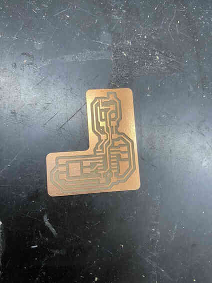
PCB Design Attiny412 (failed)
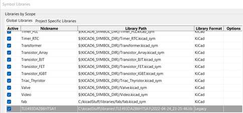
To start, since both the default libraries and the fab library for kicad did not include my input, I downloaded one from this site.
After downloading and unzipping the library, I moved it to a safe directory on my computer and opened the symbols library manager in kicad and added it, and I did the same with the footprints library manager (both under the preferences menue).

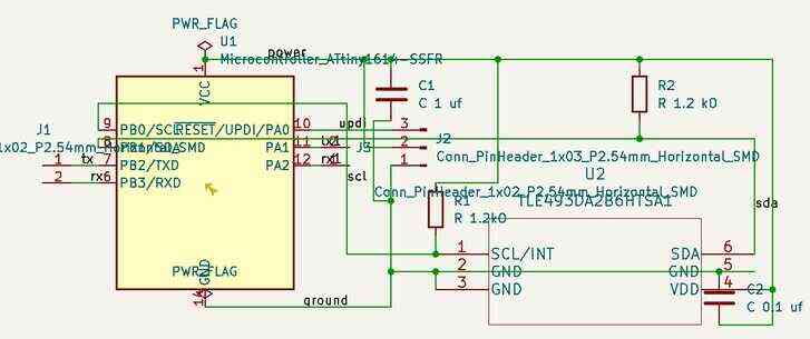
I then opened the schematic editor and made the following schematic with everything sharing a common ground (I connected the 3 ground pins of the sensor since there are 3 sensors inside of it for each axis, so I wanted to make sure they were sharing a common ground) as well as the sda and scl pins of the sensor going to those of the chip. The sensor can directly draw power from the chip since I will be using a 3.3V power source.
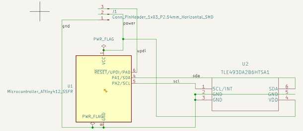
Then, I realized that I needed tx and rx pins to communicate with the serial monitor to display the data, so I added header pins for that.
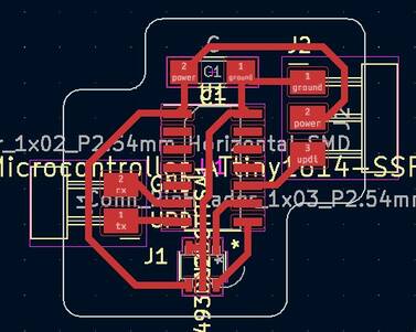
I then brought it into the pcb editor like so.

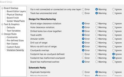
When I ran the electrical rules checker, however, I recieved the following errors of malformed courtyards.

Since I was not going to be using a courtyard, this was not a problem, and it most likely just did not like that the courtyard was not a rectangle, so I changed the settings for the ERC under file > board setup to ignore the courtyard errors as well as the silkscreen warnings since I wasn’t using a silkscreen either.
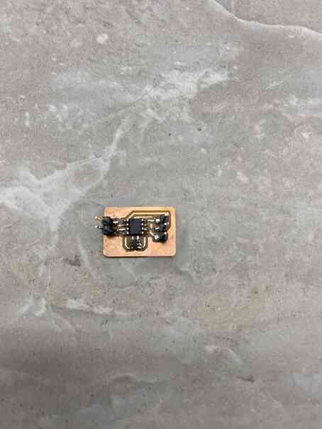
I then exported the gerbers, milled the board, and soldered the components on.
Code Attiny412 (failed)
When it came to the code, however, I wanted to use the arduino wire library for i2c, but I needed to find the slave address of the sensor, but I couldn’t find it on the datasheet or any other place I looked, so my instructor Dr. Harris recommended that I use the TLE493D arduino library, but that could not compile for the 412 chip, so I had to switch to a 1614.
PCB Design Attiny1614
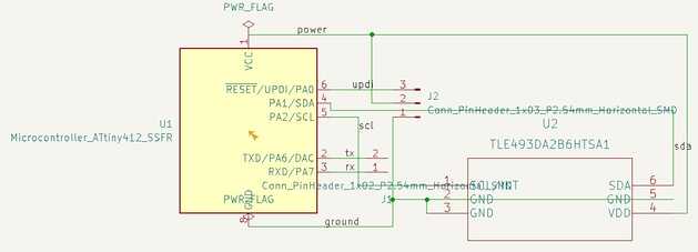
All I really had to do was replace the 412 with a 1614, so I did so in both the schematic and the pcd. I also decided to add a capacitor to stabilize the current.

I then milled and soldered the components on.

Code Attiny1614
I started with the following code:
#include <Tle493d.h>

Tle493d sensor = Tle493d();

void setup() {
  // put your setup code here, to run once:
  delay(10000); //delays a bit to give time to replug stuff
  Serial.begin(9600);
  sensor.begin();
  sensor.enableTemp();
}

void loop() {
  // put your main code here, to run repeatedly:
  sensor.updateData();
  Serial.print(sensor.getX());
  Serial.print(' ');
  Serial.print(sensor.getY());
  Serial.print(' ');
  Serial.println(sensor.getZ());
  delay(1000);
}
After uploading the code, I unbridged rx and tx on the programmer and connected the rx and tx from my board to it, but there was no serial ouput, so after consulting Dr. Harris and my classmate Aaron, I realized that I needed to change the code on my programmer to match the baud rate of the board and change another serial argument. For serial communication after uploading the code to the board, I uploaded the following code to the programmer and rewired everything back together.
void setup() {

   SerialUSB.begin(0);
   //Serial1.begin(57600, SERIAL_8E2); //Adjust baud rate and use SERIAL_8N1 for regular serial port usage
   Serial1.begin(9600, SERIAL_8N1);
  /*Trigger the reset line for the UART.
 This is supposed to trigger the target board's reset as if it is the RTS line. I couldn't figure out the SERCOM setting for
this in the SAMD11C datasheet*/
  pinMode(5, OUTPUT);
  digitalWrite(5, LOW);
  delay (100);
  digitalWrite(5, HIGH);
}

void loop() {
   if (SerialUSB.available()) {
      Serial1.write((char) SerialUSB.read()); //Send stuff from Serial port to USB
   }
   if (Serial1.available()) {
      SerialUSB.write((char) Serial1.read()); //Send stuff from USB to serial port
   }
} //end loop
It gave serial ouput, but it was not changing in response to the magnet.
I then thought it was possible that the magnet was too weak, so I tried a powerful magnet, but that still didn’t work.
In addition, the strong magnet also wiped the 1614 chip as I discovered when trying to upload new code, so I had to mill another board.
Since i2c requires pullup resistors, I reasoned that it is possible that the library does not enable the pullup resistors internal to the board, so I added some lines to do that with baremetal.
#include <Tle493d.h>

Tle493d sensor = Tle493d();

void setup() {
  // put your setup code here, to run once:
  delay(10000); //delays a bit to give time to replug stuff
  Serial.begin(9600);
  PORTB.PIN0CTRL |= 1 << 3;
  PORTB.PIN1CTRL |= 1 << 3;
  sensor.begin();
  sensor.enableTemp();
}

void loop() {
  // put your main code here, to run repeatedly:
  sensor.updateData();
  Serial.print(sensor.getX());
  Serial.print(' ');
  Serial.print(sensor.getY());
  Serial.print(' ');
  Serial.println(sensor.getZ());
  delay(1000);
}
This, however, still had the same problem, so I looked at the library more closely and found that it had a separate header specifically for the TLE493DA2B6, so I changed the code to use that instead.
#include <Tle493d_a2b6.h>

Tle493d_a2b6 sensor = Tle493d_a2b6();

void setup() {
  // put your setup code here, to run once:
  delay(10000); //delays a bit to give time to replug stuff
  Serial.begin(9600);
  PORTB.PIN0CTRL |= 1 << 3;
  PORTB.PIN1CTRL |= 1 << 3;
  sensor.begin();
  sensor.enableTemp();
}

void loop() {
  // put your main code here, to run repeatedly:
  sensor.updateData();
  Serial.print(sensor.getX());
  Serial.print(' ');
  Serial.print(sensor.getY());
  Serial.print(' ');
  Serial.println(sensor.getZ());
  delay(1000);
}
This again still had the same problem, and I could not think of what could be wrong, so having not learned my lesson from the last board, I tried a slightly stronger magnet, no where near as strong as the one that had wiped the last board however (I at least had some sense). This did not work and ended up wiping the 1614 on this board as well.
After taking a break and a long think, I thought of 2 possible problems: either the internal pullup resistors could not fulfill the needs of i2c or it was an issue with the library.
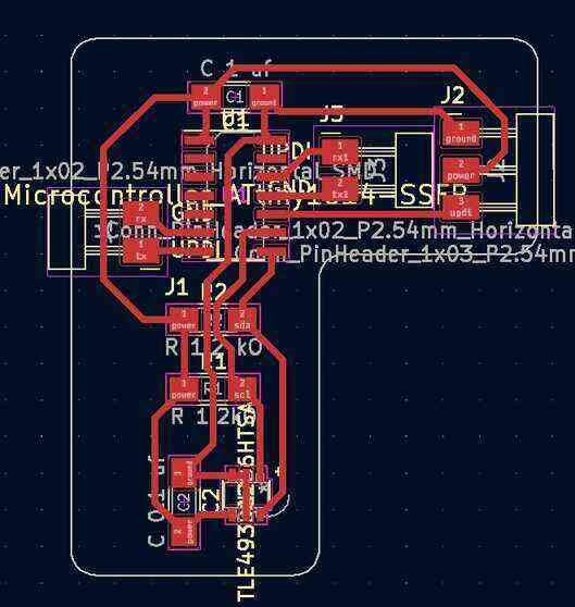
To solve the first problem, I made a new board with physical pullup resistors that would be 1.2 kohms upon finding that value as the optimal resistance on the datasheet. I also found on it that a 0.1 uf capacitor was needed, so I added that too. Additionally, with the advice of fab academy graduate Graham Smith, I moved the sensor away from the 1614 to prevent the magnet from wiping the 1614.
I then milled the board, and because some of the traces were very close together, I checked if they were connected with a multimeter set to the continuity feature, and they did not connect.
I then uploaded the code that I had been using, this time making sure to disable the internal pullup resistors, but it still did not work and had the same problem. I then concluded that it must be a problem with the library, so I switched back to my initial plan of using the arduino wire library and referenced Dr. Gershenfeld’s code. I made some changes such as changing the baud rate of the serial communication to match with what I had been using at 9600, and instead of storing the data input in 6 separate variables, I used an array and iterated through it to send to the serial monitor.
Then to process it into the actual x y z readings, I referenced Dr. Gershenfeld’s code that displays the readings upon recieving the data through serial specifically the following section:
v0 = ord(ser.read())
v1 = ord(ser.read())
v2 = ord(ser.read())
v3 = ord(ser.read())
v4 = ord(ser.read())
v5 = ord(ser.read())
x = (v0 << 4)+((v4 & 0xF0) >> 4)
y = (v1 << 4)+(v4 & 0x0F)
z = (v2 << 4)+(v5 & 0x0F)
if (x > 2047):
    x = x-4096
if (y > 2047):
    y = y-4096
if (z > 2047):
    z = z-4096
I consulted my teacher, Mr. Durrett, and fab academy graduate, Teddy Warner, to better understand how the data is being processed. I saw that for the x reading, it was putting together bits from disconnected bytes, and Mr. Durrett helped me realize that this was because the sensor was sending 12 bit integers, so the first 4 bytes were the first 8 bits of each of the 4 x, y, z, and temperature readings, and the last 2 bytes contained the last 4 bits of each of those readings. Upon seeing the subtraction after reading and putting together the readings, Teddy thought it could have something to do with 2’s complement and recommended that I watch this video to learn more. After this, I realized that it was indeed 2’s complement, and since the sign bit of the 12 bit integer, when coming in as a higher bit integer (32 in this case because of python while with arduino, which I am using, it would be 16), would not be in the sign bit position anymore, so it would have to be moved over. The checking of if the reading is greater than 2047 checks if there is a sign bit, and the subtracting of 4096 moves the number down to what it should be.
I ended up with the following code, which worked.
#include <Wire.h>

#define address 0x35

void setup() {
   //
   // start serial and I2C
   //
   delay(10000);
   Serial.begin(9600);
   Wire.begin();
   Wire.setClock(400000);
   //
   // reset TLE493D
   //
   Wire.beginTransmission(address);
   Wire.write(0xFF);
   Wire.endTransmission();
   Wire.beginTransmission(address);
   Wire.write(0xFF);
   Wire.endTransmission();
   Wire.beginTransmission(address);
   Wire.write(0x00);
   Wire.endTransmission();
   Wire.beginTransmission(address);
   Wire.write(0x00);
   Wire.endTransmission();
   delayMicroseconds(50);
   //
   // configure TLE493D
   //
   Wire.beginTransmission(address);
   Wire.write(0x10);
   Wire.write(0x28);
      // config register 0x10
      // ADC trigger on read after register 0x05
      // short-range sensitivity
   Wire.write(0x15);
      // mode register 0x11
      // 1-byte read protocol
      // interrupt disabled
      // master controlled mode
   Wire.endTransmission();
   }

void loop() {
   uint8_t data[6];
   int transformedData1[3];

   //
   // read data
   //
   Wire.requestFrom(address,6);
   for (int i = 0; i < 6; ++i) {
    data[i] = Wire.read();
   }

   transformedData1[0] = (data[0] << 4)+((data[4] & 0xF0) >> 4);
   transformedData1[1] = (data[1] << 4)+(data[4] & 0x0F);
   transformedData1[2] = (data[2] << 4)+(data[5] & 0x0F);

   /*for (int i = 0; i < 6; ++i) {
    Serial.print(data[i]);
    Serial.print(' ');
   }
   Serial.print('\n');*/
   for (int i = 0; i < 3; ++i) {
    if (transformedData1[i] > 2047) transformedData1[i] -= 4096;
    Serial.print(transformedData1[i]);
    Serial.print(' ');
   }
   Serial.print('\n');
   delay(500);
}
Group work
Our group work for this week can be found here.
I worked with Aarush on seeing the signals from my board on SDA. I contributed both my board and interpreting the results from the oscilloscope.