10. Molding and casting
This week I learned how to design molds with fusion and mill them out and cast them.
All design files used can be found here
Rook Mold (failed)
Design 1 (failed)
To get some work done for my final project, I decided to try to make a rook piece.
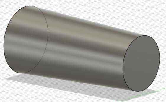
I started with 2 circles for the top and bottom.

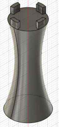
To get the general shape of the body, I lofted them together.
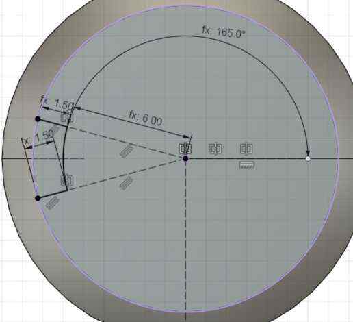
I then made the tabs on the top. One construction line goes to one point on the arc and is mirrored across the horizontal line to get the other point. The arc is then connected to the outer circle with 2 lines.
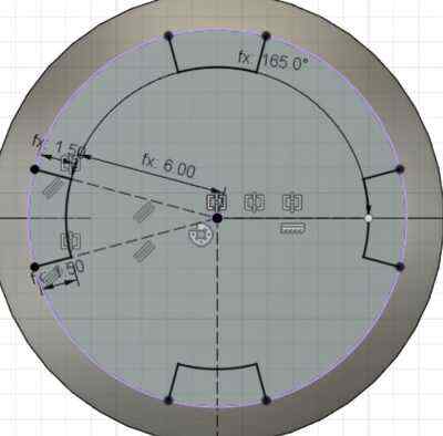
To get the other tabs, I used the circular pattern tool.
I then extruded the tabs up.

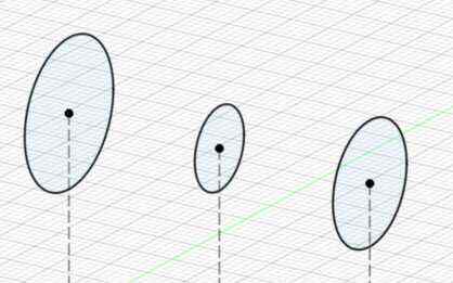
After looking at the shape, I was dissatisfied, so I went back in the fusion timeline and added a smaller middle circle to the loft.
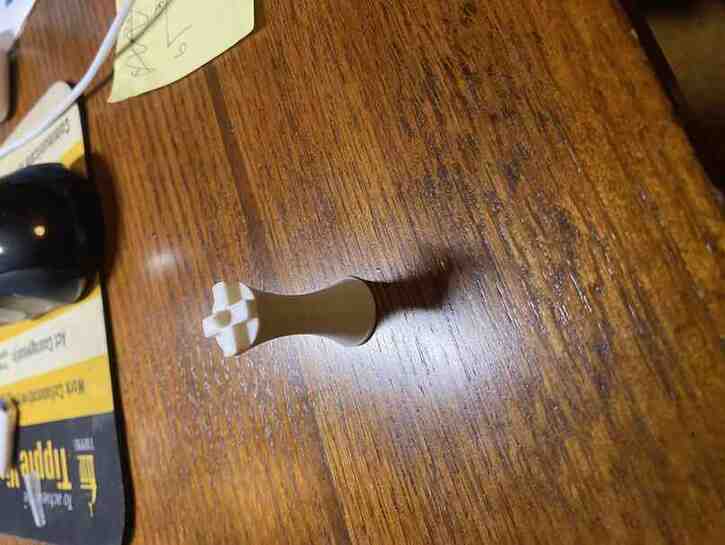
To get a better idea of what it would look like, I did a 3d print model.

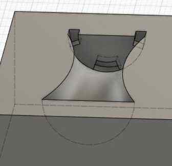
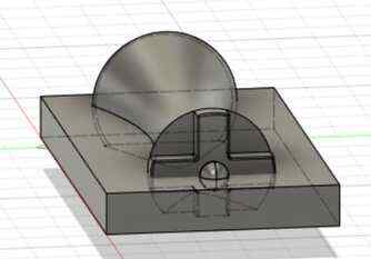
I also made a box around it and combined it using the piece as a cut into the box, but after this, I realized that it wasn’t possible to be milled since the bottom tab had an overhang over it.
Design 2
So I redesigned it by having the tabs go all the way across in a cross shape and adding a sphere at the top using the sphere tool.
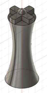
I also did a 3d print model of this design too.
I also realized that since I wanted to use a rigid material, I needed to have the machine mill the positive surface shape so that I could pour soft material in it to construct the mold since pouring rigid material into a rigid mold would make it so that it could not be taken out. I referenced Rico Kanthatham’s documentation for this.
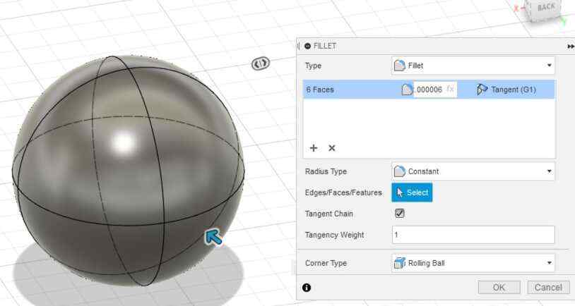
I then wanted to change some parameters, but since the point specifying the center of the sphere could not be defined parametrically, and it could not be constrained to a parametrically defined point, I had to change it to a cube filletted to be a sphere. I couldn’t make the fillet exactly the radius of the sphere, so I made it as close as possible.
I then made a box around the piece.
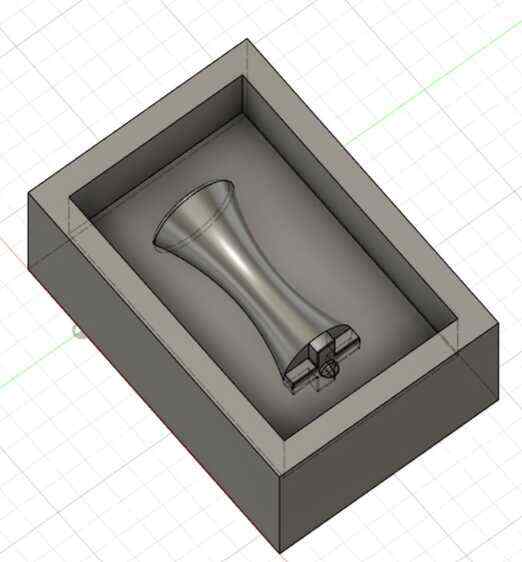
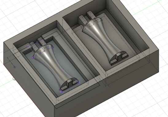
When I tried to combine the piece and the box, I couln’t because of the sphere made from the cube, so I deleted it and joined them. I also duplicated it and added a lip on the bottom as a register to hold the 2 mold pieces in place.

To finish, I added a vent so that I could pour material in and allow air to escape. The vent interfered with the extrude of the lip for the register in between the 2 rectangles, but it wouldn’t matter since that region would be flush with each other, and the register along the rest of the piece would still hold it together.
Fusion CAM
I then opened the manufacture workspace in fusion and followed this workflow for using fusion with the bantam tools othermill.
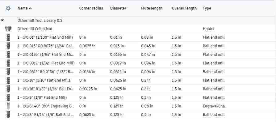
I first downloaded the bantam tools library, extracted it, and added it to fusion’s tools as a local library.
In the setup under the first setup tab, I defined the axes, defined the origin, selected the body to be milled out, and selected the machine displayed below.

In the stock tab, I set the mode to fixed sized box and entered my stock dimensions and had the piece sit flush with the top of the top face of the material and with some offset from the left and front faces. I also set it to round to the nearest 0.
For the toolpath, I selected the 3d adaptive clearing toolpath. In the tool tab, I selected the 1/8 inch ball end mill and made sure coolant was disabled. In the geometry tab, I unchecked stock contours and rest machining. In the passes tab, I set the optimal load and maximum roughing stepdown to at most half the diameter of the bit, in this case 1.5mm, and I kept the default value for stock to leave.
I then made another toolpath with the same configurations as above, but I unchecked stock to leave since this was the finishing pass.
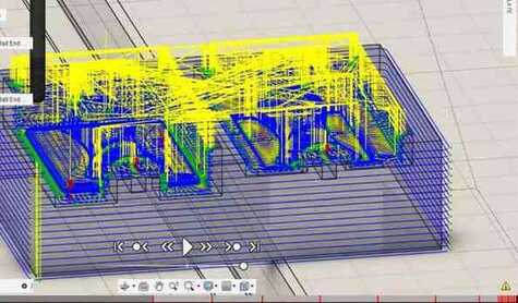
After generating these 2 toolpaths, I ran a simulation of them, but I got many collision with stock errors.
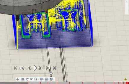
I tried to make the design smaller, but the smallest I was willing to make it still had collisions.
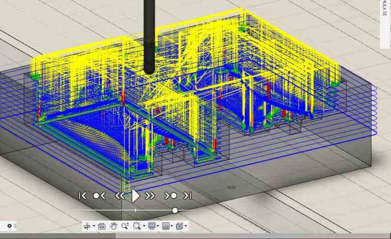
I then thought that the thing that was causing the collisions was the fact that it would mill the outline of the box around everything down to the bottom, which was actually lower than the lowest feature I needed it to mill, so I went into the heights for both toolpaths and changed the bottom height offset to 10mm, and that still did not work; there were less collisions, but there were still some remaining. These collisions, however, were just rapid collisions with the stock by the bit and not the collet hitting the material, so my teacher, Mr. Budzichowski, recommended that I decrease the lead in speed, and that worked.
I then went to mill, but my instructor, Dr. Taylor, pointed out a few things with my files. The 1/8 inch ball end mill that I was using for the roughing pass was really more of a finishing tool and so he recommended a flat end mill, and the finishing pass should use a smaller, more precise bit like a 1/16 inch ball end or a 1/8 inch chamfer bit. I also realized that I was missing a small lip at the top of each part to better remove the pieces, something I saw on Adrian Torres’s site. Dr. Taylor also told me to look at the different finishing passes that fusion had and look at the examples to decide which one was best.
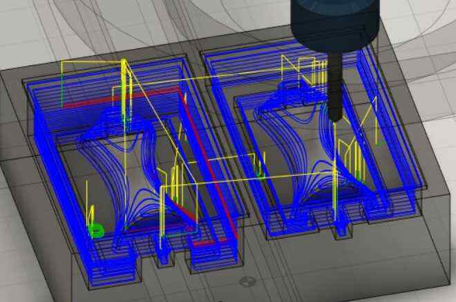
Upon taking Dr. Taylor’s suggestions, I realized that 3d adaptive clearing was a roughing pass, so I switched to passes actually designed to be finishing passes for my finishing pass. I switched the tool in my roughing pass to the 1/8 inch flat end mill. I also decided to use different finishing passes since I had different geometries in difference parts of my design that different passes were optimal for.
For my first finishing pass, I used the horizontal pass to smooth out all my horizontal flat faces.

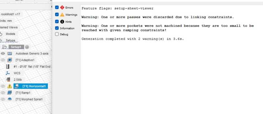
It gave the warning below, but it would not impact the cut very much since it was just warnings about not being able to cut some parts, which the later finishing passes would pick up.
My second finishing pass was the ramp, which is good for smoothing out any walls. I used it for all of the lips and the spaces around the vents. It also cut a bit of the main piece body since it was selected when I selected the inner lip.
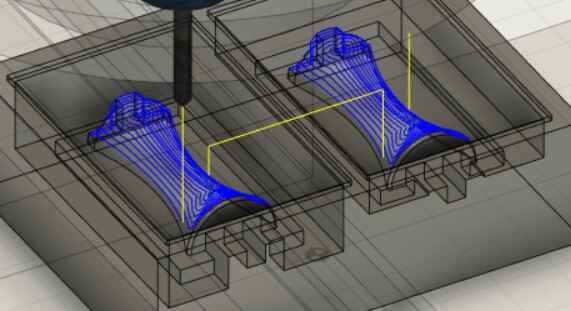
My last finishing pass was the morphed spiral, which is good for organic curves, so I used it for the main piece body.
Postprocessing, Milling, and Molding
To export the gcode, I selected each toolpath and under the actions tab hit post process. I changed the machine to the othermill, the filename, and the folder it would save to and left everything else on the default and exported it, but I received the following warning:

Together with my classmate, Aaron, and Mr. Budzichowski, we found a solution. Back in the setup under the post process tab, the WCS offset had to be changed to 1.
When I went to mill, however, I realized that the lab did not have the chamfer bit that I needed. I tried to switch to the 1/16 inch ball end mill, but the shaft would collide with the stock, so I could not mill this design
Cone Mold
After going through designing the rook and failing, I decided that it would still contribute to my final project since the file would still be useful for 3d printing the mold instead of milling it as required for this week’s assignment, so I decided to instead mill a cone mold since it is a simple shape that would not have such deep cuts.
Design
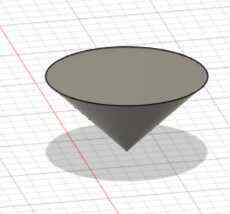
I started with a sketch of a triangle that would later be revolved to form the cone.
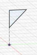
After rotating, it gives the following cone:
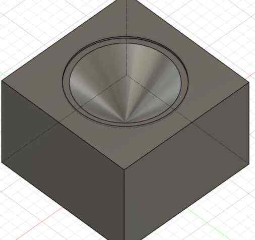
I then made a box around the cone and joined them with the cone as a cut.
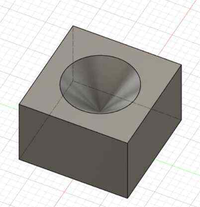
To make the cone easier to remove, I added a small lip on the edge.
CAM
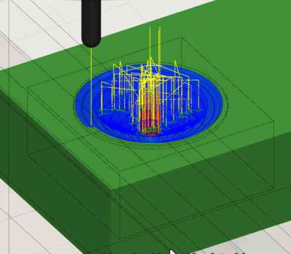
I went through the same process as described above with the CAM for the failed rook except with just a 3d adaptive clearing roughing pass and a spiral finishing pass, and in the simulation it worked.
I then post processed, and that went smoothly, and I milled, and that also went smoothly. There are some grooves despite the spiral finishing pass, but it is probably due to the fact that I used a 1/8 inch ball end which might have been too big for such a small thing, but the bits and machines were in high demand, and I couldn’t get access to some of the bits, or setting the stepover lower might have made it better too.

Pouring the Mold
I used mold star 20T and found from the datasheet that the ratio of the 2 parts by both weight and volume is 1:1.
When pouring the mold star 20T, I overestimated how much material I would need, but the extra could be cut off easily.
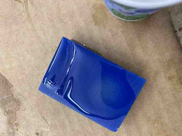
It turned out nicely like so:

After trimming some of the excess material, it turned out like below. I accidentally ripped into the cone a bit, but it still turned out fine.

Cone Mold 2
Since the finishing pass did not turn out too well since the stepover was too high, I went back and lowered the stepover and remilled and repoured the mold, and that turned out well with a smooth cone after the 3d adaptive roughing pass and the spiral finishing pass.

Group Site
Our group work for this week can be found here.
I worked on pouring task 8 and dragon skin for group A2 and observing the results. Task 8 turned out rigid while dragon skin turned out extremely flexible.