10. Molding and Casting
Week 10, back to the physical world…whew. Last week was hard, hopefully this week will be fun as we are back to the realm of the physical. My brain was on the verge of exploding last week as I tried to ramp up to a level of understanding on subjects that were foreign to me. Making things with my hands…I will hopefully not have struggle so much.
The Rattleback (shown to us by Neil) was very cool. It triggered a memory of something I saw on YouTube on the topic of 3D printing. After a bit of searching, I found it. This week, for the Molding and Casting assignment…I will look into “Solids of Constant Width” and a “Sphericon”
The Group Assignment page here
The Solid of Constant Width
It seems the circle is not the only “Constant Width” geometry…basically a shape whose top surface remains the same distance from the floor plane even if it rolls. Introducing the Reuleaux Triangle and the Messier Tetrahedron
Angus Deveson of Maker’s Muse explains both in these fantastic videos…here and here
The Simple Reuleaux Solid
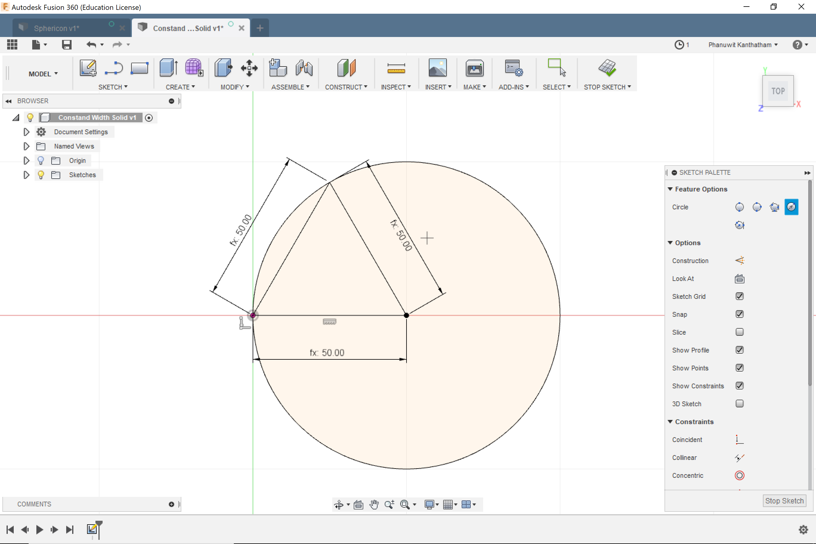
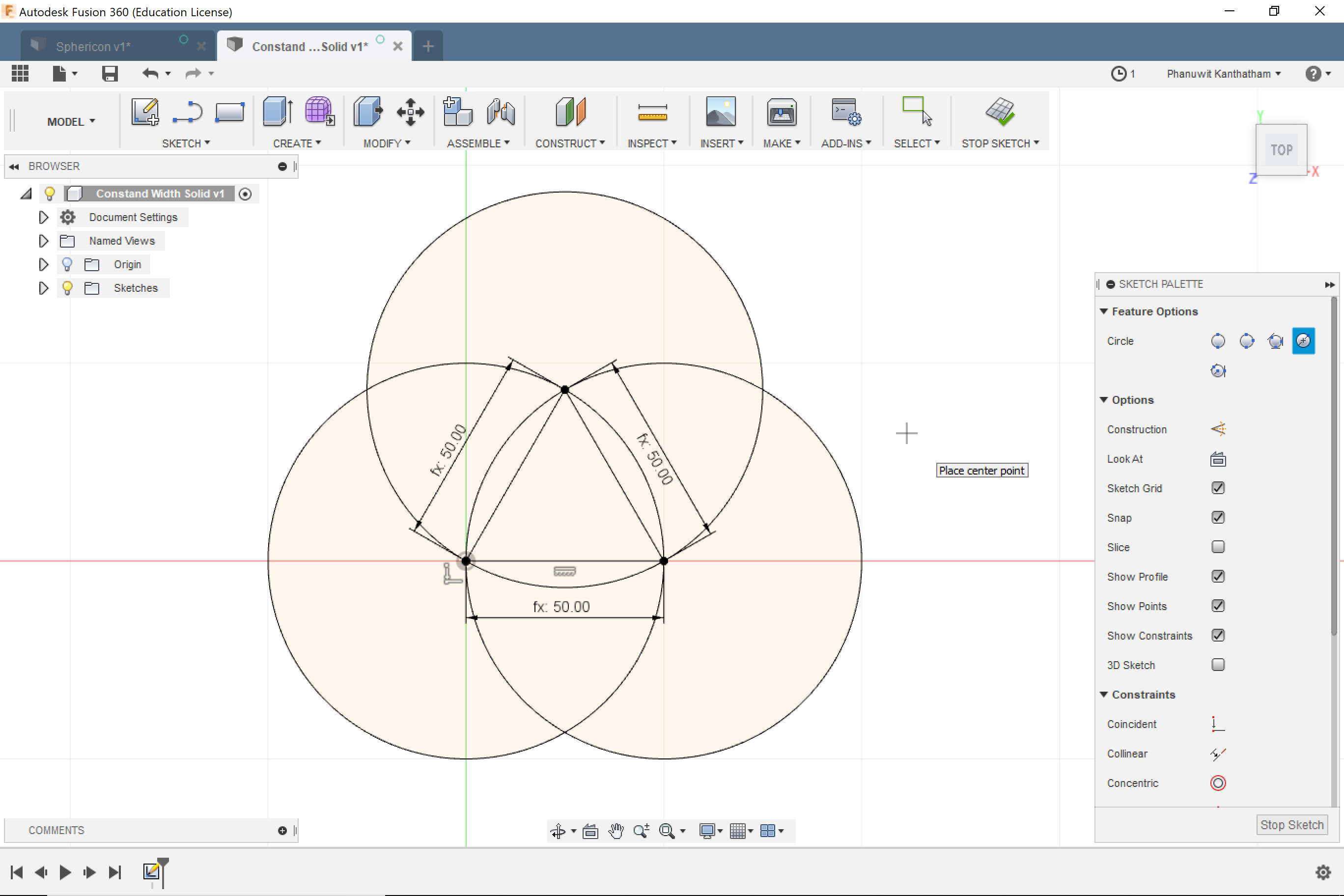
Start with an equilateral triangle (parametrically!), then 3 circles drawn with one vertice as the center and the other as the radius…
Then a whole lot of trim commands will result in a triangular shape composed of arcs…the Reuleaux triangle
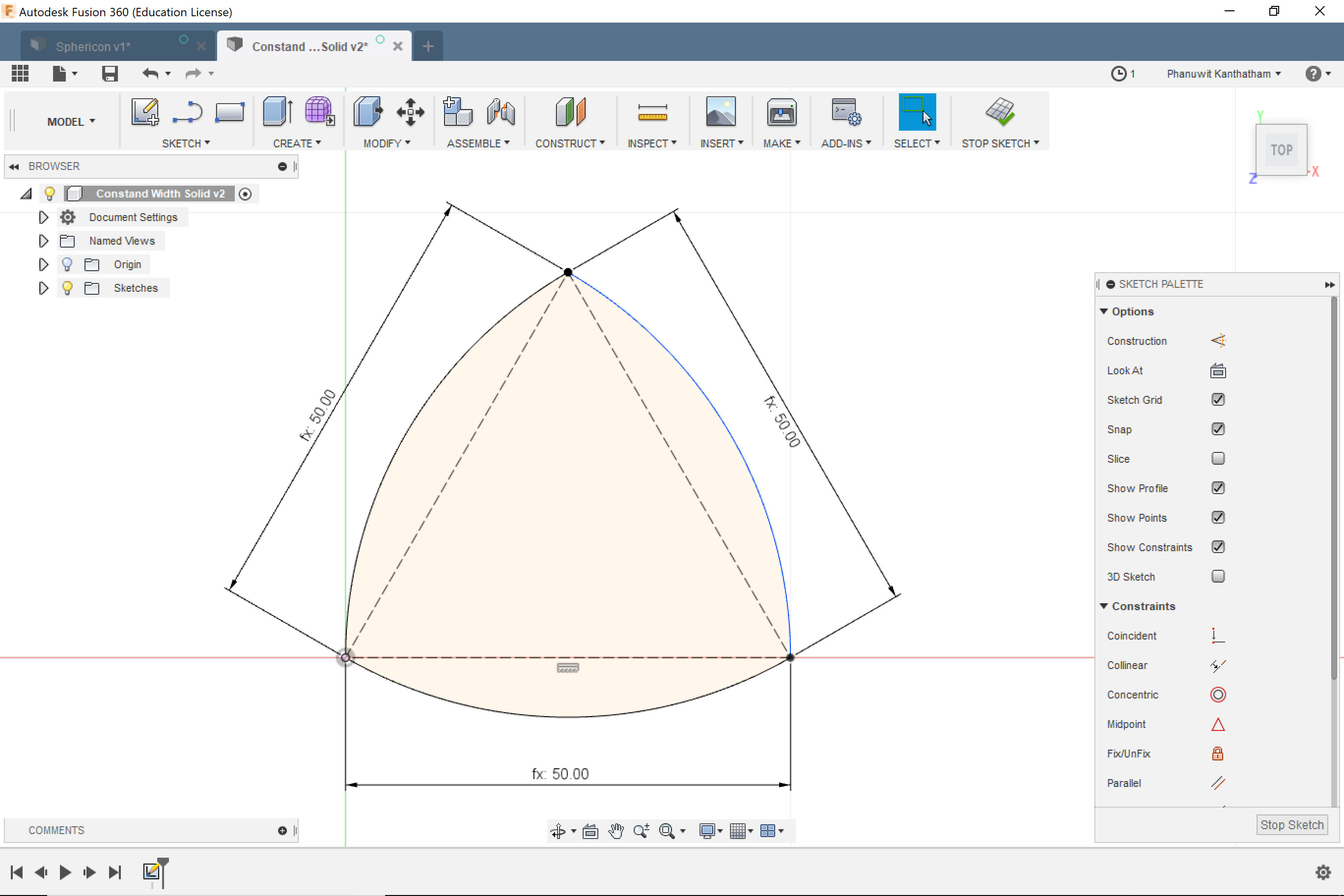
Revolve the triangle around its verticle axis…
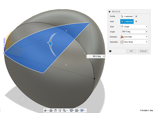
The Reuleaux Solid
The Messier Tetrahedron Solid
Create an equilateral pyramid (first time to use a complex mathematical equation in F360 to make the Z-axis verticle)…
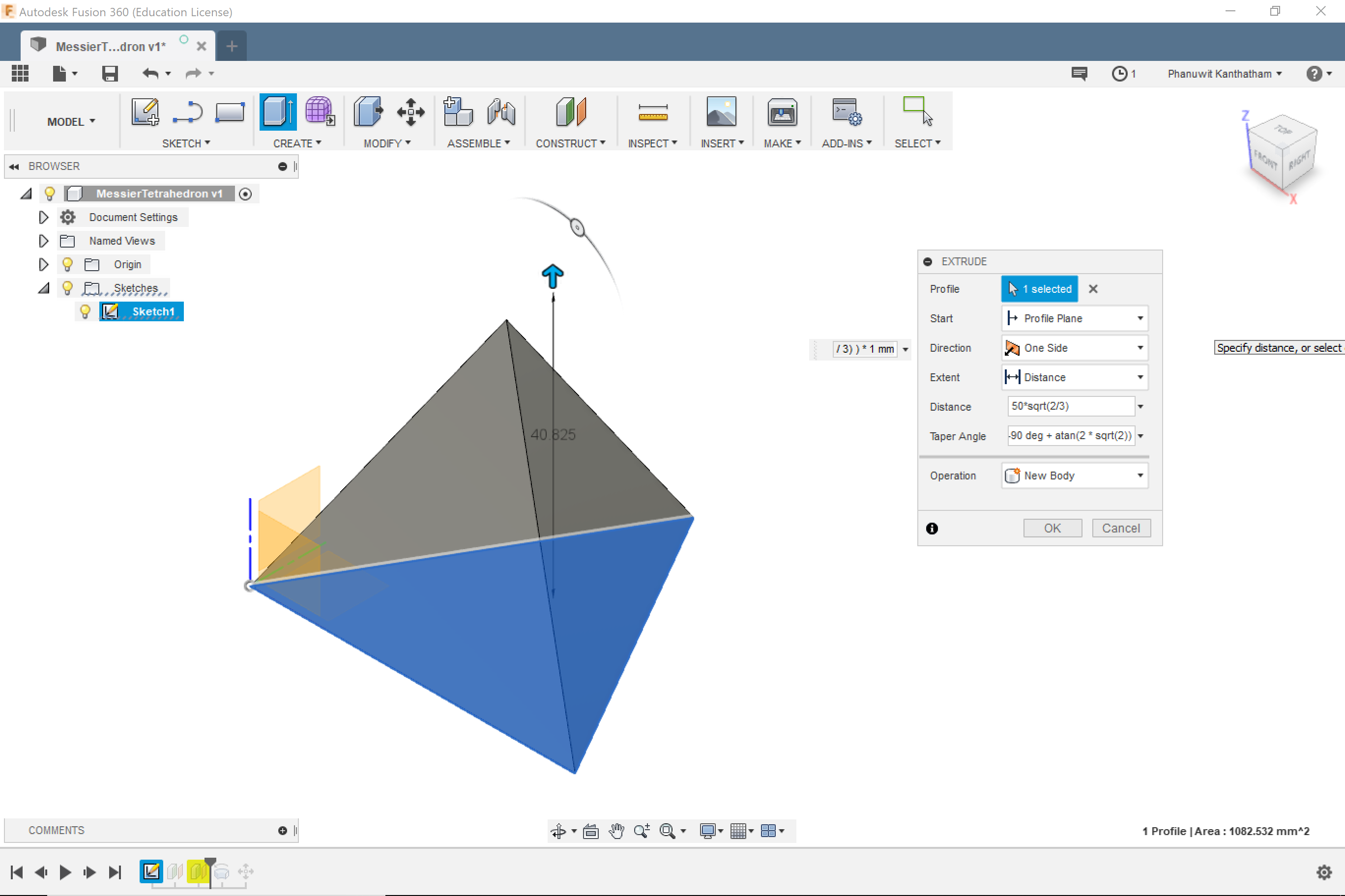
Place spheres (with the same radius characteristics as those of the Reuleaux) at each of the 4 vertices…
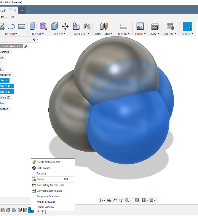
Trim commands to end up with…
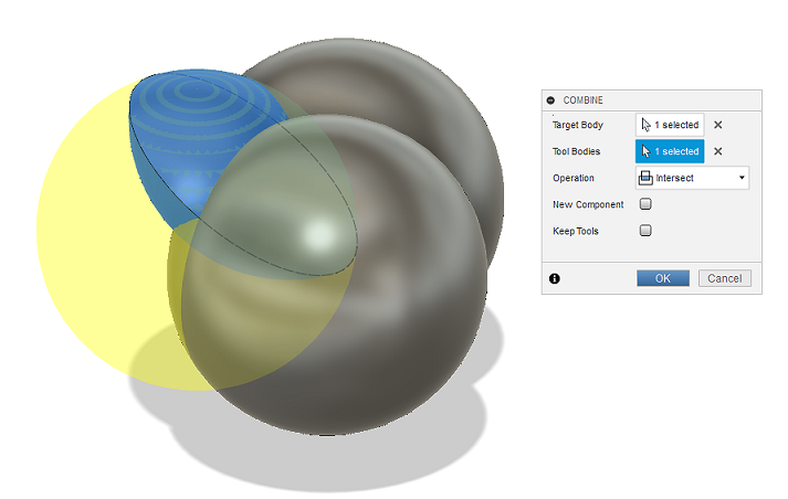

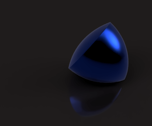
…The Messier Tetrahedron

The Sphericon
According to Wiki, David Hersh…Israeli toy and game inventor, came up with the Sphericon…”a device for generating a meandering motion.” Basically a Bi-cone split in half and one half rotated 90 degrees. A more in depth description of a ‘Sphericon’ is here
And another video from Angus Deveson, “Incredibly Satisfying Sphericons” here
Draw an Isoceles Triangle…
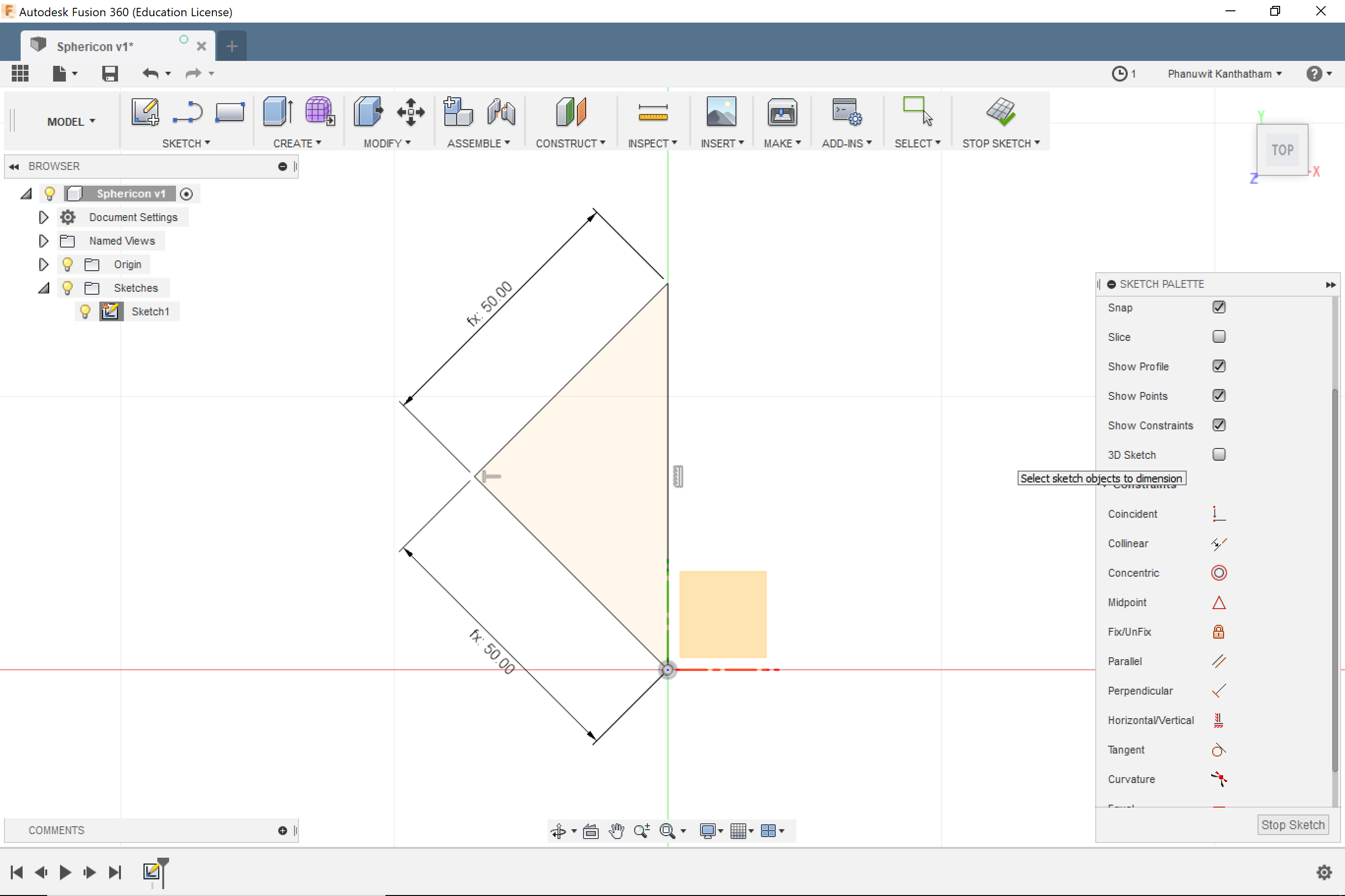
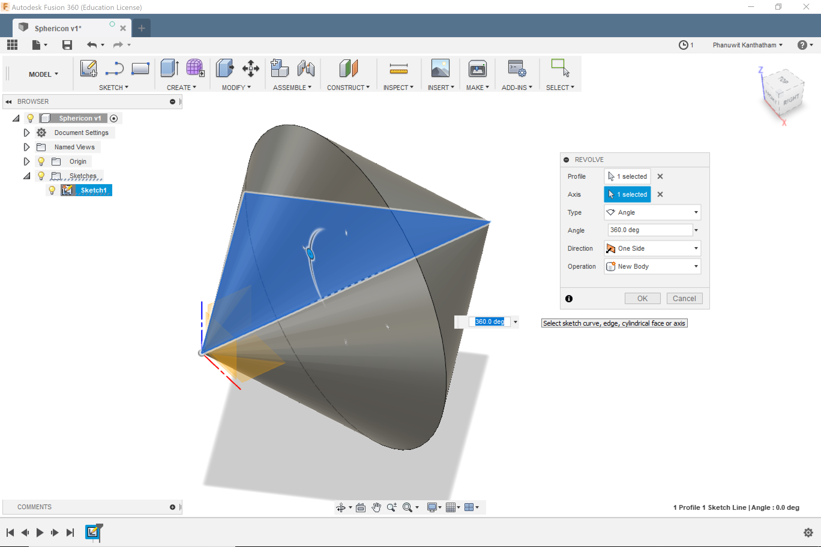
Revolve it around its long edge…
Split the Bi-cone along its vertical axis…and rotate one of the halves 90 degrees…
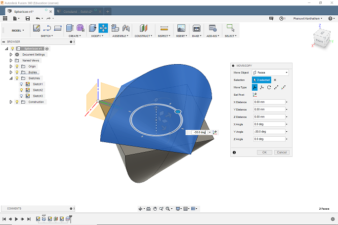
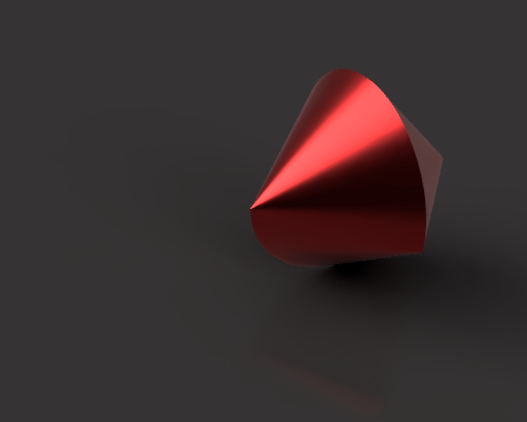
…The Sphericon
Making the Mold Models
Now comes what I perceived to be the hard part…making mold models for each of the geometric solids. Back to YouTube to learn to make molds. Found this video by Kevin Kennedy, “How to Create A Two-Part Mold in Fusion 360” here
Making 3D Models of molds
Following Kevin Kennedy’s tutorial, I created mold models for each of the 3 objects that I intended to cast. The process was pretty straight forward.
- Use the object to combine/cut a shape in an enclosing cubic representation of the mold
- Cut the resulting mold form in half, added 5mm overlapping, registration edges…the Reuleaux and Messier Tetrahedron splits nicely on vertical access…The Spherion more complicated
- Add ‘Fill’ and ‘Vent’ holes to allow for casting liquid to be poured in and air to escape in the process…figuring out the size and location of the holes took a bit of thought…deciding where the hole would scar the final object the least and a vent hold near the highest point where air is likely to get trapped.
The result for the Sphericon here…
Animations:
Reality Hits…
Seems like a pattern for FabLab sessions. Preparations are never enough.
3 object models made along with 3 mold models for each…ahead of the work session, but logistical constraints forced a change of plans…
- I needed to also model a “Mold of Mold”…the negative of the mold to cast the object (Soft Mold)…will be milled from hard wax (Hard Mold)
- The mold models I made so far did not account for the size of the actual mill stock…147mm x 88mm x 37mm…scaling reduction (~30%) will need to be done
- There is only 1 milling machine in the lab and each milling event is likely to last about 2 hours…milling 3 objects not gonna be possible
So…decided to reduce my scope and focus on one object…the Sphericon
After some effort, here is the resulting “Mold of Mold”…
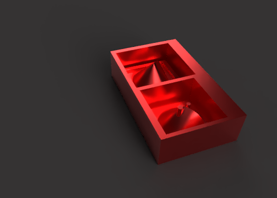
Next step…export as STL file…which will be converted to Gcode by the milling machine software in the next step
Note: I made an effort to utilize Parametric Modeling whenever possible. Having had to make quick adjustments during the work session to complete my assignment, I had to work quickly through modeling and abandon the rigor of Parametric Modeling. A combination of my still limited familiarity with F360, impetus to hurry…and poor definition of parameters made it tough to continue with PM when I had to work at less than leisurely pace. On the last point, it occurred to me that I need to be more thoughtful in defining my parameters…not have so many individual parameters, but many related individual parameters. Like the process that I used in the Laser cutter assignment week, there should be one or a small handful of base parameters (with geometric relationships)…and subsequent parameters should ve derivatives of these ‘Seed Parameters’. If the base parameter is ‘x’ in length, subsequent parameters should have a mathematical relationship to ‘x’, such as…x/2, 1 + (2 * x), x^3, etc. Doing this is the only sure way to be certain that parametric changes will properly propagate through a model…right?
Milling the Mold of molds
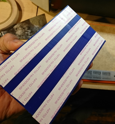
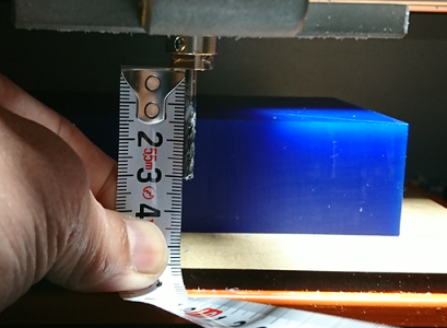
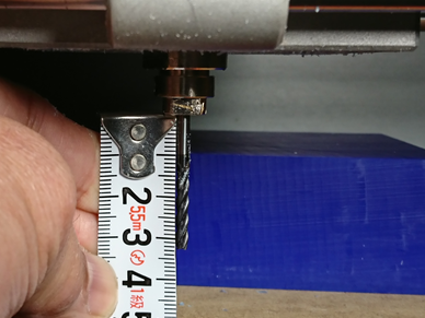
- Secure the mill-stock (Hard Wax) to the mill bed…using double-sided tape…to the mill tray surface.

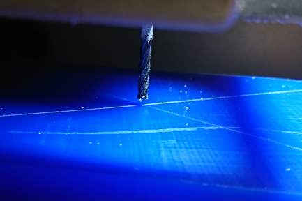
- (Before reinstalling the tray surface back into the Roland enclosure…) Score the top of the wax block with a scribe…from one diagonal corner to the other…to mark the center of the top surface.

- …this makes establishing the XYZ origin for the milling much…much easier. (Note that for this purpose, the center of the block…not a corner…is used as the zero origin point)
- Because the deepest point in my mold is 32mm, there is a risk that the milling assembly may crash into the sides of the model if the endmill bit’s shank is not lengthened a reasonable amount to limit this possibility. 30mm extension is lengthened to 33mm.
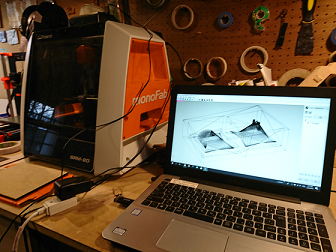
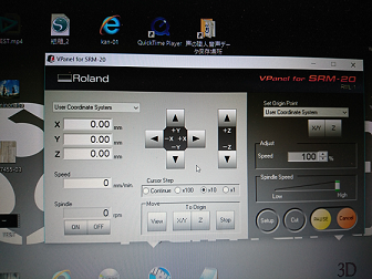
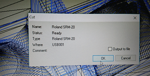
Modela Player 4
Using a new software to drive milling on the Roland SRM20 today, Modela Player 4. It has that Vcarve feel…functional but not so friendly. Thanks as always to Caterpillar sensei for his guidance…
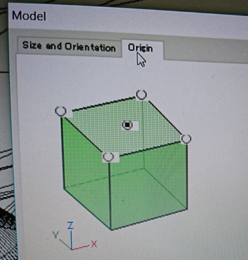
Head into the ‘Set’ menu
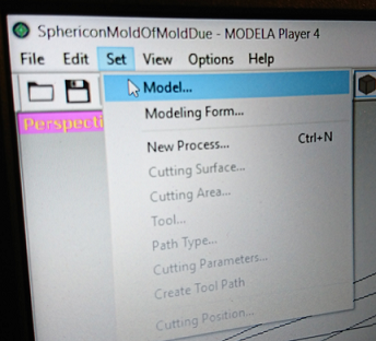
Establish the ‘Zero Origin’ as the center of the top surface of the hard wax ‘Mill Stock’
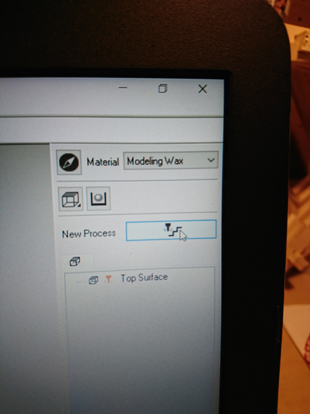
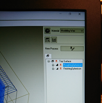
Head into ‘New Process’ to load up the mill path for the Sphericon Mould of Mold (I think this is where the STL is selected…need to confirm)
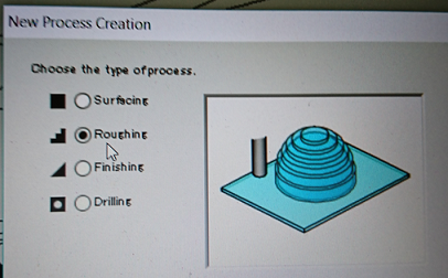
Choose ‘Roughing’ to define the ‘Rough Cut’ cut Path
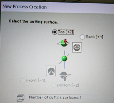
Choose the ‘Top’ surface as the starting ‘Cutting’ surface
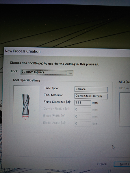
Define the endmill to be used…if the endmill being used is not in the selection list…it can be added.
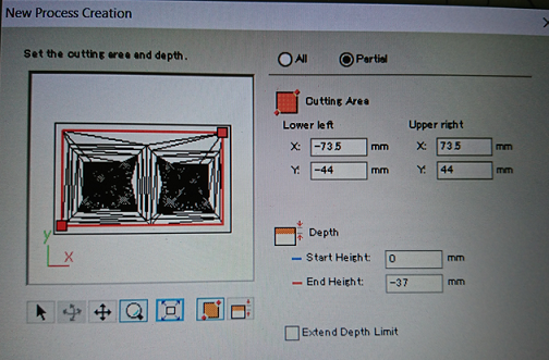
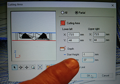
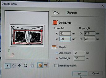
Define the area on the ‘Mill Stock’ for a cut path to be generated…by dragging the corners of the red box around (rather imprecise) or using the Pos/Neg X/Y numbers to make the adjustments (much more precise). The block image representation can be zoomed into. Also…define the starting cut depth here (we used zero, but I still wonder if -1mm couldn’t have been used). The ‘End Height’ is established at 37mm…the height of the ‘Mill Stock’
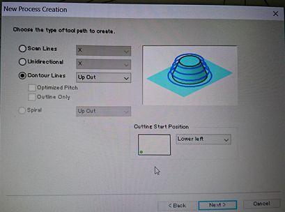
Define the ‘Roughing’ cut path as ‘Contour’ style
Define travel speed = 20mm/sec (‘XY Speed’), feed = 10mm/sec (‘Z Speed’), spindle speed = 7000, & ‘Cutting-in Amount’= 1.2mm and step offset = 0.2mm (‘Path Interval’) here. I followed recommended settings used by students from last year.

Name the cut path file and tell Modela to generate a cut path ‘Right Now’…press ‘Finish’ and wait
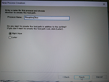
…for the ‘Roughing’ cut path to be generated. Which can be previewed for cut path errors.
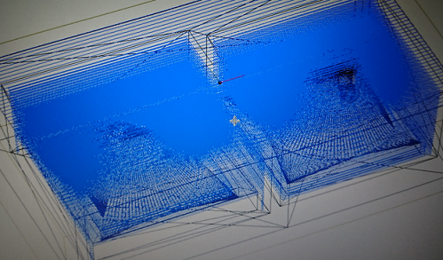
Repeat the 10 steps for generating the ‘Roughing’ cut for the ‘Finishing’ cut path…differences in settings vs ‘Roughing’ as follows…
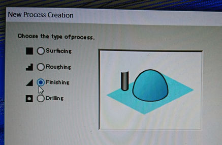
Choose ‘Finishing’
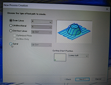
Choose ‘Scan Lines X’ (in retrospect, I think I might have chosen ‘Contour Lines’ for cuts in both X and Y directions to result in a smoother surface…will try next time)
Cutting parameters (Feeds & Speeds) for ‘Finishing’ was kept exactly the same as ‘Roughing’ (on the advice of instructors)

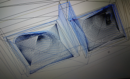
A ‘Finishing’ cut path was generated, but clearly shows scan lines in places that don’t really need finishing work.
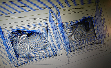
Back to ‘Cutting Area’ settings to adjust where and how cut paths should be generated…to reduce milling time.
The resulting estimated milling time for the mold of mold is approximately 2hrs…wow. Long.
With the paths generated to reasonable satisfaction…it’s time to mill. Get pass a few of the last warning dialogue boxes…
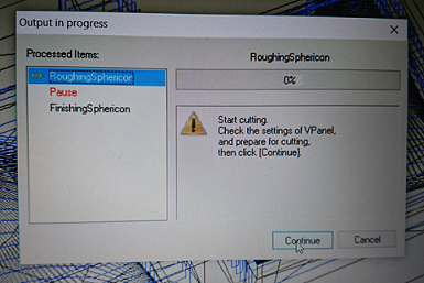
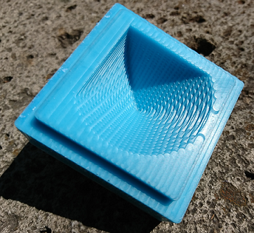
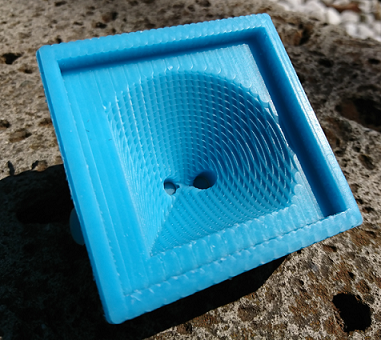
…and 1hr 43 mins later, the ‘Roughing’ was completed. Respectable results…
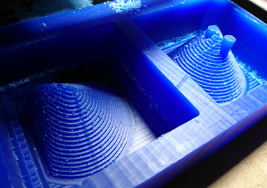
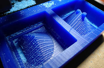
…another 10mins, and the ‘Finishing’ cut is completed…to disappointing results…not smooth as expected, but no more lab time so I choose to accept it to complete the molding and casting aspects of the weekly assignment. I tell myself that smooth is overrated…and moved on.
Casting the Mold of Molds
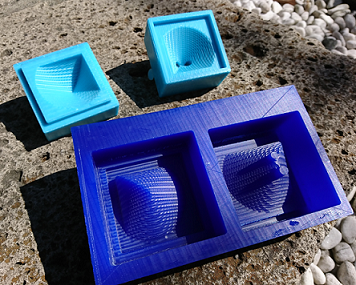
Used the Moldstar 16 Fast to make the soft mold. A 2-part mixture…I guesstimated 200ml (100ml each of Parts A & B) as the adequate amount to fill both boxes of my mold. Mixing took some time but not hard to do. Pouring was easy. Ended up using just 70% of the mixture. Instructors broke out a sander…using it to vibrate the table on which the mold sat…to vibrate out any trapped bubbles (loved the ugly hack). About 5mins of that and the material was already hardening. I left the mold to cure overnight.
Arrived the next morning to find the mold is dry and rubbery. Took a bit of effort to peel it out of the mold, but the mold ‘rubber’ is tough and dealt with my manhandling without issue.
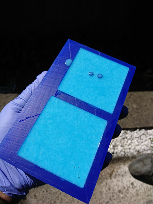
The molds looked…great. Fantastic finish with great detail resolution (I am in love with MoldStar 16)
The cast material covering the Vent & Fill holes removed easily…though their closeness makes the rubber in between vulnerable to breakage. I will have to rethink how and where I put these holes in future models.

Making Casts of Objects from Flexible Molds
With the molds in good shape, it’s time to cast the final object. While setting up to make the cast, I was concerned about how to fill the mold with casting material through the 1/8” fill hole. Not wanting to make a complete mess, I made a feed funnel out of a plastic file folder…
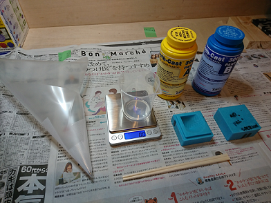

Time for casting…
- Mixed 100ml of Smooth Cast 300 (50ml each of Parts A & B)…used chopsticks under the canister lip to control the pour stream
- Made an initial pour into the bottom mold cavity to about 95% full…then put the top mold on and filled the rest of the mold with the hand-made funnel (worked like a charm!!!). Ended up using only about 50ml of the mix
- Smooth Cast 300 pours like water and cures super fast…hardening in just a few minutes and achieving complete cure in 10mins. It gets really warm as the two chemicals react to one another.
The casting process proved to be the easiest part of the entire weekly work session.
The Results
The Sphericon turned out beautifully, with only a tiny bit of flashing to clean off with an Xacto knife. The mold worked great with registration and detail coming out nicely. The Smooth Cast 300 was trouble-free to remove from the mold and looks and feels great.
Here is the Sphericon after a tiny bit of post-processing, in meandering action…
For kicks and giggles, I made a second cast, this time adding some green pigment with the hope of a marbled finish. Here is how it turned out…
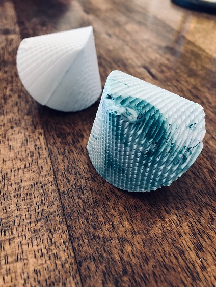
On close inspection, one can see lots and lots of tiny bubbles on the object surface…hidden by the unintended surface texture of the cast Sphericons.
Learning Outcome Summary:
- The mold process was more involved that I had imagined…a mold of mold needed to be made which I didn’t anticipate
- Milling takes a long time
- The mill path software is really not user friendly…should try to get Fusion 360 to run the milling
- I failed to get a smooth finish for my object…but achieved an ‘Accidental Beauty’ that I quite like (which incidentally hid tiny bubble flaws)
Feed & Speed should have been adjusted for the ‘Finishing’ cut…slowing down the XY speed from 20mm/sec down to as low as 5mm/sec and the Cut Path Interval reduced to 0.5mm (recommended by instructors in other labs during Asia Review).
- Working with the chems to make the mold and cast was relatively easy…compared to the other processes
- There is a lot of waste generated though…which made me ask myself if there is a less environmentally polluting way to do this…
- The cast itself was surprisingly fast…and the results above my expectations
- …another skill added to the tool chest, I am really enjoying the Fab Academy experience.
Can’t wait till next week!!
STL and F360 Model Files of This Week’s Objects
Sphericon STL file here and Fusion360 file here
Sphericon Mold of Mold STL file here and Fusion360 file here