15. Mechanical Design
The Kura CoreXY Brush Painting Machine
Group Assignment page here
Machine Design Concept
The Kamakura lab has decided to build a Brush Painting Machine (BPM). But rather than utilize off-the-shelf parts sourced from elsewhere, we wanted to see if we could build a ‘Sloppy’ machine utilizing locally available or lab fabricated, unconventional machine building materials…with the goal to create artistically imprecise ink brush paintings (Sumi-e).
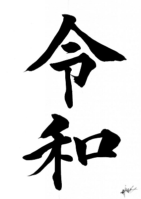
The “Kura CoreXY BPM” will be constructed with a combination of digital (New School) and analog (Old School) fabrication techniques. As our machine’s function is to paint ink brush characters where expressive brush strokes and ‘beautiful accidents’ are valued…precision is not a priority.
To this end…
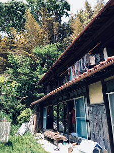
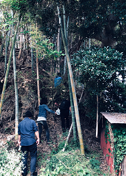
- We intend to use locally harvested bamboo to make most of the machine frame and part of the mechanical system. The bamboo was harvested for free from Takenoko-an, a guest house in the town of Kamakura with a bamboo grove that needed pruning (we trade labor for material). As a key material for the machine, we are aware of the imperfections and dimensional variances that are characteristic to bamboo. We understand that this will certainly result in machine ‘sloppiness’ and likely some unpredictability in the mechanical movement. We intend to factor these characteristics into the machine design, making good use of it to generate artistic brush movements and a unique drawing every time.
-
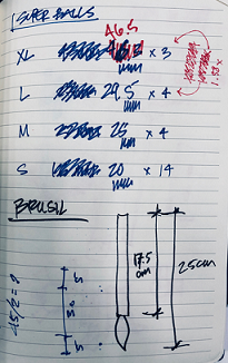
The other parts of the machine will be designed and fabricated in the lab (3D printing, mostly) or purchased from local shops…superballs from local toy store; bamboo brush, ink, paper and twine from the local stationary store…to support the mom-and-pop stores of the local community.
-
The Stepper Motor, Rubber Drive Belt and , Toothed Spidles will hopefully be the only off-the-shelf machine parts utilized for the Kura CoreXY BPM.
Member Tasks
The agreed upon division of labor is such that one student colleague will be responsible for Electronics and Machine Programming (character painting movement control and gcode generation), and another for the End Effector (Brush actuation mechanism and programming). My job is to design, fabricate and build the Physical Machine and Core XY Mechanical systems.
Mechanical Design
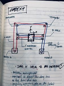
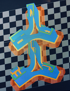
I began the process of the machine design by trying to understand the CoreXY concept…how movement is effected and the mechanical features needed to make it work. My understanding is that it is a belt driven system managed by the spindle rotation of two stepper motors that either rotate in the same direction, opposite direction or individually.
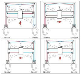 image by Bahaa Shaquor
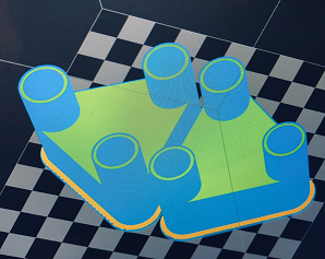
Required CoreXY mechanism parts include:
- 2x Stepper motors
- 10x Geared Spidles (including 2x attached to the Stepper Motors)
- 2x 6mm wide x 1000mm long, Toothed Rubber Drive Belt
- 1x End Effector Plate/Belt Capture
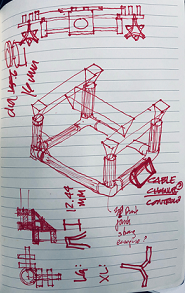
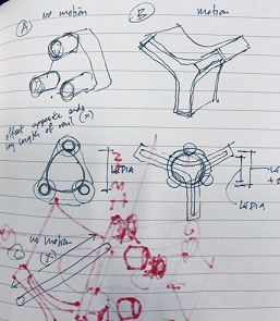
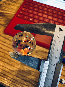
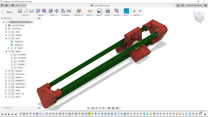
- Inspired by ‘Kinetic Coupling’…the BPM’s X & Y movement systems will essentially be a single ball bearing (superball) moving in between 3 rails arranged in a triangular configuration.
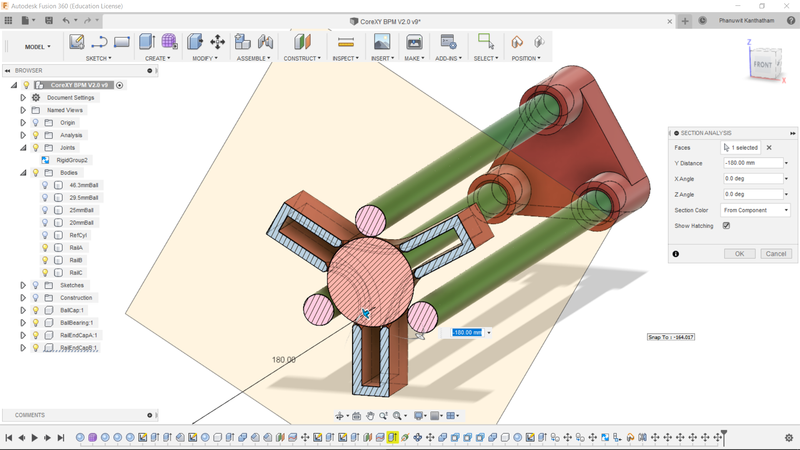
-
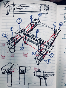
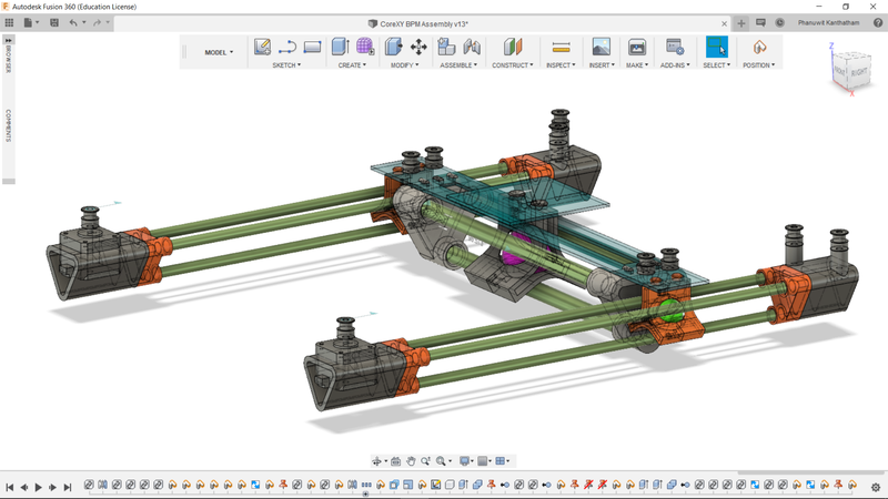
The CoreXY assembly will rest on top of a stout bamboo frame that raises the CoreXY system 30cm above the paper surface to be painted upon.
-
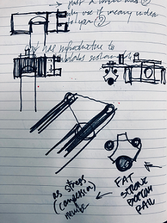
The Mechanical Rail System for X & Y movement will also act as structural stress members of the machine…resisting lateral and bending forces.
A video of the mechanism action…
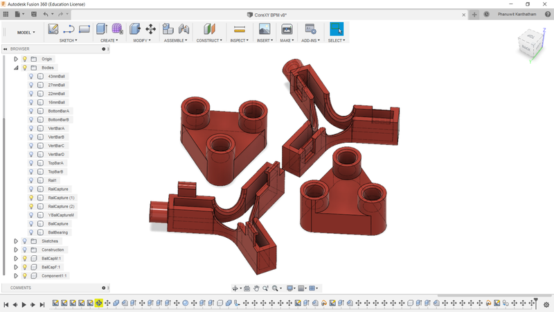
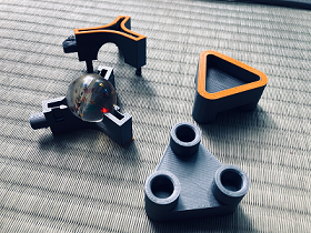
Prototype fabrication
Initial 3D printed prototype parts were designed and fabricated…
Week 15 - Learning Outcome
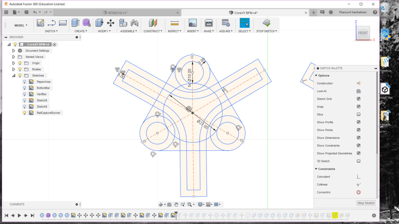
Fusion 360 - Proper parametric design and modeling in Fusion 360 take some intelligent planning. Define parameters that can be utilize in many parts universally. Create distinct parts as ‘Components’ in F360 and ‘Activate’ those components to design and edit…to generate discrete history time lines for each part separate from the whole. - Save each distinct part as its own F360 ‘Unique Part’ file, create a separate, aggregator ‘Virtual Assembly’ file where all the various components can be imported into as ‘Linked Objects’ and put together virtually. Adjustments to individual components should be done in the ‘Unique Part’ file…and simply updated in the ‘Virtual Assembly’ file after.
3D Modeling
- 3D printed parts take a VERY long time to print…and are prone to periodic mid-print failure. A time consuming and inconsistent methodology.
- 3D printed parts are not so precise…with up to 1mm of tolerence errors occurring
- Prusa PLA is pretty stiff, connection tabs that I printed to marry two halfs snapped off instead of bending when I attempted to press it into place…a new connection method (pin & hole) needs to be used.
Miscellaneous Learnings
- The superball will probably prove to be a bad idea…as it is ‘sticky’, i.e. has a high friction coefficient…but I like the inexpensive cost, fun factor and shock absorbing properties of it. Hopefully it will work reasonably well. A bit more clearance will be designed for the capture cavity to hopefully lower the friction problem a bit.
- Finding bamboo of consistent diameter and straightness is hard…hopefully the machine design will have enough ‘sloppiness’ tolerance to still allow the mechnanical systems to work reasonably well to paint ‘artistically’ (i.e. not precisely).