3. Final Project - Electronics Design & Fabrication
With initial device design work progressed enough, it is time to design the electronics to fit inside.
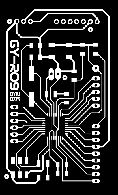
Understanding that it is not enough for me to simply replicate the Satshakit…but knowing that I do not have the knowledge or skill to design a Microcontroller Unit (MCU) from scratch…I chose to modify the Satshakit design to more specifically suit the functional needs of my project. With the base schematic and board design in Eagle previously drawn up, I added…
- 6-pin ISP programming header (which proved indispensible!!!)
- 3-pin connector for my Light Sensor (located separtely from the MCU)
- 7-pin I2C connector for future functionality additions
In addition to the MCU, Electronics Design/Fabrication for my final project also required…
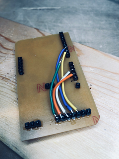
- A Power Junction Board…to be connected with and receive power from a rechargeable battery pack…into which the MCU, 2x Servos, 3x Neopixel light cells will all plug
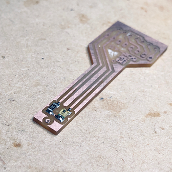
- A remote Sensor board…the light sensor needs visibility to the sky and the future accelerometer needs to be positioned on the top of the device.
Eagle schematic and board routing work is procedural for me at this point…but my minimal understanding of electronics meant that I was uncertain if additions I was making in the design of my boards were correct.
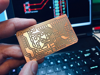
Routing for the extra pins on the MCU board could not successfully be done on top of the board (I would eventually have to correct for missed connections…ground lines and reset lines…by soldering on wires) and some connections were completed under the board by soldering the base of the pins together.
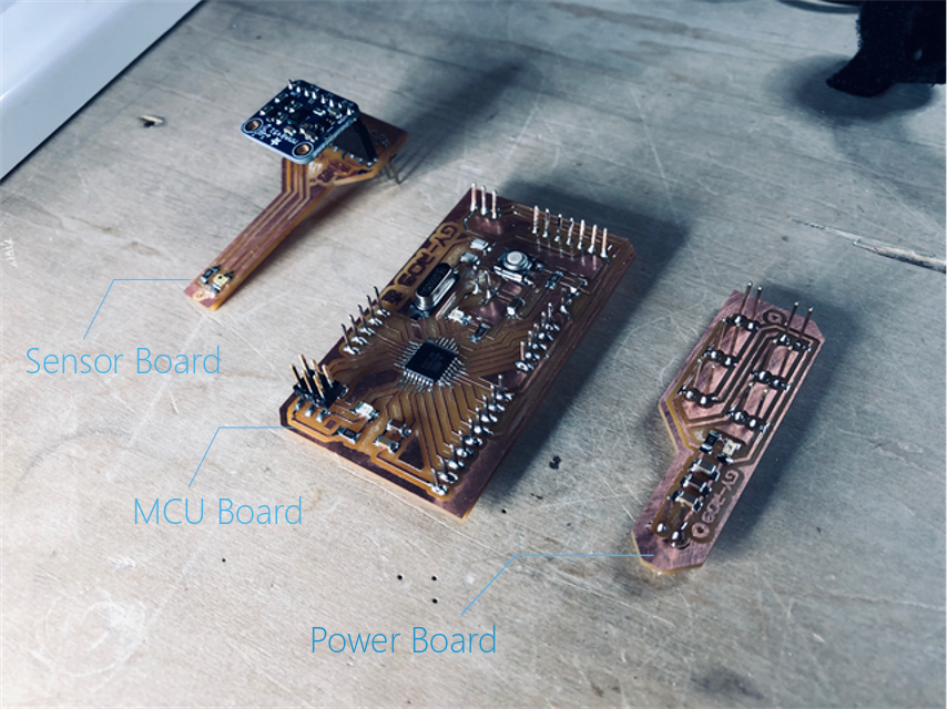
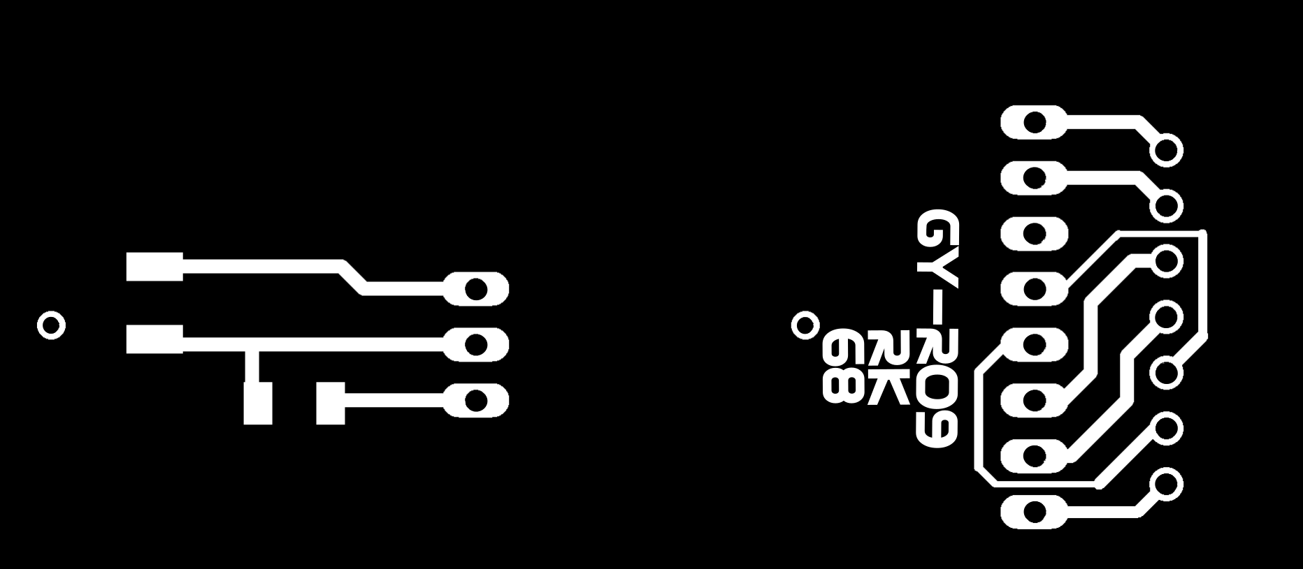
The Sensor Board. The Phototransitor is soldered in place…other sensors would be added via pin connections.
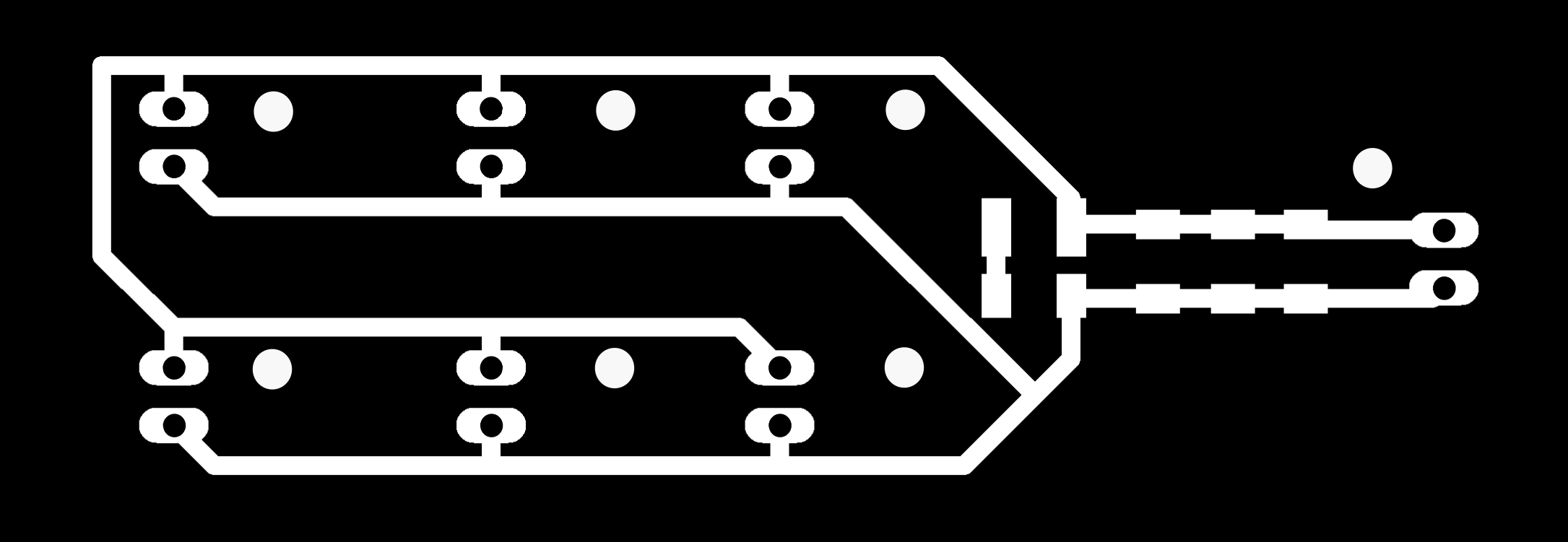
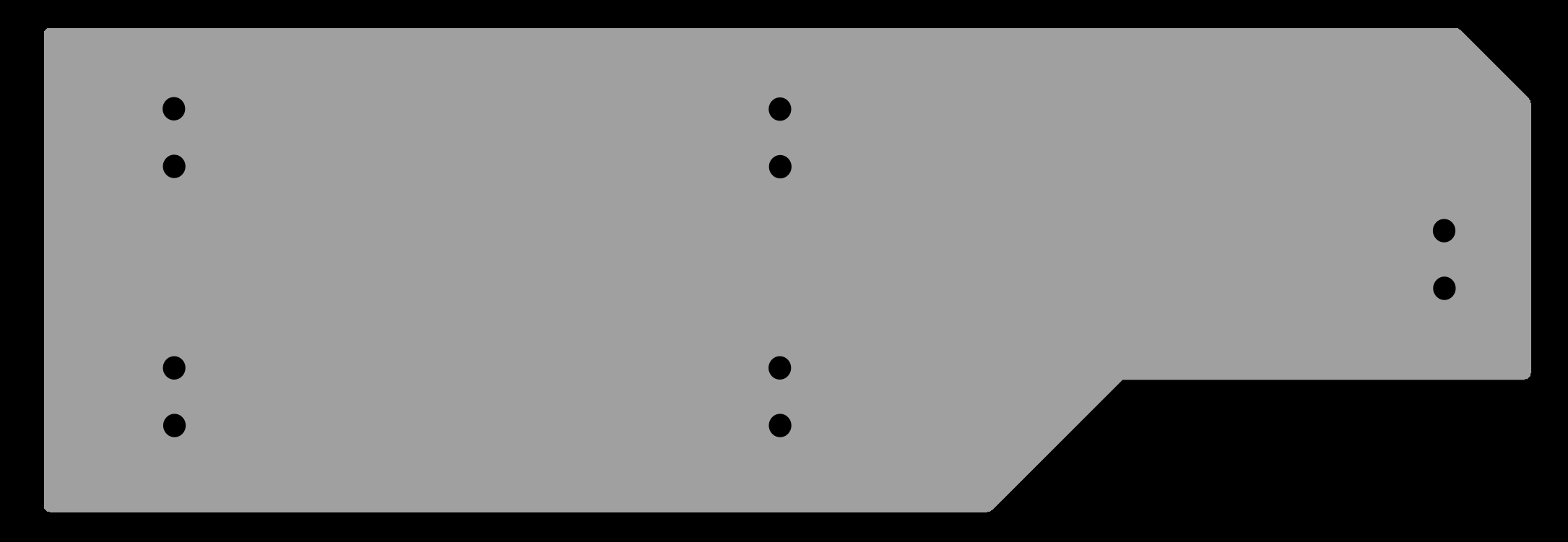
The Power Board. 5V power input from a battery source is tempered by a series of Capacitors to smooth out the current before delivering electricity to 6 5V plugs…2 for Servos, 3 for Neopixels, 1 for the MCU.
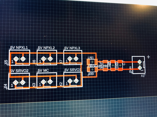
For the Power Junction Board…I replicated the power signal smoothing circuitry from the Satshakit board. For the Sensor board, I replicated the circuitry of Neil’s light sensor board. Without knowing enough about electronics, my strategy was to ‘hack in electronics features” that I know works from boards designed by experts.
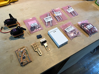
And here are the 3 completed project boards...
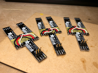
With the 3 boards completed, other electronic components were fabricated…Neopixel light arrays as well as Signal and Power wire harnesses.
- 8 RGB Neopixel sticks wired and soldered together in the the final configuration. I focused to make the wiring as neat and tidy as possible.
- I made my own wiring harness…praying that my wire splicing and connector attaching skills, while novice, will be enough to create a robust end result.
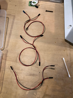
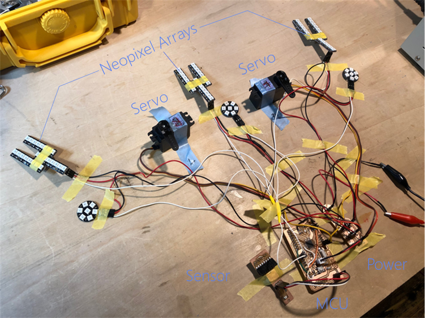
After a lot of cutting, stripping, wiring, and soldering... The full project electronics package, neatly stored and arranged…
…and laid out in testing mode.
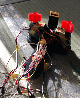
Integrating Electronics into the Device
The Power Board installed in its intended (narrow!) location on the main baseplate. The Sensor Board attached to the opposite end an in a vertical orientation. Two Servos are installed between the boards (with red wing connectors installed on top). Lots of wires that I will have to manage inside the housing. The MCU and Battery is expected be installed over the Power Board.
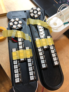
Neopixel Arrays are position on the 3D printed Light Cell baseplate in preparation for fixing to the top of the central Outer Shell and Wings.
With the first stage of Electronics Design/Fabrication completed, I proceeded to programming to activate the boards.
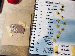
Components
- Microcontroller Board
- Microcontroller: ATMega328
- Connectors:
- Power: Micro USB female connector
- ISP: 3x2 header pins
- I2C: 2x 3-pin, 2x 6-pin female connectors (Sensors)
- PWM: 2x 3-pin female connectors (Servo)
- Digital: 3x 3-pin female connectors (Neopixel)
- Power Regulator: ??
- Neopixel
- 2 Types:
- 9x 8-Pixel “Sticks” (Adafruit)
- 3x 7-Pixel “Coins”
- 5V Power…each individual Neopixel draws up to 60mA at max brightness, 20mA more typical operational power draw (93 pixels x 20mA = 1860mA = 1.8A current draw)
- Any digital pin to send control signal (Pin 6, default)
- 2x Servo
- Tower Pro MG996R
- Torque: 9.4kg/cm
- Operating Voltage: 4.8v to 7.2v (power and signal)
- Running Current: 500mA - 900mA (6V)
- Requires PWM Pins
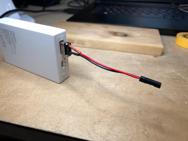
- Battery Power
- Rechargeable 5000mAh LiPO Battery
- Output: 5V 2.1A 12W
- Connector: Type-B MicroUSB
Files
Eagle - Board Design
GYRO9 MCU Schematics here GYRO9 MCU Board Routing here
GYRO9 Sensor Schematics here GYRO9 Sensor Board Routing here
GYRO9 Power Board Schematics here GYRO9 Power Board routing here
PNG Files
GYRO9 MCU Board
GYRO9 Sensor Board

GYRO9 Power Board
RML Files - PCB Milling
GYRO9 MCU Board Trace RMLhere GYRO9 Sensor Board Trace RML here GYRO9 Power Board Trace RML here
GYRO9 MCU Board Outline RML here GYRO9 Sensor Board Outline RML here GYRO9 Power Board Outline RML here
4. Next…Programming >
Appendix - Additional Research
I2C
Pronounced “I squared 2”. Stands for “Inter Integrated Circuitry”…and also well known as “Two Wire Interface”…is a communication protocol. I learned what it is and how to use it by watching these videos
“How i2C Protocol Works” video here
- Inter Integrated circuitry
- A bus system
- serial communication…half duplex mode (?)
- synchronous…needs clock signal
- 2 wires…one data, one clock
- multi-master, multi-slave
- masters generate clock signals..initiates communication
- slaves receives clock…and responds when addressed by master
- short distance intra board communication
- pull up resisters required!!!…to provide voltage
- “Open Drain” or “Open Collector” are typical output configurations..BJT or MOSFET transistors, essentially switches…can have 2 states, either ON or OFF…in i2C “Open Collector arrangement” the control signal is applied to the base terminal of the transistor, whose collector is open and emitter connected to ground…when transistor is turned OFF, because of pull-up resistors, the i2C bus remains at HIGH or Logic 1. When the transistor is turned ON, i2C bus goes to logic 0 due to grounding. To transmit 1 on i2C bus…all the must be turned OFF. And the entire arrangement behaves like wired end(???)
Andreas Spies explains “Multiple Devices on One Arduino i2C Bus” video here
- Arduino, ESP8266 and STM32…talk to i2C via Wire Library
- Attiny 45, 84, 85…talk to i2C via TinyWire Libraryi
- Microcontroller as Master…sensors as slaves
- Arduino i2C_scanner…looks for all addresses on the Bus
- Example sketch connects 2 OLED screens, 1 level shifter, 1 pressure/temperature sensor, 1 touch sensor, 2x i2c bus
“Electronics Basics #19: I2C and how to use it” by Great Scott, video here
- Allows one or more master to talk to up to 127 slave devices…telling them what to do or receive data from them
- synchronous Serial Bus
- SDA connects to Arduino Nano Pin A4
- SCL connects to Arduino Nano Pin A5
- 2x 10k ohm resister acts as ‘Pull-up Resistors’ for SDA and SCL lines…necessary because devices have an “Open Collector” configuration (can only connect the SDA and SCL lines to GND)…to get 2 stable voltage states (to define 2 binary state of Bits) the resistors pull the lines up to 5V
- Datasheets to find specific Bits and HIGH/LOW states needed to send to trigger specific functions
- First…send ‘Start’ condition…SDA falls while SCL stays HIGH…Arduino Wire Library does this automatically when transmission begins (Wire.beginTransmission)
- Second…send the ‘Device Address’ (from datasheet)
- Third…send O or 1 to indicate desire to ‘Write’ or ‘Read’ from the slave, handled automatically by the Arduino library (depending on if ‘beginTransmission’ choosen or ‘requestFrom’)
- Fourth…Acknowledge bit…sent out by slave to let Master know it is ready for the next byte (the data byte)
- Fifth…Stop bit…pulls SDA HIGH and SCL HIGH
“How I2C Communication Works and How to Use It In Arduino” by How To Mechatronics video here
- 128 devices on 7bit addressing
- The SDA and SCL lines are ‘Open Drain’ and require ‘Pull-up Resistors’ to give the lines a HIGH state…the devices connected are ‘Active LOW’
- Common ‘Pull-up’ resistors…2K for 400 kbps (fast) speed, or 10k for 100 kbps (lower) speed
- Data signal transferred in sequences of 8 bits…after a special start condition (1 bit)
- Start (1 bit) + Slave Address (8 bits…last bit indicating R/W) + Acknowlege (1 bit) + Slave Internal Register Address (8 bit) + Acknowledge (1 bit) + Data Sequence(s) (8 bit per sequence…until data completely sent) + Acknowlege (1 bit)+ Stop (1 bit)
- i2C Scanner sketch from Arduino official website…useful to see the ‘Device Addresses’ connected to i2C lines
- Internal Register Addresses…look in the ‘Register Map’ of the device’s datasheet
- Arduino ‘Wire Library’ needs to be included in the sketch for i2C to work…then define ‘Device Address’ and ‘Internal Register Addresses’
Example:
#include <Wire.h>

int ADXLAddress = 0x53;

#define X_Axis_Register_DATAX0 0x32
#define X_Axis_Register_DATAX1 0x33
#define Power_Register 0x2D
The Wire Library will be initiated with the Wire.begin() function…and serial communication initiated and baud rate specified if we want to monitor.
void setup() {
  Wire.begin();
  Serial.begin(9600);
}
To get particular data from the sensor (X axis data in this case)…begin transmission, specify particular internal registers, end transmission.
void.loop() {
  Wire.beginTransmission(ADXLAddress);
  Wire.write(X_Axis_Register_DATAX0);
  Wire.write(X_Axis_Register_DATAX1);
  Wire.endTransmission();
}
Then read data from those internal registers with Wire.requestFrom function, specifying the number of Bytes wanted…the Wire.available function will return the number of Bytes available for retrieval…if requested Bytes and available Bytes match…data retrieval occurs
``` Wire.requestFrom(ADXLAddress,2);
if (Wire.available()<=2) { X0 = Wire.read(); X1 = Wire.read(); }
``` The print the data in the serial monitor…
  Serial.print("X0 = ");
  Serial.println(X0);
  Serial.print("      x1 = ");
  Serial.println(X1);
“Connecting Arduino with Multiple i2C devices” by BlueDot video here
Pull-Up Resistors
- The two lines in i2C are “open drain”…
- Pull-up resistors need to be attached to them so they become HIGH…because the devices on the i2C bus are “Active LOW”
- Commonly used resisters…2k for higher speeds, at 400 kbps or up to 10k at slower speed of 100kbps
Open Drain vs Open Collector configurations
- “Open Collector” is a ‘current sink’ (current is flowing into the pin not out of the pin) on a transistor output. If an NPN transistor is left unconnected, or open but connected to an external pin…the transistor will switch to GND when active…sinking the current. BJT
- “Open Drain” means there’s a ‘current sink’ on a FET device. MOSFET
- An Open Drain or Open Collector output pin is simply a pin driven by a single transistor, either MOSFET or BJT, respectively.
- The main po9int in the term Open Drain or Collector is that part of the output transistor is directly brought out to a pin that is external to the IC package
- Open-collector and drain devices sink current when controlled to one state and have no current flow in the other state. It is fairly common to use open-drains together with a pull-up resistor. The pull-up resistor is connecte dot HIGH (supply voltage) at one end and connected to one or more external pins of the open-drain/collector devices all connected together. Thus if any one of the open-drain devices is set to sink current, current flow for all of the devices gets sunk to the ground, since they are all connected at the same point.
- That holds the signal line high until a device on the wire sinks enough current to pull the line low. Many devices can be attached to the signal wire. If all devices attached to the wire are in their non-active state, the pull-up will hold the wire at a HIGH voltage. If one or more devices are in the active state, the signal wire voltage will be LOW. Basically, the circuit has a resistor between it and the path to 5V (pull-up resistor). Pull-up resistors are used so that when the FET is OFF the wire will float to the HIGH voltage, which is usually supply voltage for the circuit.
MOSFET vs BJT
A full great explanation by Talesa Bleything here
- MOSFET = Metal Oxide Field-Effect Transistor
- Voltage driven device…and Unipolar, allowing one type of charge (either holes or electrons) to flow
- …have 3 different terminals Source (like BJT Emitter), Drain (like Collector) and Gate (like Base)
- N and P types
- ‘N-channel’…source connected to GND, device activated by applying a positive voltage to Gate. This creates an electric field (field effect) and allows electrons to flow in a thin channel from Source to Drain. N-type are more commonly used.
- ‘P-channel’…Source is connected to VCC and device activated by connecting the gate to GND. Holes (instead of electrons) are the charge carrier
- Logic level MOSFETs can be used similarly to BJT…but more expensive and harder to find than standard MOSFETs, which needs 10V or more to turn on
- Infinitely high input impedence…useful in power Amplifiers
- More power efficient and tolerant to heat than BJT
- Fast enough switching under 1Mhz
- MOSFET = high input impedence and low power consumption
- BJI = Bipolar Junction Transistor
- Current driven Devices…Bipolar
- …comes in 2 types…NPN (one layer of p-type silicon sandwiched between two layers of n-type) and PNP (vice versa)
- Each layer has a specific name…Collector (top), Base (middle), Emitter (bottom)
- Operation principals for each type nearly identical…the functional difference lies in biasing of the junctions
- NPN: when positive bias applied to base of NPN, device turned ON and current flows from Emitter to Collector…known as ‘Low-side Switch’, Emitter connects to GND and Collector to the load.
- PNP: when negative bias is applied to the base of a PNP transitor, the device is turned ON and current flows from the Collector to Emitter…’High-side Switch’ the Emitter connects to the VCC and the Collector connects to the load.
- BJT handy for driver low-power LEDs from common microcontrollers that can only output 5V DC (…like Arduino)
- Switch faster than MOSFETs…good for high-freq applications
- less power efficient than MOSFETs…not good for battery-powered applications where load is variable
- BJT = Very high frequency operation and high current drive capability
- …similar functions different characteristics
- Both can be used as ‘Amplifiers’ or ‘ Swithches’
- ‘Amplifier’…take in a small current at one end and produce a much larger current on the other end. useful in analog circuits where transistors form the basis of components.
- ‘Switch’…a small current through one part of the transistor can switch on the larger current through another part of it. The transistor can be in 2 distinct states and represent 2 different values: 0 or 1, OFF or ON.
- Transistors are silicon based, electrically neutral, defined as ‘semiconductor’…neither a great conductor nor great insulator of electricity. Behavior can be altered by adding impurities.
- ‘Doping’ is a process to add chemical impurities to silicon
- ‘N-type’ or ‘Negative type’ is doping to add extra ‘free’ electrons and make it more readily to carry electric current
- ‘P-type’ or ‘Positive type’ has fewer electrons, having ‘holes’ where electrons should be
- Neither type N or P are electrically charged…can be joined together and the electrons and holes will not begin to cross the n-p junction until an electric current (BJT)…or voltage (MOSFET) is applied.
Current vs voltage…and Ohm’s Law
- ‘Current’ = the RATE at which electric charge flows (flow…in a water flow analogy), RATE of FLOW…measured in ‘Amperes or Amps’ and represented by ‘I’
- ‘Voltage’ = electromotive force (pressure…in a water flow analogy), is the potential difference in charge between 2 points in an electrical field…the potential energy between 2 points…measured in ‘Volts’ represented by ‘V’
- ‘Voltage’ is the cause and ‘Current’ is the effect
- ‘Ohm’s Law’ is V = I * R
- Resistance = a material’s tendency to resist the flow of charge (current)…measured in ‘Ohms’ and represented by ‘R’
- ‘Charge’ = (amount of water…in a water flow analogy) measured in ‘Coulombs’
Sensor Research
- Light: Adafruit TSL2561
(will need window to the sky in housing…)
Description: Luminosity sensor, more precise than CdS cells, exact lux calculations can be configured for different gain/timing ranges to detect
Range: 0.1-40,000+ lux
Measurability: contains both infrared and full spectrum diodes…can measure separately (elim infra to detect only human “broadband” visible light)
Power: 2.7v-3.6v…handled with level shifting 3.3v regulator…usable with 3-5V power/logic Microcontroller. Low current draw,..0.5mA when actively sensing, less than 15uA when in powerdown model
ADC: built in ADC…can be used with any microcontroller…even if it doesn’t have analog inputs
Serial Communication: 9600 baud rate
- To manually read the individual photo diodes…call the getLuminosity function and passing two variables where the sensor data will be stored (broadband vs infrared); I will read Broadband values, set a level to turn device on/off.
-
Returns light in standard SI lux units
- I2C…3 addresses can be selected from
- - Need to configure the ‘Gain’ and ‘Integration Time’ - Gain: 0 (no gain) good in low light situations, 16 boosts the light in dim situations…leave at 0 - Integration Time: how long it will collect light data for…the longer the time, the more precision the sensor has (can it be just left collecting continuously??) - Pins: - Vin: - GND: - 3v3: - ADDR: i2C address change pin…used if addresss conflict…connect to GND to select address 0x29, to VCC to select 0x49, or unconnected (floating) to use 0x39 - INT: interrupt output pin from the sensor…connect only if sensor configured to signal when light level has changed (YES!!!! I will use this!!!)…use a 10k-100k pullup from INT to 3.3V (VCC) if used in this way - Arduino: Adafruit_TSL2561 Library - Physical Installation: need window to the sky
test: room light 110lux, room light off…door cracked 1lux…then overload (need to increase gain to deal with pitch dark?). 20lux = dusk? set gain to 5?
set gain to 16x (seems choices are auto, 0x, or 16x) - phone light shining a few cm on top of sensor gets 3200+ lux…not overload - dark test: overloads in semi-darkness…will this cause problems with Neopix on s
- Accelerometer: Adafruit MMA8451
- 3V sensor
- 3.3v regulator and level shifting circuitry on board…can be used with 3-5v power/logic supply
- i2C…this chip requires “repeated-start i2C” support (??) (to port this to another processor)
- 9600 baud serial connection
- Detect motion, tilt and basic orientation
- Tilt/Orientation detection: can tell if in landscape or portrait mode, tilted forward or back (Still need gyro for specific angle data!!!)
- low cost, high precision
- 14-bit ADC
- range from +/-2g, +/-4g or +/-8g
- MMA8451 manuf by Freescale…most precise in comparison with MMA8452 and MMA8453
- pins:
- Vin:
- 3Vo: 3.3v output from voltage regulator…can grab 100mA from this pins
- GND:
- SCL:
- SDA:
- A: address select pin…pulled up to 3.3v with 10k resistor for i2C address of 0x1D, if connected to GND then address chgs to 0x1C
- i1: Interrupt 1 signal pin…for advance use, where you want to be alerted by the chip when data is ready to read or if it detects a large motion (YES!!! I will use this Interrupt Pin)
- i2: Interrupt 2 signal pin
- Arduino:
- Measure for: G…specifying trigger point G levels…in any direction. Set Sensitivity to +/-4g or +/-8g probably
test: works well. not settings to adjust.
- Triple Axis Gyro: Adafruit L3GD20H
- Sense twist and turning motions…paired with accelerometer typically…for 3D motion capture and inertial measurement (how an object is moving)
- L3GD20H Manuf by STMicro, upgrade to L3G4200
- +/-250, +/-500 or +/-2000 degree-per-second (I probably need the lowest one…)
- Built in high and low pass sensing to make data processing easier
- i2C and SPI support…i2C addres 0x6B
- 3.3v Max…3.3v regulator with level-shifting…can be powered with 5V
- 4x 2.1mm mounting hole (will need these #2-56 imperial or M2 screws) to allow firm mounting
- 9600 baud rate
Test: Bumped range to 500dps - x y figures not absolute but relative…after moving the gyro to a new position…after displaying numbers to show change of position…the gyro resets x y to zero at the new angled position
- Temperature & Humidity: Adafruit Si7021
- I2C (address 0x40)…2 clock/data wires on microcontroller used (shareable with other sensors as long as addresses differ); no pins to set, must use the I2C bus!
- 115200 baud serial rate
- 3.3v Regulator, level-shifting…safe to use with 3.3v or 5V power & logic
- 0 to 80% RH, +/- 3% relatively humidity measurements; measuring change in capacitance…must keep sensor clean and free of dust and other contaminant
- -10 to +85 C, +/- 0.4% C Temperature measurement (convert to Farenheit by multiplying by 1.8 and adding 32)
- PTFE filter to keep the sensor clean (white thing on top)
- Pins
- Vin: Power…the chip uses 3VDC, a regulator is included; give the board the same power as the ‘logic level’ of the Microcontroller
- 3v3: 3.3v output from voltage regulator…100mA can be grabbed from this
- GND: ground for power and logic
- SCL: I2C clock pin…connect to microcontroller I2C clock line
- SDA: I2C data pin…connect to microcontroller’s I2C data line
- Arduino: Adafruit_Si7021 Library
- Code:
- Create Object: Adafruit_Si7021 sensor = Adafruit_Si7021
- Initialize Sensor: sensor.begin()…returns TRUE if sensor found
- Query Temperature: sensor.readTemperature()…returns floating point temp in C
- Query Humidity: sensor.readHumidity()…returns floating point value between 0 and 100