14. Networking and communications
This week I worked on exploring networking microcontroller boards. Through many mistakes about the capabilities of both serial and i2c communiction, I learned a lot about each of them.
All final code and design files for this week can be found here while the secondary boards I used can be found here and here (note that the code of the secondary boards is not the same as the code as in the zip files with their board design files but rather is included in the zip file for this week).
Research
I chose to use serial communication since my input already used the i2c pins for the 3d hall effect sensor. To get an idea of what pins I needed for the main, I looked at Adrian Torres’s documentation. I saw that I needed to have shared ground and power with tx and rx busses for communication.
Later, however, I would realize that i2c would be more suitable for my needs.
Board design
I used the boards from my input and output weeks as nodes.
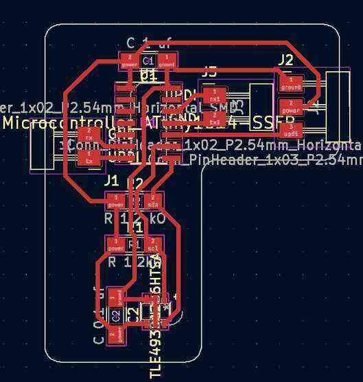
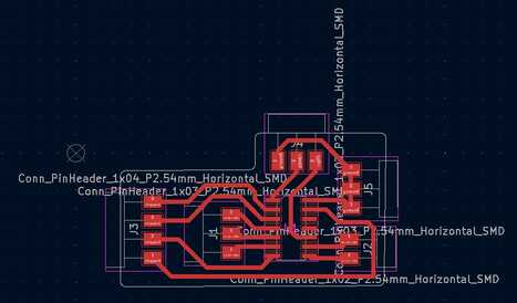
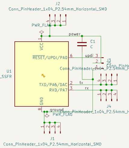
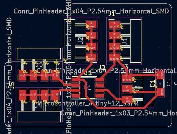
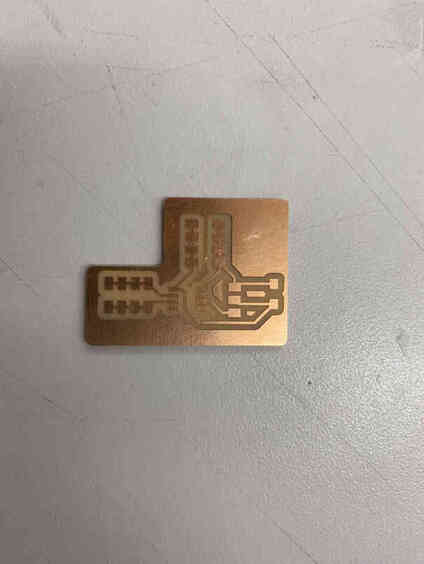
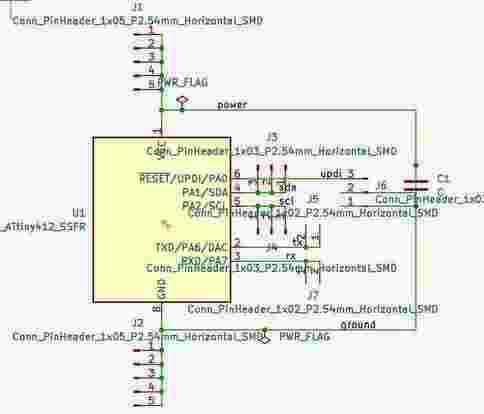
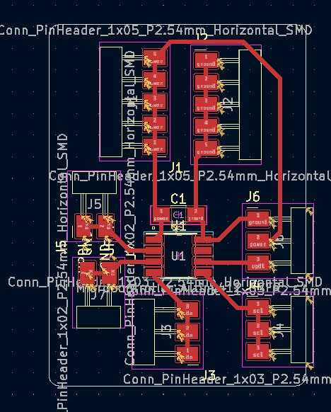
I made a new board to act as the main. I used shared ground and power headers as well as headers for both tx and rx that would support 4 nodes just in case I would later add more.
I then milled the board, and it turned out fine.
Code
I referenced Dr. Gershenfeld’s code for the way he processed the data from the 3d hall effect sensor, and I started with this code, but it was not working at all. I did some thinking, and I found the section of code that was causing the issues. In my secondary boards, I had sections that would read in some values and throw them away to account for the other one sending data to the main board, but since the tx pins of those are connected together to the rx of the main board, the transmittion would only go through to the main board since only it has a recieve pin connected.
Main board code
The setup begins serial communication with a delay to make sure the secondary boards have begun serial communication before sending anything.
The loop starts with requesting data from the input board then processes it to determine the number of steps needed to move for the stepper motor and sends that to the output board. It then waits for the output board to send back that it is done stepping before moving on.
#define NODE 0

const float stepDist = 0.06;
void setup() {
  // put your setup code here, to run once:
  Serial.begin(9600);
  delay(10000);
}

float xpos = 0;

void loop() {
  // put your main code here, to run repeatedly:
  Serial.println(1);
  int data[6];
  for (int i = 0; i < 6; ++i) {
    while (Serial.available() == 0);
    data[i] = Serial.parseInt();
  }
  int newx = (data[0] << 4) + ((data[4] & 0xF0) >> 4);
  int steps = 0;
  while (xpos < newx) {
    ++steps;
    xpos += stepDist;
  }
  while (xpos > newx) {
    --steps;
    xpos -= stepDist;
  }
  Serial.println(2);
  Serial.println(steps);
  while (Serial.available() == 0);
  Serial.parseInt();
  delay(500);
}
Input board code
The setup starts serial communication and starts i2c communication with the sensor.
The loop checks to see if the main board is requesting data and then sends it if it is, and if it isn’t then it waits for some serial communication, which is above discussed as an error.
#include <Wire.h>

#define NODE 1
#define address 0x35

void setup() {
  // put your setup code here, to run once:
  Serial.begin(9600);
  Wire.begin();
  Wire.setClock(400000);
  //
  // reset TLE493D
  //
  Wire.beginTransmission(address);
  Wire.write(0xFF);
  Wire.endTransmission();
  Wire.beginTransmission(address);
  Wire.write(0xFF);
  Wire.endTransmission();
  Wire.beginTransmission(address);
  Wire.write(0x00);
  Wire.endTransmission();
  Wire.beginTransmission(address);
  Wire.write(0x00);
  Wire.endTransmission();
  delayMicroseconds(50);
   //
   // configure TLE493D
   //
  Wire.beginTransmission(address);
  Wire.write(0x10);
  Wire.write(0x28);
      // config register 0x10
      // ADC trigger on read after register 0x05
      // short-range sensitivity
  Wire.write(0x15);
      // mode register 0x11
      // 1-byte read protocol
      // interrupt disabled
      // master controlled mode
  Wire.endTransmission();
}

void loop() {
  // put your main code here, to run repeatedly:
  uint8_t data[6];
   //
   // read data
   //
  while (Serial.available() == 0);
  int inputNode = Serial.parseInt();
  if (inputNode == NODE) {
    Wire.requestFrom(address,6);
    for (int i = 0; i < 6; ++i) {
     data[i] = Wire.read();
    }
    for (int i = 0; i < 6; ++i) {
     Serial.println(data[i]);
    }
  } else if (inputNode == 2) {
    for (int i = 0; i < 2; ++i) {
      while (Serial.available() == 0);
      Serial.parseInt();
    }
  }
}
Output board code
It starts off with a class definition for the stepper motor from my week 11 assignment.
The setup starts serial communication and sets the pins for the stepper motor as outputs.
The loop checks to see if the main board is telling this board to move the motor and moves the motor if it is, and if it isn’t then it waits for some serial communication, which is above discussed as an error.
#define NODE 2

class Stepper {
  private:
  int pin1shift, pin2shift, pin3shift, pin4shift;
  volatile byte& reg1;
  volatile byte& reg2;
  volatile byte& reg3;
  volatile byte& reg4;
  int stepPos;
  int delayTime;

  public:
  Stepper(volatile byte& r1, int p1, volatile byte& r2, int p2, volatile byte& r3, int p3, volatile byte& r4, int p4, int del): pin1shift(p1), reg1(r1), pin2shift(p2), reg2(r2), pin3shift(p3), reg3(r3), pin4shift(p4), reg4(r4), delayTime(del) {
    stepPos = 0;
  }

  private:
  void out1() {
    reg1 |= 1 << pin1shift;
  }

  void clear1() {
    reg1 &= ~(1 << pin1shift);
  }

  void out2() {
    reg2 |= 1 << pin2shift;
  }

  void clear2() {
    reg2 &= ~(1 << pin2shift);
  }

  void out3() {
    reg3 |= 1 << pin3shift;
  }

  void clear3() {
    reg3 &= ~(1 << pin3shift);
  }

  void out4() {
    reg4 |= 1 << pin4shift;
  }

  void clear4() {
    reg4 &= ~(1 << pin4shift);
  }

  void runStep() {
    switch (stepPos) {
      case 0:
      out1();
      clear2();
      out3();
      clear4();
      break;
      case 1:
      clear1();
      out2();
      out3();
      clear4();
      break;
      case 2:
      clear1();
      out2();
      clear3();
      out4();
      break;
      case 3:
      out1();
      clear2();
      clear3();
      out4();
      break;
    }
    delay(delayTime);
  }

  public:
  void stepCW(int numSteps) {
    for (int i = 0; i < numSteps; ++i) {
      stepPos = (stepPos + 1) % 4;
      runStep();
    }
  }

  void stepCCW(int numSteps) {
    for (int i = 0; i < numSteps; ++i) {
      --stepPos;
      if (stepPos < 0) stepPos = 3;
      runStep();
    }
  }
};

void setup() {
  // put your setup code here, to run once:
  PORTA.DIRSET |= 1 << 4;
  PORTA.DIRSET |= 1 << 5;
  PORTB.DIRSET |= 1 << 0;
  PORTB.DIRSET |= 1 << 1;
  Serial.begin(9600);
}

Stepper myStepper(PORTA.OUT, 4, PORTA.OUT, 5, PORTB.OUT, 0, PORTB.OUT, 1, 10);

void loop() {
  // put your main code here, to run repeatedly:
  while (Serial.available() == 0);
  int nodeInput = Serial.parseInt();
  if (nodeInput == NODE) {
    while (Serial.available() == 0);
    int steps = Serial.parseInt();
    if (steps < 0) myStepper.stepCCW(steps * -1);
    else myStepper.stepCW(steps);
    Serial.println(1);
  } else if (nodeInput == 1) {
    for (int i = 0; i < 6; ++i) {
      while(Serial.available() == 0);
      Serial.parseInt();
    }
  }
}
I removed the erraneous sections and ended up with this code. The code largely remained the same as above except removing the else if statements from the 2 secondary boards. That did not entirely work, but it got the motor moving, so data was definitely being received and sent meaning it was a step in the right direction.
At this point, I thought the only possible reasons for failure were that either the data from the sensor was wrong or the code was getting stuck at the end of the void loop, so it couldn’t begin again and update. I didn’t think the first was very likely due to my testing during input week as well as the fact that even if the values were wrong, they would at least change and cause some movement and the fact that it could read values the first time through. As for the second, I couldn’t find a reason it would get stuck. Another peculiar thing that happened was that when I tried to investigate this by having the serial also go into my computer for the serial monitor, it would stop working entirely, but after disconnecting the serial connection to my computer and resetting the boards by unplugging and repluggin them into power, it started working again.
I sought help from Jeremy, an engineer who came to our lab and learned that the problem was that I was trying to transmit back to the main board through serial using 2 secondary boards. When the transmission ended, the line would either be set to high or low. If it was high, the other board would not be able to pull it low and send, but if it was low, when the other secondary board transmits, it shorts into this secondary board instead of reaching the main board. Two ways to fix this were to either implementing tristate when not transmitting or using i2c instead.
I decided to use a mixture of i2c and serial since serial would be needed for my input board since it is already acting as a main board for my input with i2c, and using i2c for the output board would eliminate the problem I was having with serial.
Board design (i2c)
My input and output boards remained the same, but I changed the main board to include an i2c bus.
Code (i2c)
I started off trying to test with just the main board and the output board with the following code, but it didn’t work and was making unexpected movements.
Main board code
#include <Wire.h>

#define XADDRESS 0x08

void setup() {
  // put your setup code here, to run once:
  Wire.begin();
  PORTA.PIN2CTRL |= 1 << 3;
  PORTA.PIN1CTRL |= 1 << 3;
  Wire.setClock(400000);
  delay(5000); //waits just in case secondary boards have not yet set up
}

void loop() {
  // put your main code here, to run repeatedly:
  int steps = 200;
  sendSteps(steps, XADDRESS);
  delay(100);
  steps = -200;
  sendSteps(steps, XADDRESS);
  delay(100);
}

void sendSteps(const int& steps, const byte address) {
  Wire.beginTransmission(address);
  uint8_t byte1 = (steps & 0xFF00) >> 8;
  uint8_t byte2 = steps & 0x00FF;
  Wire.write(byte1);
  Wire.write(byte2);
  Wire.endTransmission();
  // waits for output board to send back indicating that it is done moving
  Wire.requestFrom(address, 1);
}
Output board code
#include <Wire.h>

#define ADDRESS 0x08

class Stepper {
  private:
  int pin1shift, pin2shift, pin3shift, pin4shift;
  volatile byte& reg1;
  volatile byte& reg2;
  volatile byte& reg3;
  volatile byte& reg4;
  int stepPos;
  int delayTime;

  public:
  Stepper(volatile byte& r1, int p1, volatile byte& r2, int p2, volatile byte& r3, int p3, volatile byte& r4, int p4, int del): pin1shift(p1), reg1(r1), pin2shift(p2), reg2(r2), pin3shift(p3), reg3(r3), pin4shift(p4), reg4(r4), delayTime(del) {
    stepPos = 0;
  }

  private:
  void out1() {
    reg1 |= 1 << pin1shift;
  }

  void clear1() {
    reg1 &= ~(1 << pin1shift);
  }

  void out2() {
    reg2 |= 1 << pin2shift;
  }

  void clear2() {
    reg2 &= ~(1 << pin2shift);
  }

  void out3() {
    reg3 |= 1 << pin3shift;
  }

  void clear3() {
    reg3 &= ~(1 << pin3shift);
  }

  void out4() {
    reg4 |= 1 << pin4shift;
  }

  void clear4() {
    reg4 &= ~(1 << pin4shift);
  }

  void runStep() {
    switch (stepPos) {
      case 0:
      out1();
      clear2();
      out3();
      clear4();
      break;
      case 1:
      clear1();
      out2();
      out3();
      clear4();
      break;
      case 2:
      clear1();
      out2();
      clear3();
      out4();
      break;
      case 3:
      out1();
      clear2();
      clear3();
      out4();
      break;
    }
    delay(delayTime);
  }

  public:
  void stepCW(int numSteps) {
    for (int i = 0; i < numSteps; ++i) {
      stepPos = (stepPos + 1) % 4;
      runStep();
    }
  }

  void stepCCW(int numSteps) {
    for (int i = 0; i < numSteps; ++i) {
      --stepPos;
      if (stepPos < 0) stepPos = 3;
      runStep();
    }
  }
};

bool moving = false;

void setup() {
  // put your setup code here, to run once:
  Wire.begin(ADDRESS);
  PORTA.DIRSET |= 1 << 4;
  PORTA.DIRSET |= 1 << 5;
  PORTA.DIRSET |= 1 << 3;
  PORTB.DIRSET |= 1 << 2;
  Wire.onReceive(doStep);
  Wire.onRequest(notMoving);
}

Stepper myStepper(PORTA.OUT, 4, PORTA.OUT, 5, PORTB.OUT, 2, PORTA.OUT, 3, 10);

void loop() {
  // put your main code here, to run repeatedly:
  delay(10);
}

void doStep(int numBytes) {
  moving = true;
  int steps = Wire.read() << 8;
  steps |= Wire.read();
  if (steps < 0) myStepper.stepCCW(steps * -1);
  else myStepper.stepCW(steps);
  moving = false;
}

void notMoving() {
  while (moving);
  Wire.write((byte) 1);
}
After doing some tests with the serial monitor, I realized that it was sending and recieving the right data, and I knew that the stepper motor code worked from output week, so with some more testing, I realized that i2c starts to have some unexpected behaviour when delays are in the request or recieve events, so I removed the delays from the output board and instead had the main board handle more of it, and that worked with the following code.
Main board code
#include <Wire.h>

#define XADDRESS 0x08

const float stepDist = 0.06;
float pos = 0.0;
void setup() {
  // put your setup code here, to run once:
  Serial.begin(9600);
  Wire.begin();
  PORTA.PIN2CTRL |= 1 << 3;
  PORTA.PIN1CTRL |= 1 << 3;
  Wire.setClock(400000);
  delay(5000); //waits just in case secondary boards have not yet set up
}

void loop() {
  // put your main code here, to run repeatedly:
  int steps = 200;
  sendSteps(steps, XADDRESS);
  delay(100);
  steps = -200;
  sendSteps(steps, XADDRESS);
  delay(100);
}

void sendSteps(const int& steps, const byte address) {
  if (steps < 0) {
    for (int i = 0; i < steps * -1; ++i) {
      Wire.beginTransmission(address);
      int8_t val = -1;
      Wire.write(val);
      Wire.endTransmission();
      delay(10);
    }
  } else {
    for (int i = 0; i < steps; ++i) {
      Wire.beginTransmission(address);
      int8_t val = 1;
      Wire.write(val);
      Wire.endTransmission();
      delay(10);
    }
  }
}
Output board code
#include <Wire.h>

#define ADDRESS 0x08

class Stepper {
  private:
  int pin1shift, pin2shift, pin3shift, pin4shift;
  volatile byte& reg1;
  volatile byte& reg2;
  volatile byte& reg3;
  volatile byte& reg4;
  int stepPos;
  int delayTime;

  public:
  Stepper(volatile byte& r1, int p1, volatile byte& r2, int p2, volatile byte& r3, int p3, volatile byte& r4, int p4, int del): pin1shift(p1), reg1(r1), pin2shift(p2), reg2(r2), pin3shift(p3), reg3(r3), pin4shift(p4), reg4(r4), delayTime(del) {
    stepPos = 0;
  }

  private:
  void out1() {
    reg1 |= 1 << pin1shift;
  }

  void clear1() {
    reg1 &= ~(1 << pin1shift);
  }

  void out2() {
    reg2 |= 1 << pin2shift;
  }

  void clear2() {
    reg2 &= ~(1 << pin2shift);
  }

  void out3() {
    reg3 |= 1 << pin3shift;
  }

  void clear3() {
    reg3 &= ~(1 << pin3shift);
  }

  void out4() {
    reg4 |= 1 << pin4shift;
  }

  void clear4() {
    reg4 &= ~(1 << pin4shift);
  }

  void runStep() {
    switch (stepPos) {
      case 0:
      out1();
      clear2();
      out3();
      clear4();
      break;
      case 1:
      clear1();
      out2();
      out3();
      clear4();
      break;
      case 2:
      clear1();
      out2();
      clear3();
      out4();
      break;
      case 3:
      out1();
      clear2();
      clear3();
      out4();
      break;
    }
    delay(delayTime);
  }

  public:
  void stepCW(int numSteps) {
    for (int i = 0; i < numSteps; ++i) {
      stepPos = (stepPos + 1) % 4;
      runStep();
    }
  }

  void stepCCW(int numSteps) {
    for (int i = 0; i < numSteps; ++i) {
      --stepPos;
      if (stepPos < 0) stepPos = 3;
      runStep();
    }
  }
};

void setup() {
  // put your setup code here, to run once:
  Wire.begin(ADDRESS);
  PORTA.DIRSET |= 1 << 4;
  PORTA.DIRSET |= 1 << 5;
  PORTA.DIRSET |= 1 << 3;
  PORTB.DIRSET |= 1 << 2;
  Wire.onReceive(doStep);
}

Stepper myStepper(PORTA.OUT, 4, PORTA.OUT, 5, PORTB.OUT, 2, PORTA.OUT, 3, 0);

void loop() {
  // put your main code here, to run repeatedly:
  delay(10);
}

void doStep(int numBytes) {
  int8_t steps = Wire.read();
  if (steps < 0) myStepper.stepCCW(1);
  else myStepper.stepCW(1);
}
I then added the input board with the following code while keeping the output board code the same, and that worked and the stepper motor responded to moving a magnet. It fluctuated a bit back and forth even when the magnet was still since there were fluctuations in the input readings by 1 back and forth, but it still responded well.
Main board code
#include <Wire.h>

#define XADDRESS 0x08

const float stepDist = 0.06;
float pos = 0.0;
void setup() {
  // put your setup code here, to run once:
  Serial.begin(9600);
  Wire.begin();
  PORTA.PIN2CTRL |= 1 << 3;
  PORTA.PIN1CTRL |= 1 << 3;
  Wire.setClock(400000);
  delay(5000); //waits just in case secondary boards have not yet set up
}

void loop() {
  // put your main code here, to run repeatedly:
  Serial.println(1);
  int data[3];
  for (int i = 0; i < 3; ++i) {
    while (Serial.available() == 0);
    data[i] = Serial.parseInt();
  }
  int steps = 0;
  while (pos < data[0]) {
    ++steps;
    pos += stepDist;
  }
  while (pos > data[0]) {
    --steps;
    pos -= stepDist;
  }
  sendSteps(steps, XADDRESS);
}

void sendSteps(const int& steps, const byte address) {
  if (steps < 0) {
    for (int i = 0; i < steps * -1; ++i) {
      Wire.beginTransmission(address);
      int8_t val = -1;
      Wire.write(val);
      Wire.endTransmission();
      delay(10);
    }
  } else {
    for (int i = 0; i < steps; ++i) {
      Wire.beginTransmission(address);
      int8_t val = 1;
      Wire.write(val);
      Wire.endTransmission();
      delay(10);
    }
  }
}
Input board code
#include <Wire.h>

#define NODE 1
#define address 0x35

void setup() {
   //
   // start serial and I2C
   //
   Serial.begin(9600);
   Wire.begin();
   Wire.setClock(400000);
   //
   // reset TLE493D
   //
   Wire.beginTransmission(address);
   Wire.write(0xFF);
   Wire.endTransmission();
   Wire.beginTransmission(address);
   Wire.write(0xFF);
   Wire.endTransmission();
   Wire.beginTransmission(address);
   Wire.write(0x00);
   Wire.endTransmission();
   Wire.beginTransmission(address);
   Wire.write(0x00);
   Wire.endTransmission();
   delayMicroseconds(50);
   //
   // configure TLE493D
   //
   Wire.beginTransmission(address);
   Wire.write(0x10);
   Wire.write(0x28);
      // config register 0x10
      // ADC trigger on read after register 0x05
      // short-range sensitivity
   Wire.write(0x15);
      // mode register 0x11
      // 1-byte read protocol
      // interrupt disabled
      // master controlled mode
   Wire.endTransmission();
}

void loop() {
   uint8_t data[6];
   int transformedData[3];
   while (Serial.available() == 0);
   int inputNode = Serial.parseInt();
   if (inputNode == NODE) {

     //
     // read data
     //
     Wire.requestFrom(address,6);
     for (int i = 0; i < 6; ++i) {
      data[i] = Wire.read();
     }

     transformedData[0] = (data[0] << 4)+((data[4] & 0xF0) >> 4);
     transformedData[1] = (data[1] << 4)+(data[4] & 0x0F);
     transformedData[2] = (data[2] << 4)+(data[5] & 0x0F);

     for (int i = 0; i < 3; ++i) {
      if (transformedData[i] > 2047) transformedData[i] -= 4096;
      Serial.println(transformedData[i]);
     }
   }
}
Wiring
The arduino was only used to supply 3.3v power with the input board connected to the main board with serial and the output board being on the i2c bus and everything sharing a common ground. The stepper motor was powered with an external power supply.
Group Work
Our group work for this week can be found here.
My contribution to the group was that I added support for a third board in the network with i2c by creating another i2c secondary address for it and having the main board request from that address.