
Week 14. Networking and Communications
Like the previous week, there are two types of assignments, one group and one individual. In my case being alone in the Fab Lab, I do both.
- Design, build, and connect wired or wireless node(s) with network or bus addresses. ✔
- Send a message between two projects. You need to send a message between any combination of boards, computers and/or mobile devices. ✔
- Linked to the group assignment page. ✔
- Documented your project. ✔
- Documented what you have learned from implementing networking and/or communication protocols. ✔
- Explained the programming process/es you used. ✔
- Outlined problems and how you fixed them. ✔
- Included design files (or linked to where they are located if you are using a board you have designed and fabricated earlier) and original code. ✔
Like every week, my weekly schedule. 😊

This week I will try to communicate my phototransistor board created in week 09 with the servo board created in week 11 with a Serial Bus communication. If it works, my next step is to use this networking for my final project, for this I will make new boards integrating everything I need. 😊
UPDATE SERIAL BUS: Update here.
UPDATE I2C: Update here.
Group Assignment
The Group Assignment page is at the following link.
If you click on this link, you go to the Group Assignment section that I have done for this week.
Serial Bus.
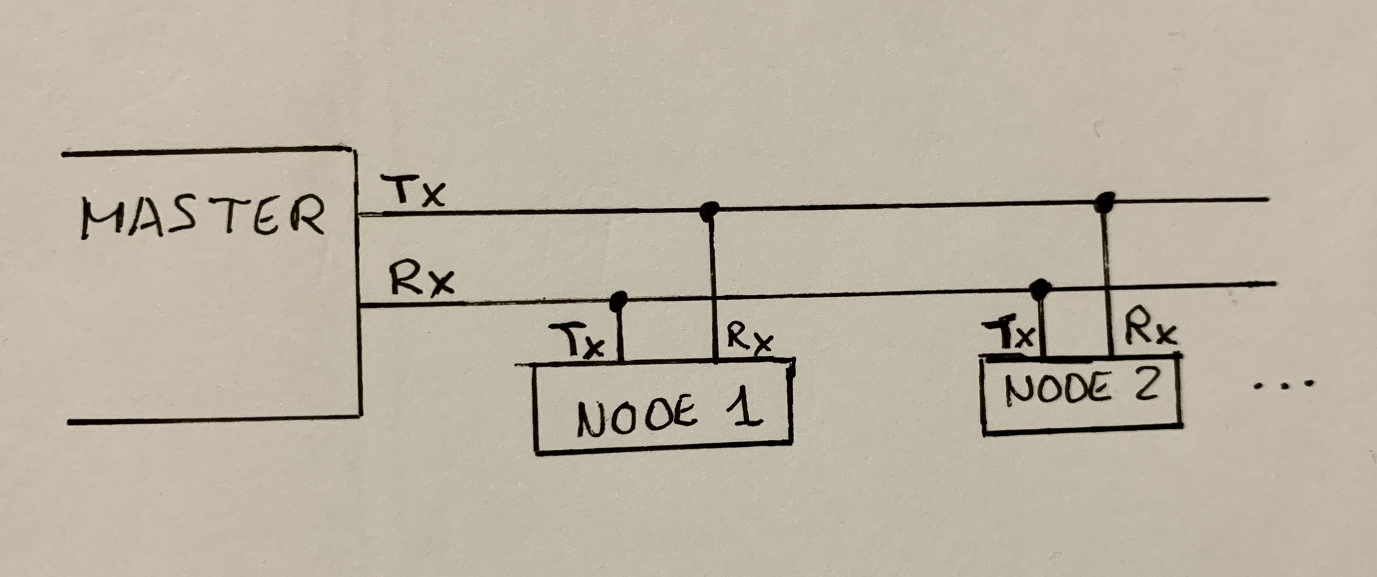
For this assignment I am going to use a cable communication, for this I am going to use the Serial Bus. As Neil explains in class, the serial communication consists of two cables, TX (Transmitter) and RX (Receiver). Through these cables we can send information to other microcontrollers. Update here.
Phototransistor + Servo
To perform serial communication, I will use the boards designed and manufactured in the week of inputs and outputs. In this case, the sensor I use is the phototransistor and the actuator is the servo.
For this I am going to connect the Phototransistor through the FTDI connector, using the TX and RX pins (I had to have placed other pins higher, learned the lesson 😅) and the Servo through the pins that I connected to the Serial Bus. To learn a little more about this form of communication, I am guided by the documentation of Paco Gonzalez de Deusto from 2016 and Elena Cardiel from Fab Lab León of 2019.
- First attempt (It didn't work)
Looking at the documentation, I realize that I have to cross the TX and the RX on one of the two boards. In other words, the TX of the photransistor with the RX of the servo and the RX of the phototransistor with the TX of the servo. Later in the Arduino program, I will use the Software Serial library, to use this library I have to declare which are the TX and RX pins of the ATtiny1614. Going back to my Embedded Programming documentation for the week, the ATtiny1614 uses the TX on pin 5 and the RX on pin 4.
So this would be the connection with my cables.
- Phototransistor (Node).
- Brown-> GND.
- Red -> VCC.
- Orange -> TX.
- Yellow -> RX.
- Servo (Bridge).
- Brown -> GND.
- Red -> VCC.
- Orange -> RX.
- Yellow -> TX.
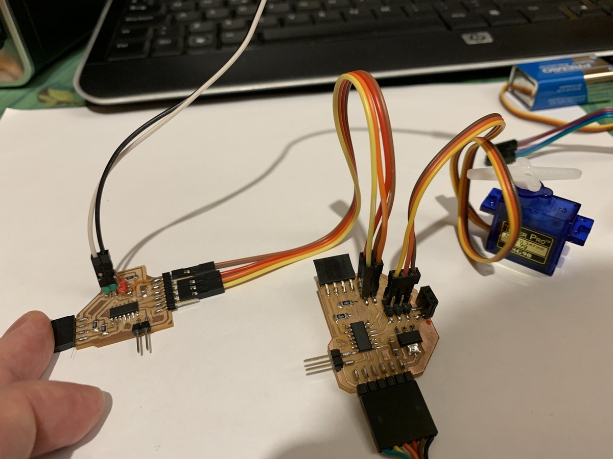
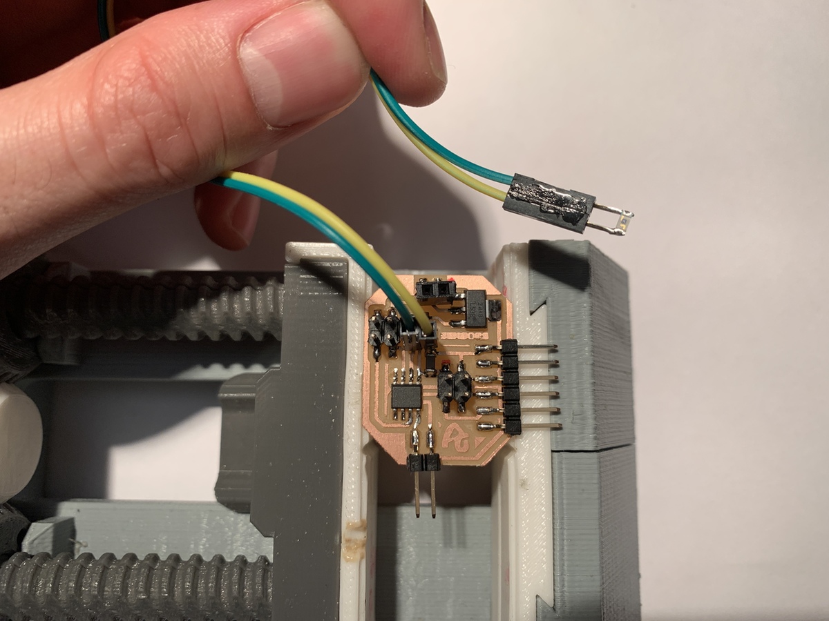
This is the real connection.

Using the Arduino codes of Elena and Paco, I test to see if it works and communicates one board with the other. The servo will move depending on the values that the phototransistor emits.
And it does not work. 😭 The sevo vibrates, but does not move. I check the physical connections, I check the program, changing the speed (from 115200 to 9600, in case a slower speed is necessary), I invert the TX and RX values in the Servo program. Neither.
I speak to my super programming guru and instructor, Pablo Nuñez. We review together the first program, the phototransistor program. I tell him that when I connect it with the FTDI to the computer, no sensor values appear. Weird first thing. For this I use the program that I use in the input week. I also used the Serial.write(); this serves to send binary values (true or false, 0 or 1) does not serve to send ASCI values. For this you have to use the Serial.println().
Once the phototransistor program has been corrected, I check if I have values for the serial via the FTDI and it is correct. I go to the servo program, from the original program I remove the serial.print(), because it is not necessary and can create confusion for the servo. I reload the program to ATtiny1614 and plug the FTDI into the board. The servo continues to vibrate and no data comes through the serial. Pablo asks me how the TX and RX connections are, I tell him they are crossed and he asks me why?
- Second attempt (Works)
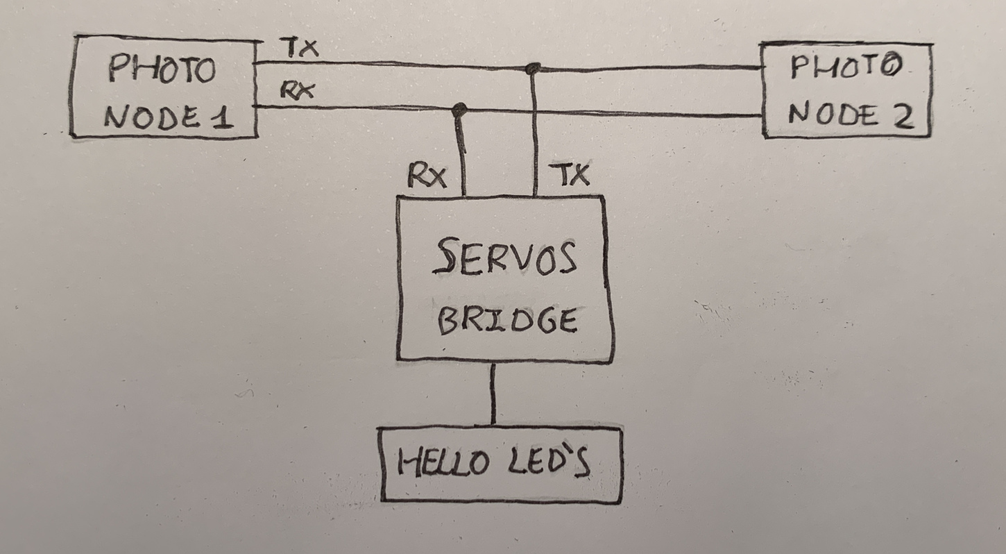
The reason is because I saw that in Paco's scheme he did it this way; and Pablo tells me that being a bus the TX connects to the TX and the RX to the RX. So you can hang as many nodes on the bus as you want, otherwise it would be a point to point. Important: You do not have to cross the TX and RX cables.
In addition, following the assignment of Hugo F. Garcia, IED student of the year 2019, I use the address in the Node with the number 1, so that the Bridge receives it. In the code below it can be seen.
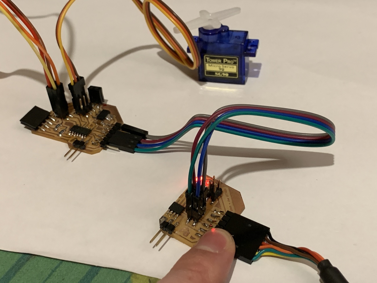
So I connect the cables well and it works. As the light varies a lot, and although the value is mapped, the servo moves a lot, but it works.
This is the correct connection.
- Phototransistor (Node).
- Brown-> GND.
- Red -> VCC.
- Orange -> TX.
- Yellow -> RX.
- Servo (Bridge).
- Brown -> GND.
- Red -> VCC.
- Orange -> TX.
- Yellow -> RX.
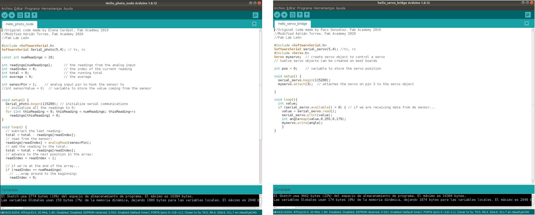
These are the two programs:
Phototransistor Node
//Original code of Adrián Torres. Fab Academy 2020
//Fab Lab León
//ATtiny1614

int sensorPin = 1;    // analog input pin to hook the sensor to
int sensorValue = 0;  // variable to store the value coming from the sensor
int adress = 1;  // addressing number for the bus.

void setup() {
  Serial.begin(115200); // initialize serial communications
}

void loop() {
  sensorValue = analogRead(sensorPin); // read the value from the sensor
  sensorValue = map(sensorValue, 0, 1024, 1024, 0);
  Serial.println(sensorValue); // print value to Serial Monitor
  Serial.print(adress); //ID of the other board
  Serial.print(",");
  Serial.println(sensorValue);
  //mySerial.println("x"); // print value "x" to Serial Monitor
  delay(500); // short delay so we can actually see the numbers

}
Servo Bridge
//Original code made by Paco Gonzalez. Fab Academy 2016 and Hugo F. Garcia. Fab Academy 2019.
//Modified Adrián Torres. Fab Academy 2020
//Fab Lab León
//ATtiny1614

#include
SoftwareSerial serial_servo(5,4); //tx, rx
#include
Servo myservo;  // create servo object to control a servo
// twelve servo objects can be created on most boards

int id, value; // this is going to be the variable that we read.
int MyId = 1; //  variable that we will compare with what comes to us from the bus. The bus will send us a 1.


//int pos = 0;    // variable to store the servo position

void setup() {
  serial_servo.begin(115200);
  myservo.attach(3);  // attaches the servo on pin 3 to the servo object

}

void loop(){
  int value;
   if (serial_servo.available()){
    id = serial_servo.parseInt();
    if (id == MyId){
    value = serial_servo.parseInt();
    }
    else {
    value = 0;
    }
  }
  if (value > 0) { // if we are receiving data from de sensor...
  int angle=map(value,0,1024,0,120); //the servo angle, using the values from 0 to 1024 and from 0 to 120 degrees.
  myservo.write(angle);
  }
}
Phototransistor + Servo + Led's
Once I have managed to communicate two boards, the next spiral development is to connect another board, in this case the Hello Led that I had designed in the week of outputs.
The connection of the wiring will be as follows, continuing with the wiring of the Phototransistor and the Servo, through the FTDI connector I connect the TX and RX to the Bus connector of the Hello LED. For the ATtiny412 the TX and RX pins correspond to 2 and 3 respectively.
In the Arduino program, I configure it to light up the LED when there are values greater than 100 on the Bus. And this is the video. I think it takes a while for the LED to glow because there is too much information on the BUS, or noise.
The Arduino code.
//code made by Adrián Torres
//Fab Academy 2020
//Fab Lab León
//ATtiny412

#include
SoftwareSerial serial_led(2, 3); //tx, rx

int id, value; // this is going to be the variable that we read.
int MyId = 1; //  variable that we will compare with what comes to us from the bus. The bus will send us a 1.

int ledPin1 = 0; //led1


void setup() {
  serial_led.begin(115200);
  pinMode(ledPin1, OUTPUT);

}

void loop(){
   int average;
   if (serial_led.available()){
    id = serial_led.parseInt();
    if (id == MyId){
    average = serial_led.parseInt();
    }
    else {
    average = 0;
    }
  }
    if (average > 100) {
       digitalWrite(ledPin1, HIGH); // led on
    }
    else if (average <= 100) {
      digitalWrite(ledPin1, LOW); // led off
  }
}
Conclusions:
Bus Serial communication becomes a bit complicated if you do not follow the instructions well (problem of crossing the TX, RX cables). But then it seems simple, you send a lot of information on the bus and the Bridge has to manage it. Also try disconnecting the node from the Bridge, and the Bridge does nothing.
For the project, now I have to filter the data of the nodes, and send only with the Serial.write() function a character or a 1 or 0; so there is not so much information on the Bus.
Here is the files to download.
Group Assignment
The week of Interface and Application Programming I was using ESP32 to communicate via wifi with a webserver in different programming languages.
Send a message from my board to the computer
Using the phototransistor board, I will tell you that when the values are less than 20, I will print the message "Train passing" on the screen. It could serve to warn me in my project that a train is coming.
This would be the result.
This would be the Arduino code.
//code made by Adrián Torres
//Fab Academy 2020
//Fab Lab León
//ATtiny1614

#include

int sensorPin = 1;    // analog input pin to hook the sensor to
int sensorValue = 0;  // variable to store the value coming from the sensor

int adress = 1;

void setup() {
  Serial.begin(115200); // initialize serial communications
}

void loop() {
  sensorValue = analogRead(sensorPin); // read the value from the sensor
  sensorValue = map(sensorValue, 0, 1024, 1024, 0);
  if (sensorValue <= 20) {
    Serial.print(adress);
    Serial.print(",");
    Serial.println ("TRAIN PASSING"); //the train is passing.
    delay(500);
    }
}
Here is the files to download.
Littlebits. CloudBit
Nuria told me about the possibility of using LittleBits, since there is a board that allows you to connect to the internet via Wifi and you can send sensor signals or activate actuators.
LittleBits are small electronic modules that join together to create and prototype projects very quickly. The "Poderosas" or the "Jovenes Makers" use them to discover the electronics. Also by its colors you can know if it is power, an input or an output.
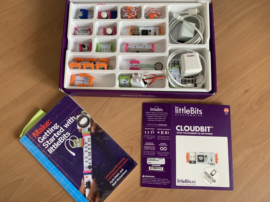
One of the modules is the CloudBit. This module integrates a Wifi module to which we can connect it to a Wifi and interact from the computer or smartphone with the LittleBits.
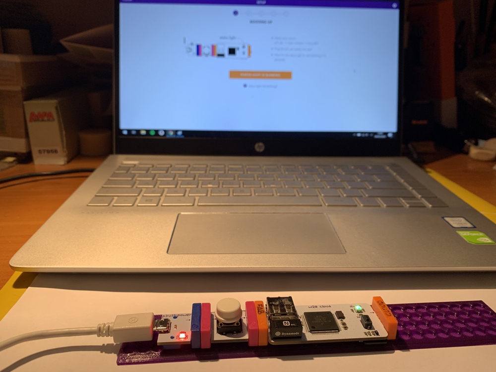
The first thing we do is connect the power, a button and a CloudBit. We open the next page where we create a project, in my case I have called it FABACADEMY.
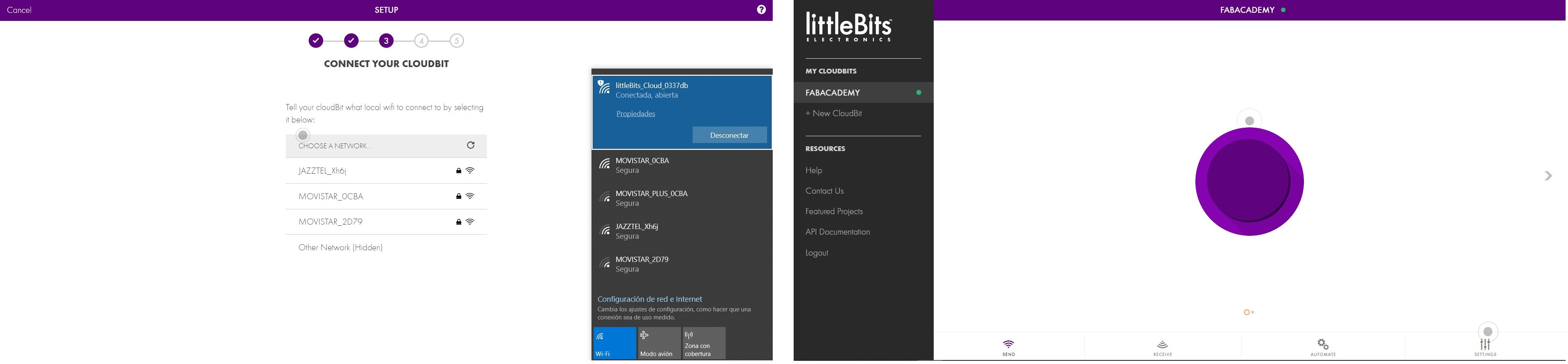
Once we open, we follow the steps that it asks of us. There is a point where we have to connect to the Wifi that the CloudBit creates, and then tell it that Wifi must connect. Once it is connected, we will disconnect from the Wifi of the CloudBit and we will return to the usual Wifi (it will be the same that we use for the Cloudbit). When we have the CloudBit connected to the Wifi, the LED on the board will turn green and the following screen will appear, where we can interact with the different Bits.
Once I have tested that the CloudBit receives and sends information if I press the button, I decide to create an API with the IFTTT platform. IFTTT is a platform that is used for IOT and applications. For example, you receive a sound alert to your CloudBit every time an email arrives. Unfortunately, this union between LittleBits and IFTTT worked very well before, but since the absorption of LittleBits by Sphero there are things that no longer work.
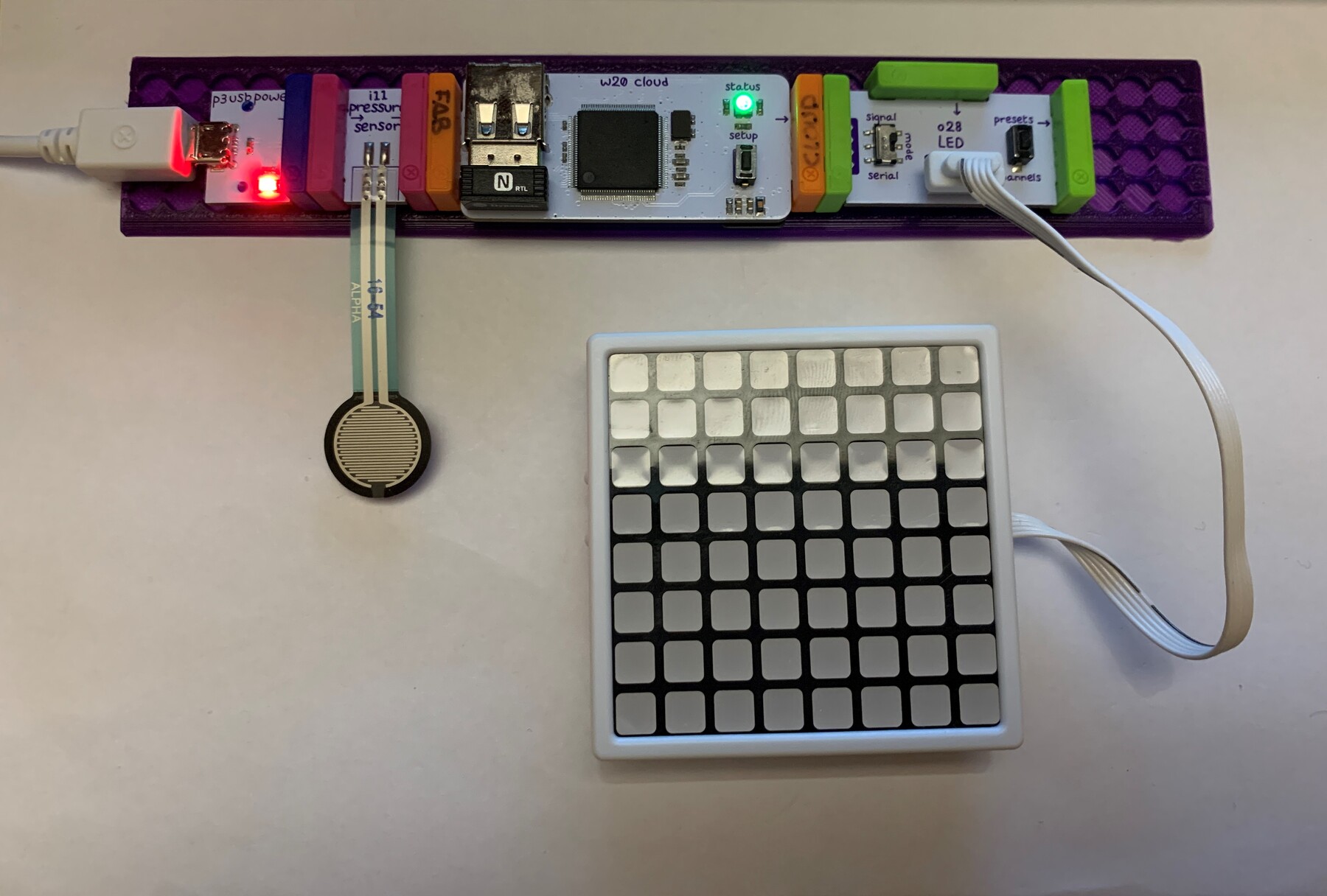
So I can only use LittleBits Cloud Control, which allows me to measure a sensor and run an actuator. In this case I use a pressure sensor and an LED matrix. This is the result. 😍
This is the arrangement of the Bits.
Files
Find below the files that I made for this assignment.
Final Project. Networking.
For my final project I am going to try to use networking to communicate through the Serial Bus two nodes (which are two phototransistors) with a brigde (which is the board with the servos for the barriers). This is my scheme.
After testing the Serial Bus, I decide to use it to communicate my boards in the Final Project. For this I design two new boards.
The first one is an ATtiny412 with a phototransistor. It will be a node, and there will be two boards to detect the passage of the train. I take advantage of the leftover pins of the ATtiny412 to place connectors. As a trick, I frame with yellow paint where the yellow cable (GND) is connected and in the red power connector where the positive of the external power goes. Like the board in the picture, I have made two.
The second is a bridge, which will use an ATtiny1614 to connect the servos of the level crossing barriers. In addition, a digital output will activate the other board that it manufactures for the level crossing lights.
As Plan B, I have placed two connectors for two phototransistors, in case I cannot achieve Networking, that the board serves me for the final project in the same way, by incorporating inputs and outputs.
This would be the connection of the new boards, it is important to check on the flat cable, which are the positions of VCC, GND, TX and RX. For this I paint the VCC pin red.
Now there is the programming part, for me the hardest, I hope to get it. 😅 💪 Working progress...
30/01/2021
Hello Bus with ATtiny 412
During Christmas I decided to design Neil's Hello Bus with the ATtiny412 to be able to update the ATtiny45 as an example. To do this I designed two boards, the Bridge that contains the FTDI to be able to see the values or enter them from the computer and the Node that only receives the information through the Serial Bus.
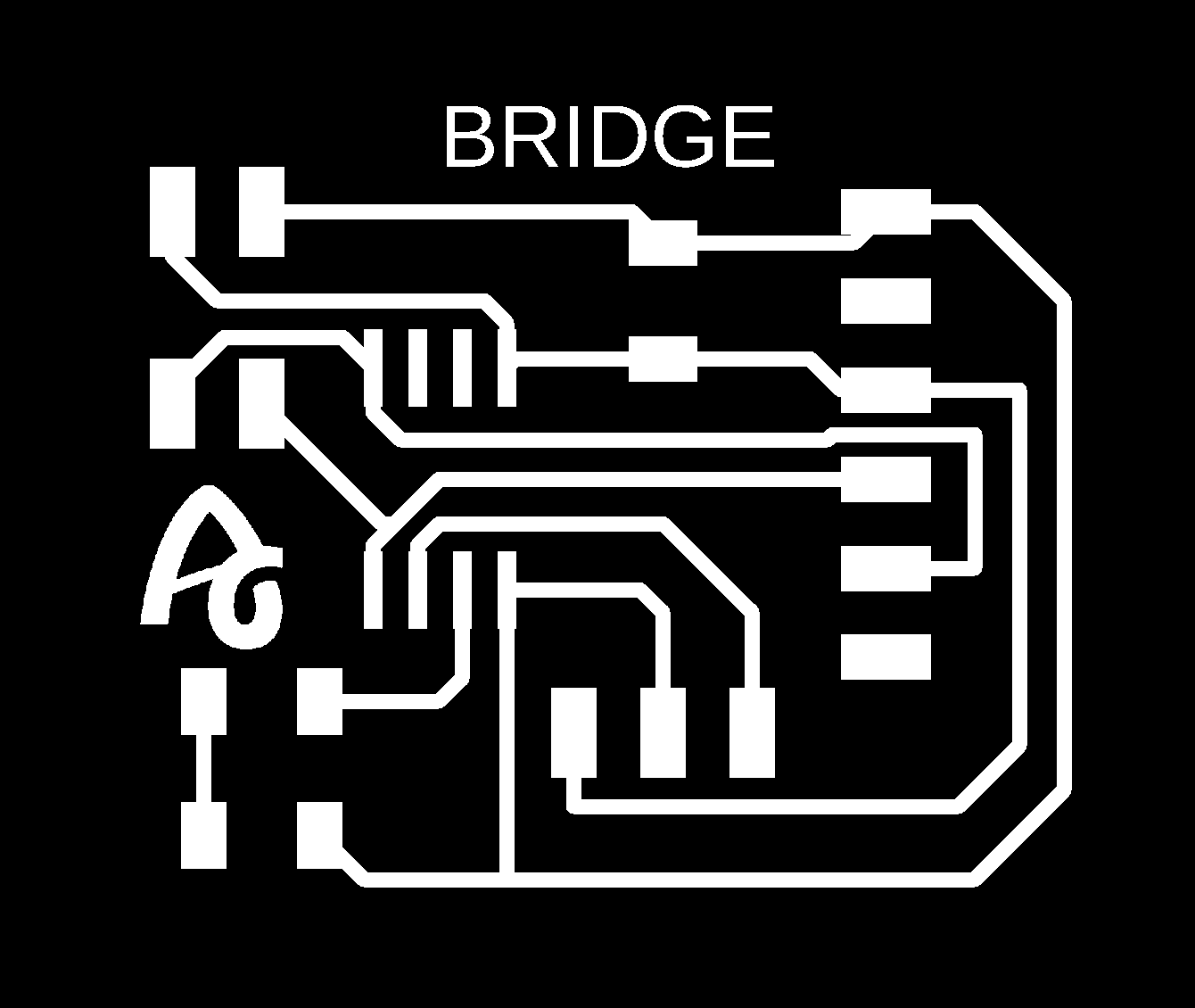
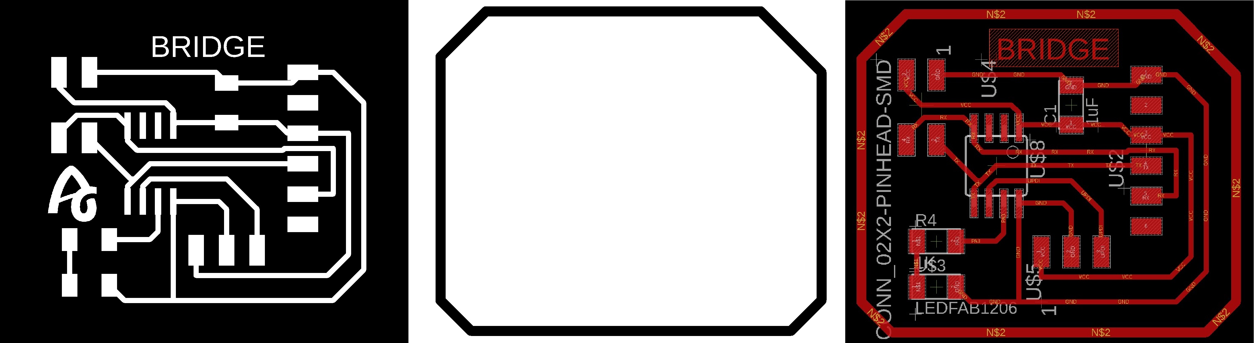
Bridge
This is the design of the Bridge Board. It contains the FTDI, the UPDI + VCC connector (updated), the Bus connector, and an LED on pin PA3 (Arduino pin 4). Here you can find the designs.
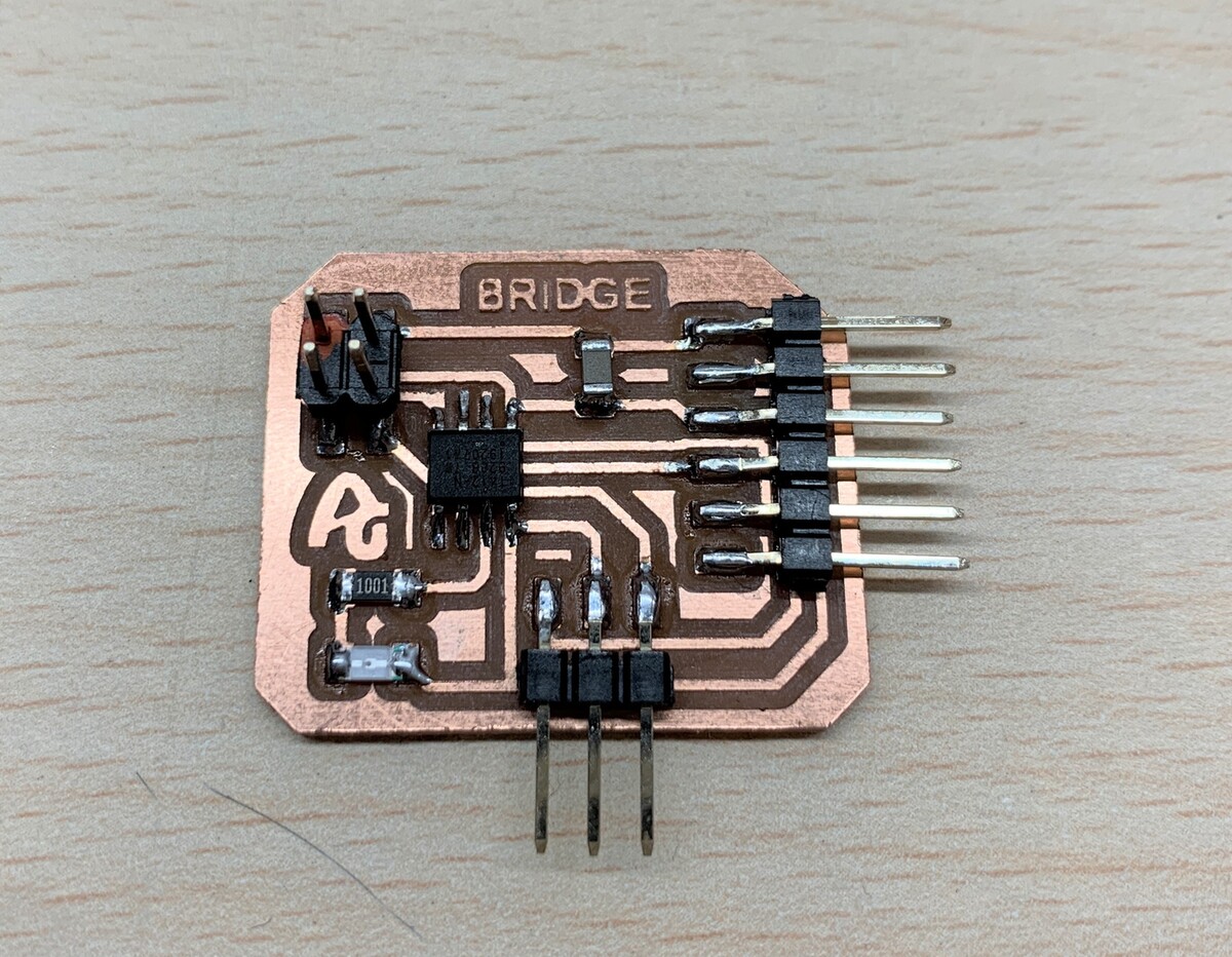
This is the result of the board.
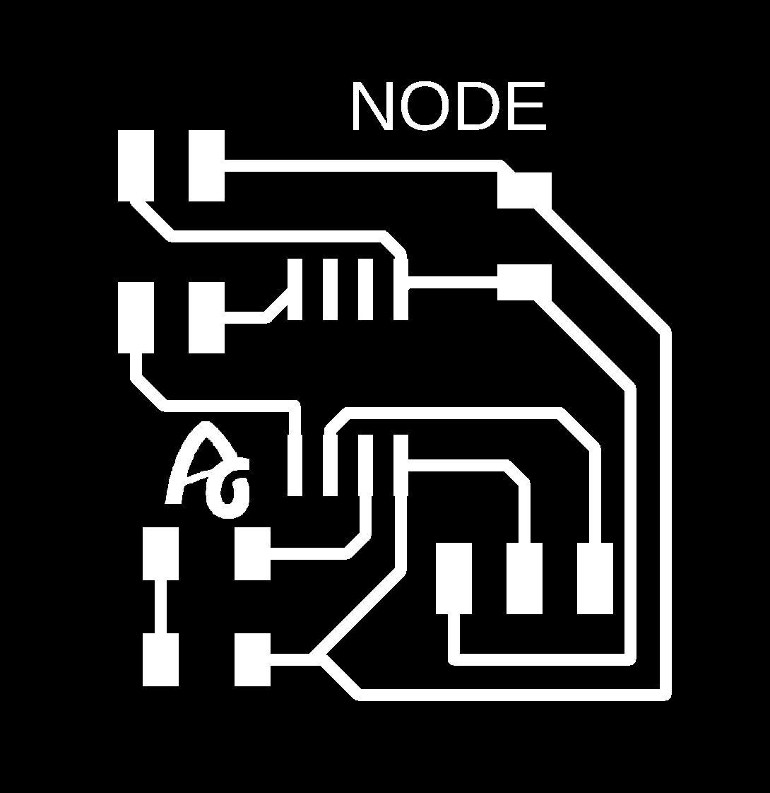
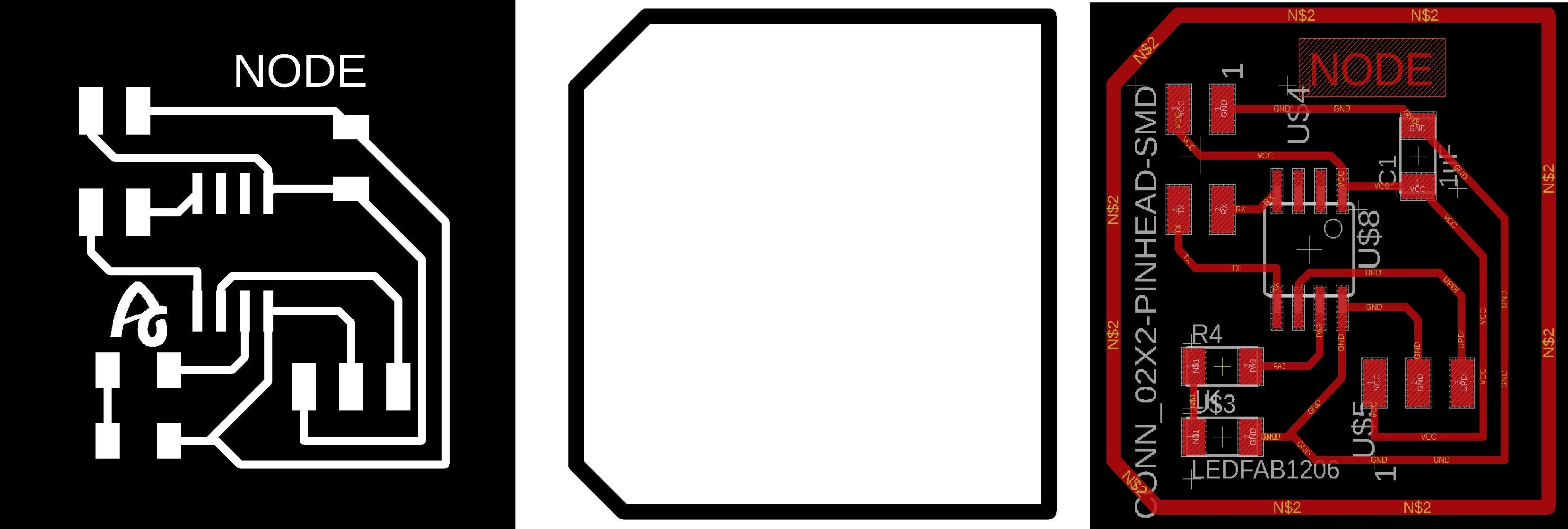
Node
This is the design of the Node Board. You will need at least two boards. It contains the UPDI + VCC connector (updated), the Bus connector, and an LED on pin PA3 (Arduino pin 4). Here you can find the designs.
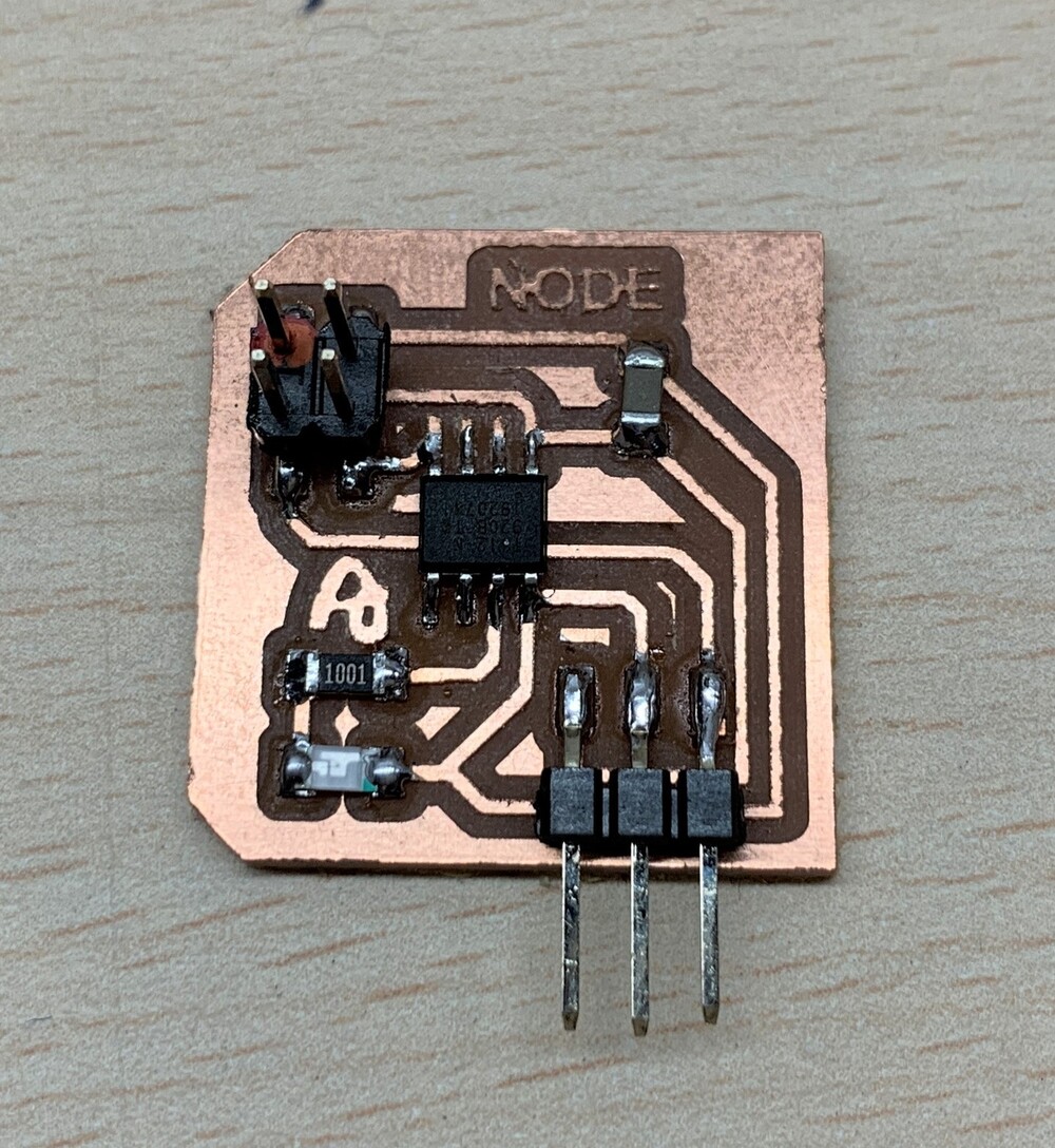
This is the result of the board.
Programming
This would be the Arduino code for the Bridge. The Bridge sends a 0, 1 or 2 through the Serial Bus and, depending on the value, the LED of the corresponding board lights up. Recommendation: Download the program from the link, in the text the symbols <> of the libraries are missing.
//code made by Adrián Torres
//Fab Academy 2020
//Fab Lab León
//ATtiny412 bridge

#include SoftwareSerial.h
SoftwareSerial mySerial(2,3); //RX, TX
int v=0;
int nodeid=1; //Node Identification
int i=0;

void setup() {
  mySerial.begin(115200); //initialize serial communications
  pinMode(4, OUTPUT); // led
}

void loop() {
  for (i=1;i<=3;i++){ // initialization; condition; increment
  mySerial.println(i); // print value to Serial
  delay(1000);
  }

  while (mySerial.available () == 0 ) {}  //while serial is 0
  v = mySerial.parseInt();
  if(v == nodeid)        //If the value of v equals the identification of the node
{
  digitalWrite(4,HIGH);
  delay(200);
  digitalWrite(4,LOW);
  delay(200);
}
else
{
  digitalWrite(4,LOW);
 }
}
Here is the file to download.
If you want to send values through the Serial Monitor, we must use the following code. Recommendation: Download the program from the link, in the text the symbols <> of the libraries are missing.
//code made by Adrián Torres
//Fab Academy 2020
//Fab Lab León
//ATtiny412 bridge

int v=0;
int nodeid=1; //Node Identification

void setup() {
  Serial.begin(115200); //initialize serial communications
  pinMode(4, OUTPUT); //led
}

void loop() {
  while (Serial.available () == 0 ) {}
  v = Serial.parseInt();
  Serial.println(v);

  if(v == nodeid)   //If the value of v equals the identification of the node
{
  digitalWrite(4,HIGH);
  delay(1000);
  digitalWrite(4,LOW);
  delay(1000);
}
else
{
  digitalWrite(4,LOW);
 }
}
Here is the file to download.
This would be the Arduino code for the Nodes. IMPORTANT: We must assign a number to each node. Recommendation: Download the program from the link, in the text the symbols <> of the libraries are missing.
//code made by Adrián Torres
//Fab Academy 2020
//Fab Lab León
//ATtiny412 node 1

#include SoftwareSerial.h
SoftwareSerial mySerial(2,3); //RX, TX
int v=0;
int nodeid=2;//Node Identification

void setup() {
  mySerial.begin(115200); //initialize serial communications
  pinMode(4, OUTPUT); // led
}

void loop() {
  while (mySerial.available () == 0 ) {} //while serial is 0
  v = mySerial.parseInt();
  mySerial.println(v);
  if(v == nodeid)     //If the value of v equals the identification of the node
{
  digitalWrite(4,HIGH);
  delay(200);
  digitalWrite(4,LOW);
  delay(200);
}
else
{
  digitalWrite(4,LOW);
 }
}
Here is the files to download.
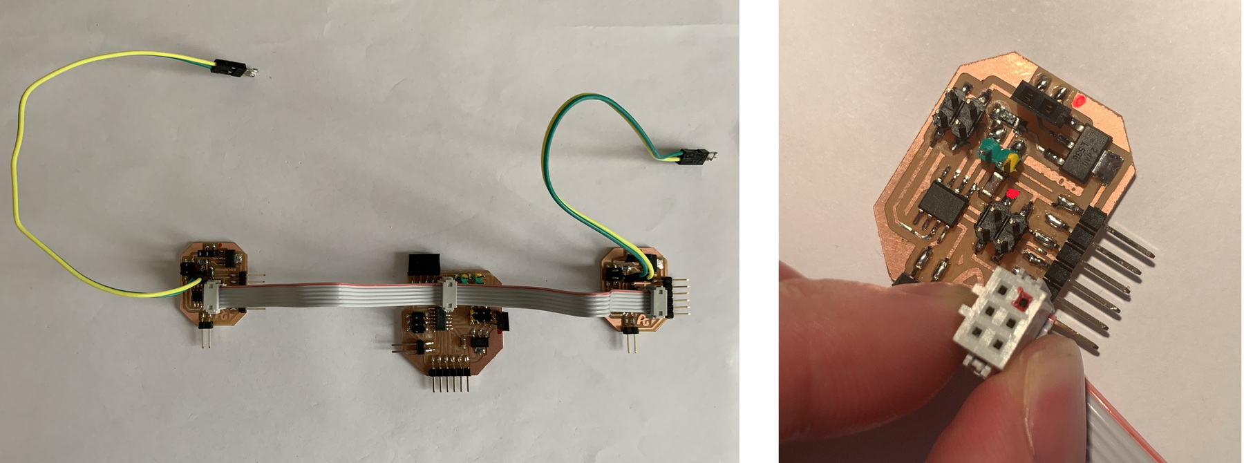
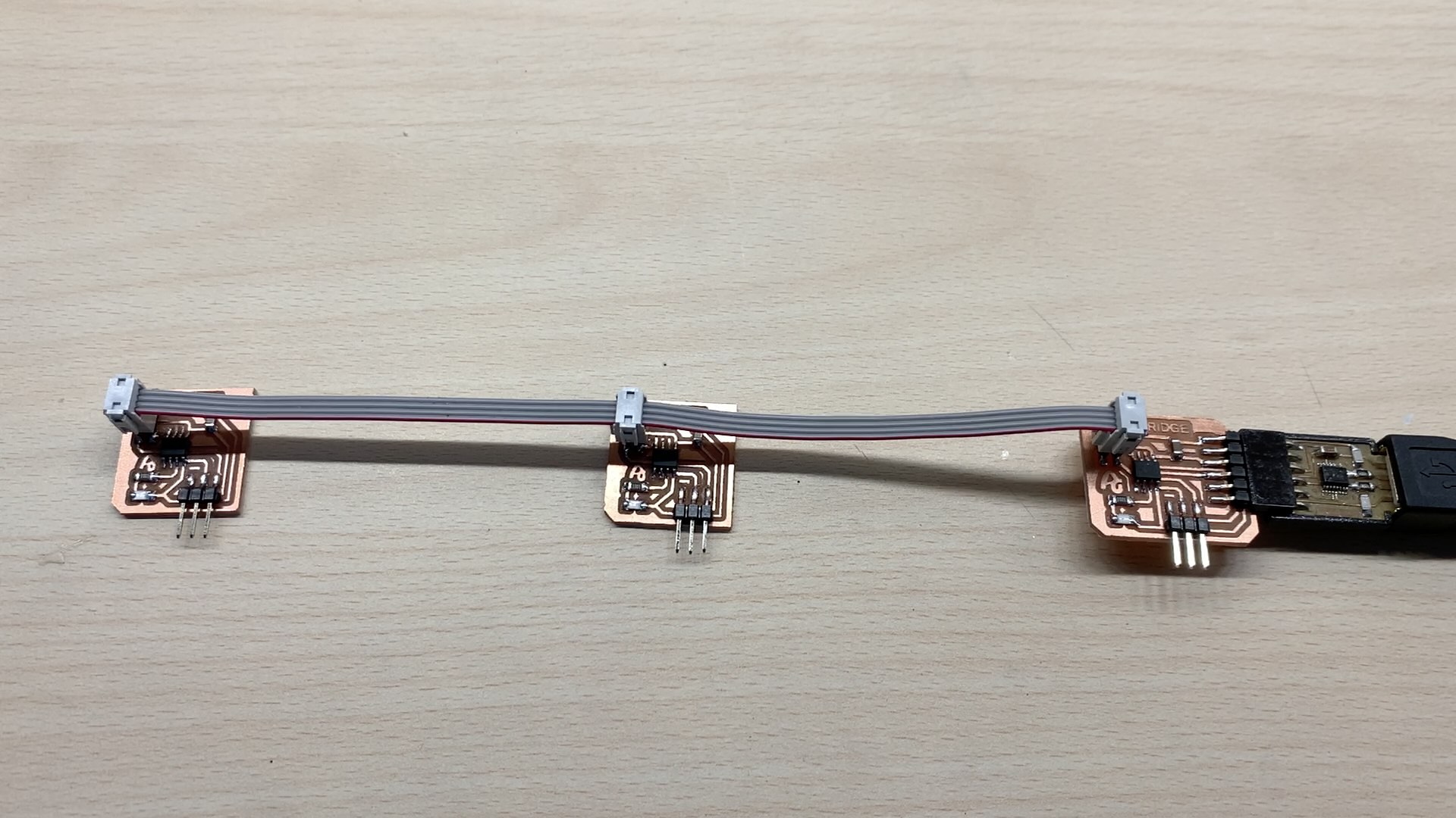
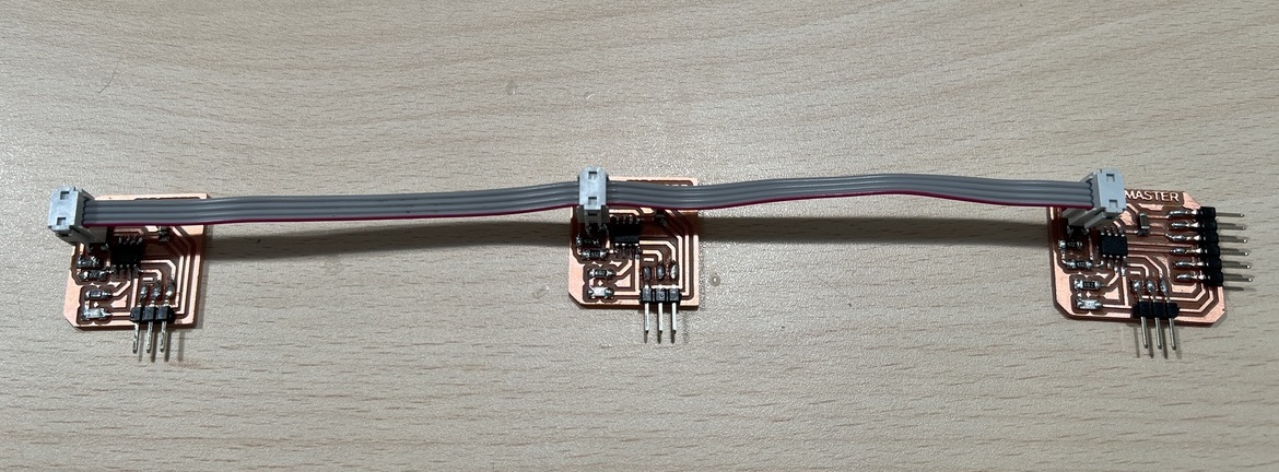
Connection and Operation
Using a 4-wire flat cable and the connectors we connect the three boards. Here the video of the operation. The Bridge sends a 1, 2 or 3 through the Serial Bus and, depending on the value, the LED of the corresponding board lights up.
24/07/2022
Hello I2C with ATtiny 412
After finishing the course, and thanks to one of the Fab Lab León students, Luis Diaz, I wanted to try and learn how I2C communications works. For this I designed two boards, the Master that contains the FTDI to be able to see the values or enter them from the computer and the Node that only receives the information through the I2C.
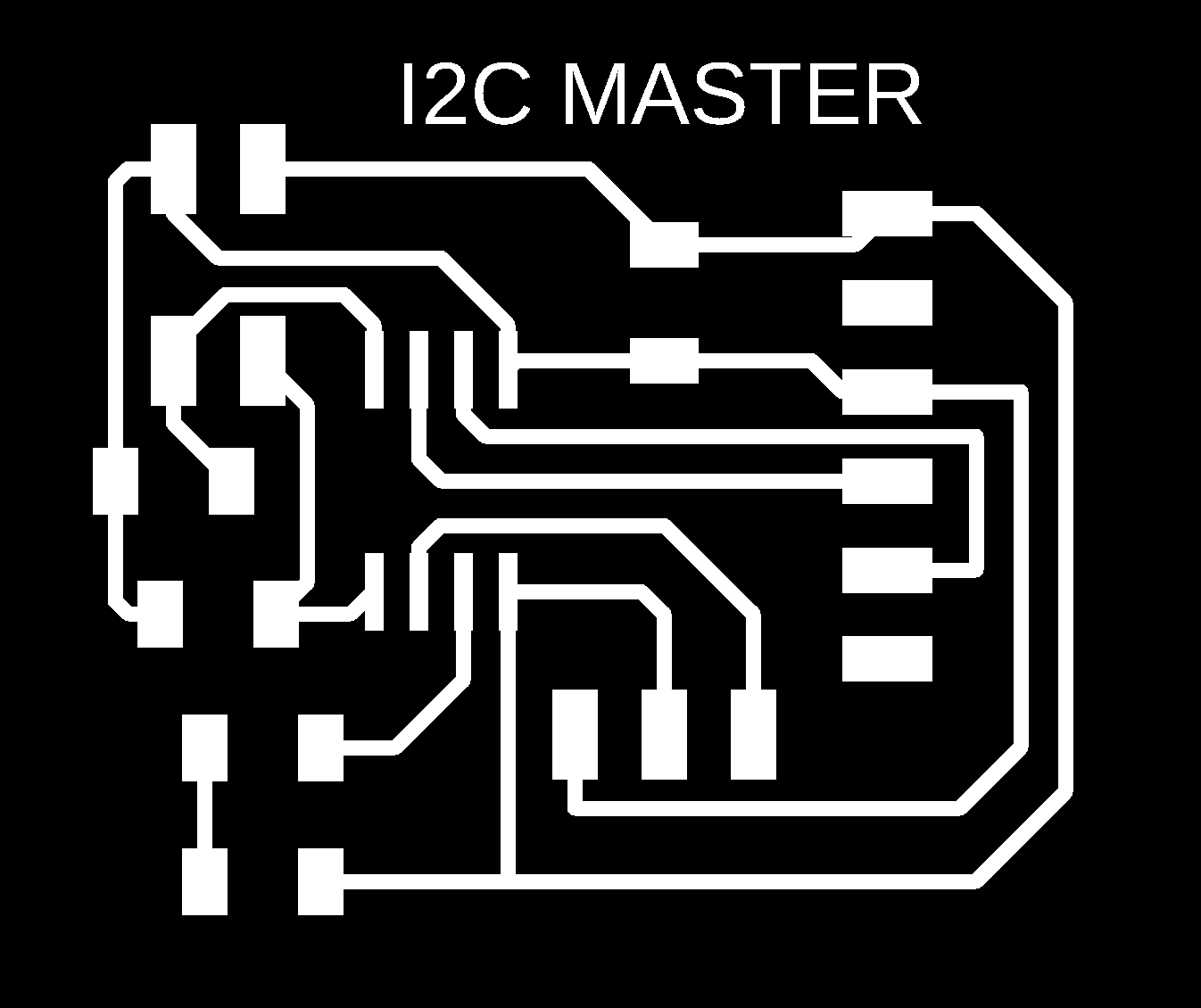
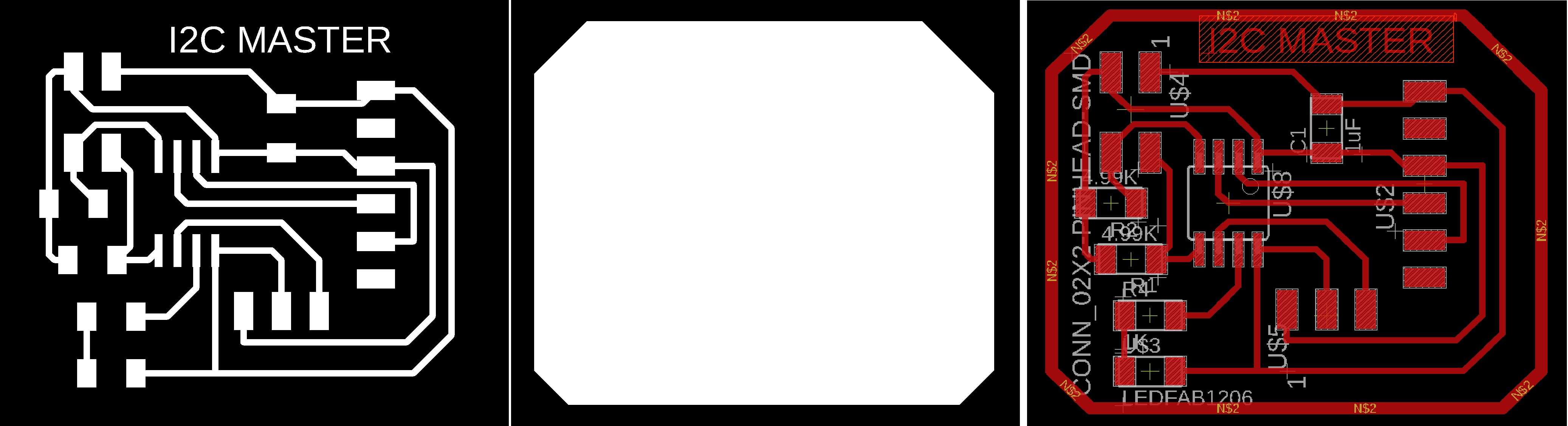
Master
This is the design of the Master Board. It contains the FTDI, the UPDI + VCC connector (updated), the I2C connector with the two 4.7k pull-up resistors, and an LED on pin PA3 (Arduino pin 4). Here you can find the designs.
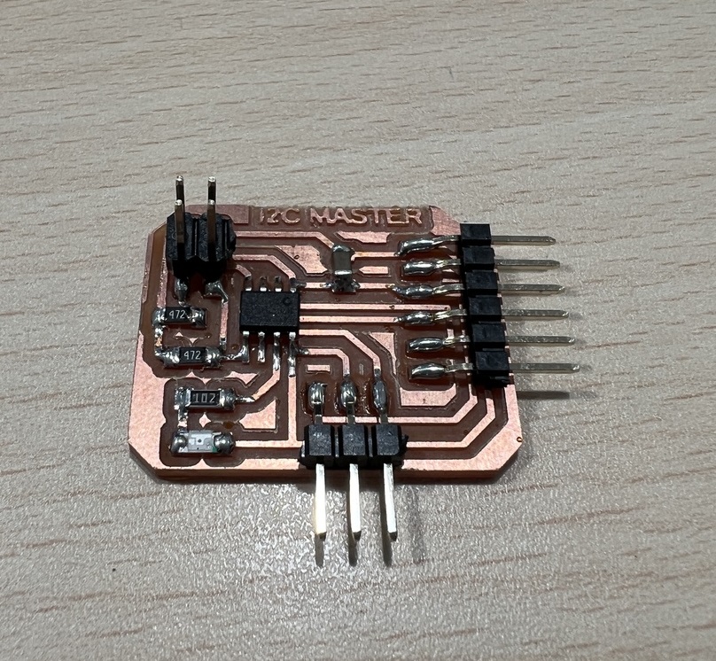
This is the result of the board.
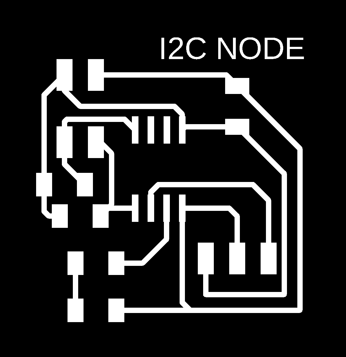
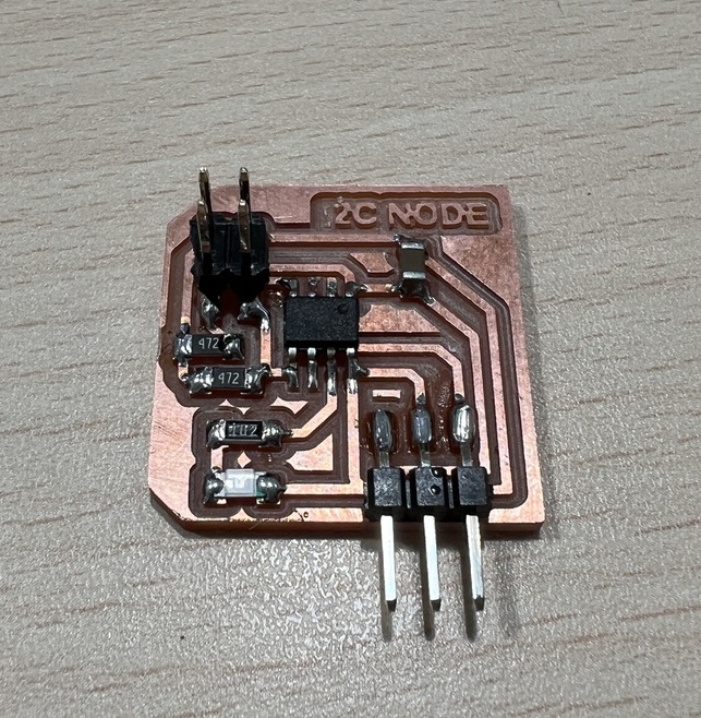
Node
This is the design of the Node Board. You will need at least two boards. It contains the UPDI + VCC connector (updated), the I2C connector with the two 4.7k pull-up resistors, and an LED on pin PA3 (Arduino pin 4). Here you can find the designs.
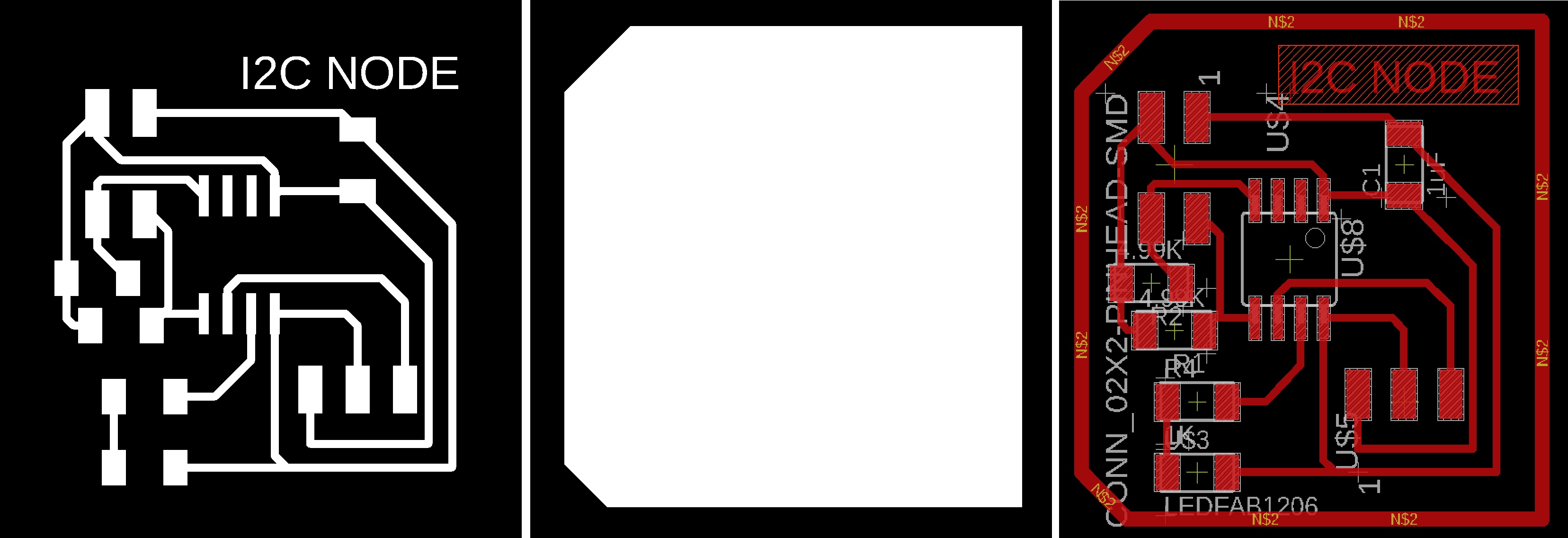
This is the result of the board.
Programming
This would be the Arduino code for the Master. The Master sends a 0, 1, 2 or 3 through the I2C and, depending on the value, the LED of the corresponding board lights up. Recommendation: Download the program from the link, in the text the symbols <> of the libraries are missing.
//original code by Luis Diaz_ Hola
//Fab Academy 2022
//Fab Lab León
//ATtiny412 master I2C

#include

int i = 0;
int j = 0;

int led = 4; //led pin

void setup() {
  Serial.begin(115200); //speed of the communications
  Wire.begin();

  pinMode(led, OUTPUT); // led
}

void loop()
{

  for (i = 0; i <= 3; i++) { // 0,1,2,3

    Wire.beginTransmission(8); //slave number 8
    if ( i == 1) {
      Wire.write(1);
      Serial.println("1");
    } else {
      Wire.write(0);
      Serial.println("0");
    }
    Wire.endTransmission();

    Wire.beginTransmission(9); //slave number 9
    if ( i == 2) {
      Wire.write(1);
      Serial.println("1");
    } else {
      Wire.write(0);
      Serial.println("0");
    }
    Wire.endTransmission();

    for (j = 0; j <= i; j++) { // blink i times
      digitalWrite(led, HIGH);
      delay(200);
      digitalWrite(led, LOW);
      delay(200);
    }

    delay(1000);
  }

}
Here is the file to download.
This would be the Arduino code for the Nodes. IMPORTANT: We must assign a number to each node. Recommendation: Download the program from the link, in the text the symbols <> of the libraries are missing.
//original code by Luis Diaz
//Fab Academy 2022
//Fab Lab León
//ATtiny412 node 1 I2C

#include
int d1 = 0;
#define led 4

void setup() {
  pinMode(led, OUTPUT);
  Serial.begin(115200);
  Wire.begin(8);     //change address for the nodes in my case I use 8 and 9.
  Wire.onReceive(recieveEvent);
}

void loop() {
  if (d1 == 1)
  {
    digitalWrite(led, HIGH);
  }
  else
  {
    digitalWrite(led, LOW);
  }

  delay(500);
}

void recieveEvent(int howMany)
{
  while (Wire.available())
  {
    d1 = Wire.read();
  }
}
Here is the files to download.
Connection and Operation
Using a 4-wire flat cable and the connectors we connect the three boards. Here the video of the operation. The Master sends a 0, 1, 2 or 3 through the I2C and, depending on the value, the LED of the corresponding board lights up.
Files
Find below the files that I made for the final project.