
Week 08. Embedded Programming
Like the previous week, there are two types of assignments, one group and one individual. In my case being alone in the Fab Lab, I do both.
- Compare the performance and development workflows for different microcontroller families. ✔
- Document your work (in a group or individually). ✔
- Read the datasheet for the microcontroller you are programming. ✔
- Program the board you have made to do something, with as many different programming languages and programming environments as possible. ✔
- Linked to the group assignment page. ✔
- Documented what you learned from reading a microcontroller datasheet. ✔
- Programmed your board. ✔
- Described the programming process/es you used. ✔
- Included your source code. ✔
- Included a short ‘hero video’ of your board. ✔
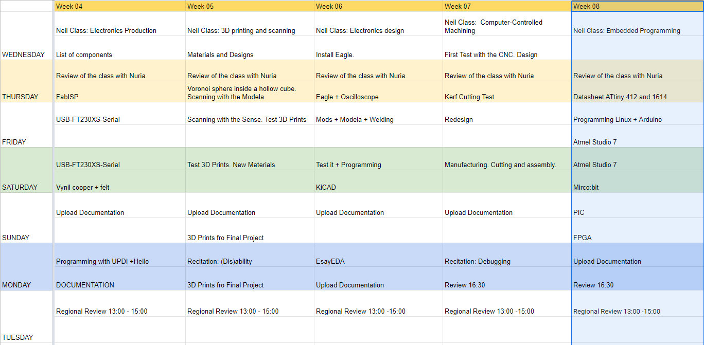
Like every week, my weekly schedule. 😊
Well, the coronavirus arrived in Spain and it is time to be locked up at home by quarantine. Fortunately, I took all the boards and devices I needed for this assignment. Stay at home. 😷
Group Assignment
The Group Assignment page is at the following link.
If you click on this link, you go to the Group Assignment section that I have done for this week.
Datasheet: ATtiny412 and ATtiny1614
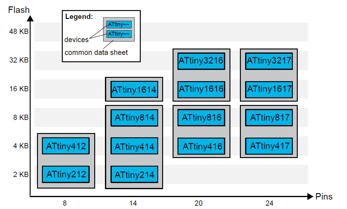
Within the tinyAVR-1series family there are several models, the ones I am using at the Fab Academy are the ATtiny 412 and the ATtiny 1614. One of their differences is memory, as we can see in the following graph which is taken from the Datasheet.
ATtiny412
This little microcontroller with only 8 pins has a lot to offer us:
- 8 pin package.
- Two internal clocks 16 and 20 MHz.
- 4 KB Flash Memory.
- 128 B EEPROM.
- 256 B SRAM.
- Maximum voltage: 6V; minimum voltage -0.5 V.
After looking at the basic features, you will find the pinning of the microcontroller. I combine the Datasheet image with the one from the SpenceKonde website on the ATtiny412.
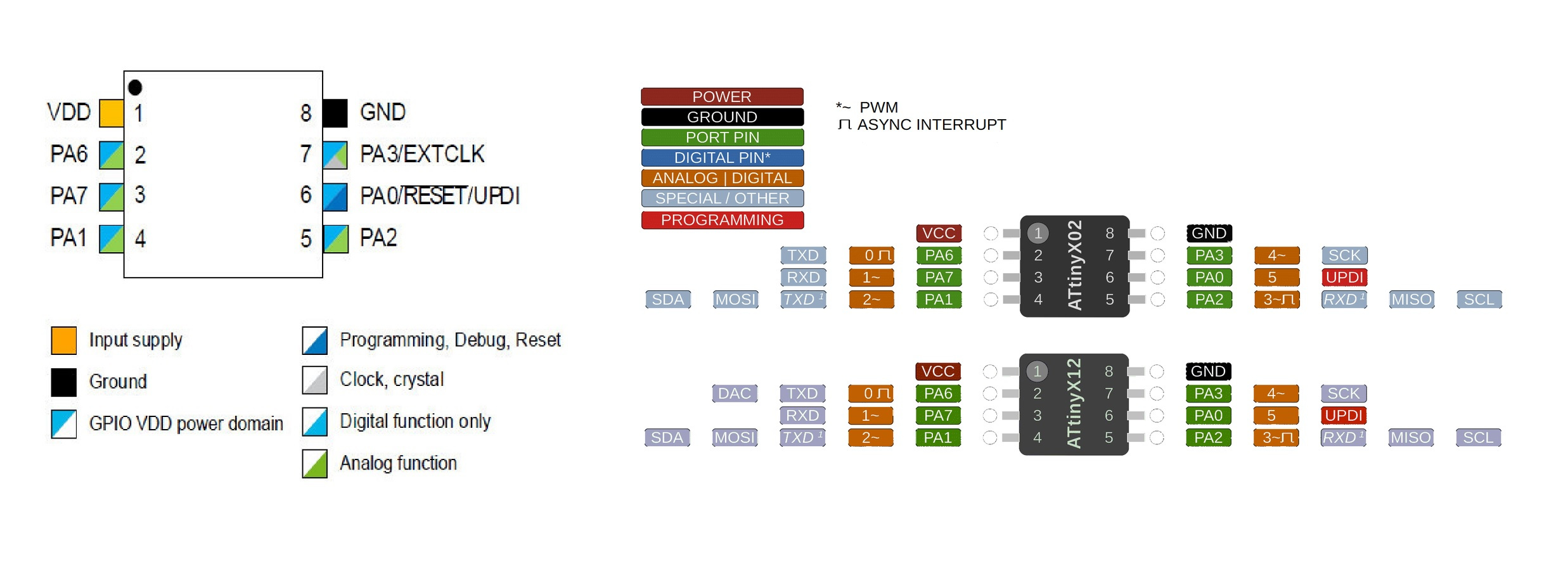
- VDD: Supply voltage.
- GND: Ground.
- Digital pins: PA0, PA1, PA2, PA3, PA4, PA5, PA6.
- Analog pins: PA1, PA2, PA3, PA4, PA5, PA6.
- UPDI Programming pin: PA0 (physical pin number 6).
- External Clock Pin: PA3.
All I/O pins can be configured with internal pullup resistance.
Within the communications section there are different types and their pins are different. It is clear that the different communication protocols cannot all be used at the same time, because they have pins in common.
- USART - Universal Synchronous and Asynchronous Receiver and Transmitter: It has the RX (PA1) and the TX (PA2).
- SPI - Serial Peripheral Interface: It has only MOSI (PA1), MISO (PA2) and SCK (PA3).
- TWI - Two Wire Interface (I2C): It has SDA (PA1) and SCL (PA2).
Another important thing that the datasheet is telling us is that you have to keep in mind which kind of input component you are using, digital or analog: for instance, if you are using a temperature sensor (analog component) you have to connect it to an ACD (analog to digital converter) port otherwise the microcontroller isn't able to transform the information that is receiving from the sensor to a digital data.
ATtiny1614
As we have looked at the graph, there are more microcontrollers within the tinyAVR-1series family. Another ATtiny I use is the 1614. I combine the Datasheet image with the one from the SpenceKonde website on the ATtiny1614.
- 14 pin package.
- Two internal clocks 16 and 20 MHz.
- 16 KB Flash Memory.
- 256 B EEPROM.
- 2 KB SRAM.
- Maximum voltage: 6V; minimum voltage -0.5 V.
After looking at the basic features, you will find the pinning of the microcontroller.
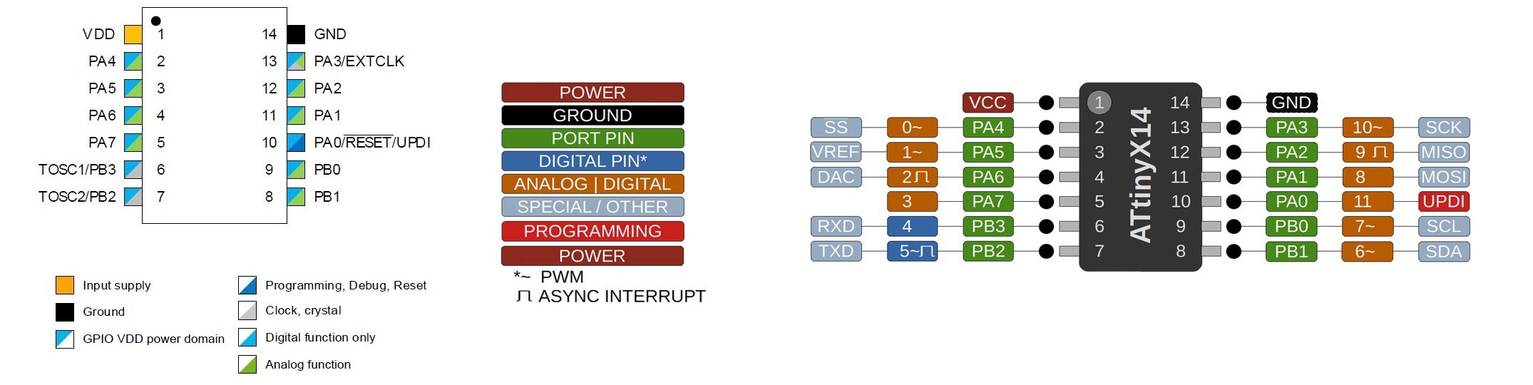
- VDD: Supply voltage.
- GND: Ground.
- Digital pins: Port A: PA0, PA1, PA2, PA3, PA4, PA5, PA6, PA7. Port B: PB0, PB1, PB2, PB3.
- Analog pins: PA1, PA2, PA3, PA4, PA5, PA6, PA7. Port B: PB0, PB1.
- UPDI Programming pin: PA0 (physical pin number 10).
- External Clock Pin: PA3.
All I/O pins can be configured with internal pullup resistance.
Within the communications section there are different types and their pins are different. It is clear that the different communication protocols cannot all be used at the same time, because they have pins in common.
- USART - Universal Synchronous and Asynchronous Receiver and Transmitter: It has the RX (PB2 or PA2) and the TX (PB3 or PA1).
- SPI - Serial Peripheral Interface: It has only MOSI (PA1), MISO (PA2), SCK (PA3), SS (PA4) .
- TWI - Two Wire Interface (I2C): It has SDA (PB1 or PA1) and SCL (PB0 or PA2).
Another important thing that the datasheet is telling us is that you have to keep in mind which kind of input component you are using, digital or analog: for instance, if you are using a temperature sensor (analog component) you have to connect it to an ACD (analog to digital converter) port otherwise the microcontroller isn't able to transform the information that is receiving from the sensor to a digital data.
29/03/2020
ATtiny3216
Since last week I looked at the datsheet of the other microcontrollers, this time it's time to look at everyone's "big brother", the ATtiny3216.. I combine the Datasheet image with the one from the SpenceKonde website on the ATtiny3216.
- 20 pin package.
- Internal clocks 1/4/5/8/10/16 20 MHz.
- 32768 bytes Flash Memory.
- 256 bytes EEPROM.
- 2048 bytes SRAM.
- Maximum voltage: 6V; minimum voltage -0.5 V.
After looking at the basic features, you will find the pinning of the microcontroller.
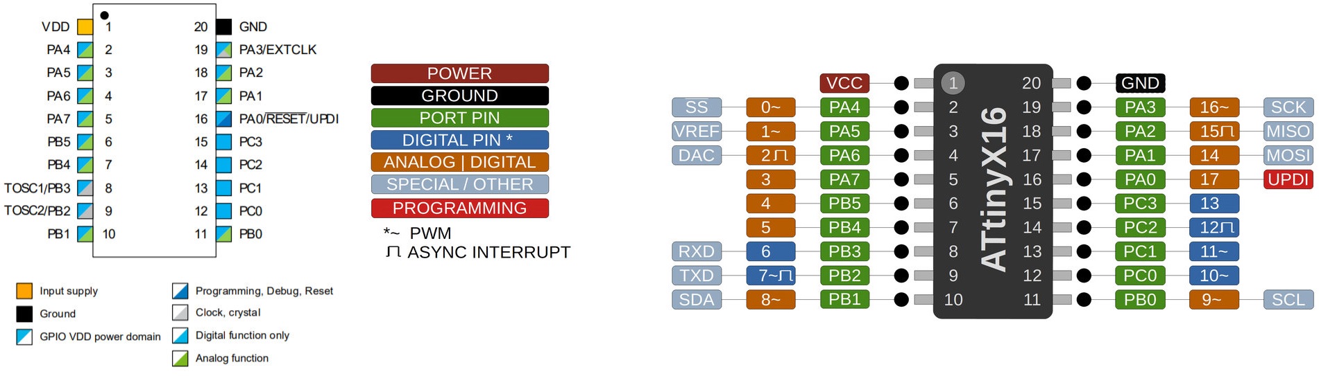
- VDD: Supply voltage.
- GND: Ground.
- Digital pins: Port A: PA0, PA1, PA2, PA3, PA4, PA5, PA6, PA7. Port B: PB0, PB1, PB2, PB3, PB4, PB5. Port C: PC0, PC1, PC2, PC3.
- Analog pins: Port A: PA0, PA1, PA2, PA3, PA4, PA5, PA6, PA7. Port B: PB0, PB1, PB4, PB5.
- UPDI Programming pin: PA0 (physical pin number 16).
All I/O pins can be configured with internal pullup resistance.
Within the communications section there are different types and their pins are different. It is clear that the different communication protocols cannot all be used at the same time, because they have pins in common.
- USART - Universal Synchronous and Asynchronous Receiver and Transmitter: It has the RX (PB3 or PA2) and the TX (PB2 or PA1).
- SPI - Serial Peripheral Interface: It has only MOSI (PA1 or PC2), MISO (PA2 or PC1), SCK (PA3 or PC0), SS (PA4 or PC3) .
- TWI - Two Wire Interface (I2C): It has SDA (PB1 or PA1) and SCL (PB0 or PA2).
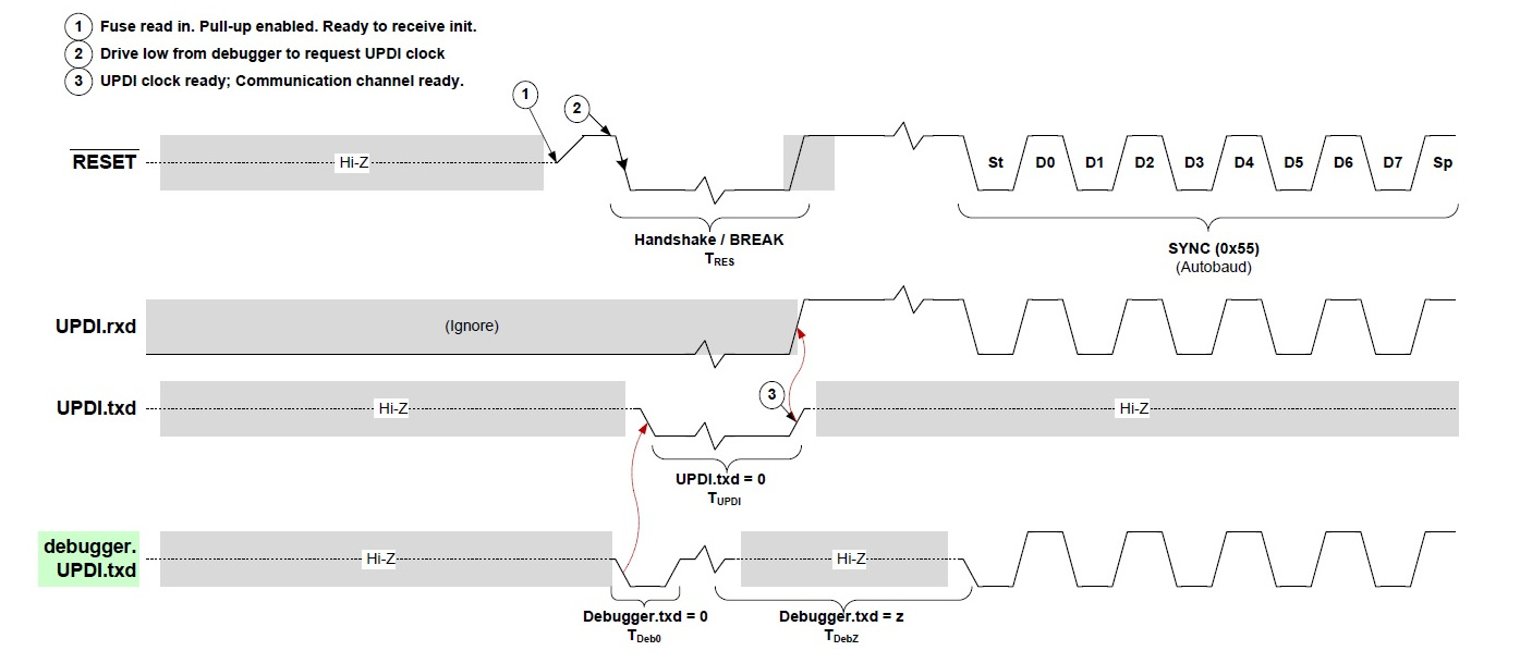
UPDI - Unified Program and Debug Interface
To program these two microcontrollers, only one cable and GND are necessary. Here is the process, for some reason it takes so long to load the programs. 😅
Programming
Linux + Arduino + PyUPDI
ATtiny1614
I follow the tutorial that Pablo taught me that they used in the Bootcamp in India that Santi from Fab Lab BCN created.
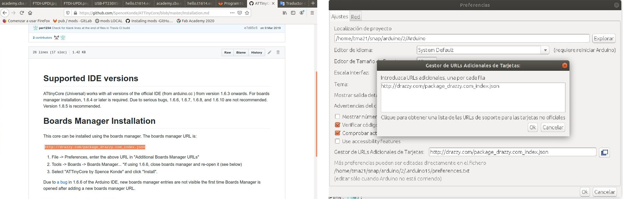
- 1. For this I install Arduino. Within Arduino, in the preferences tab we will add the URL to load the Arduino IDE with other cards or microcontrollers. Spence Konde tutorial
- 2. I download "pyupdi".
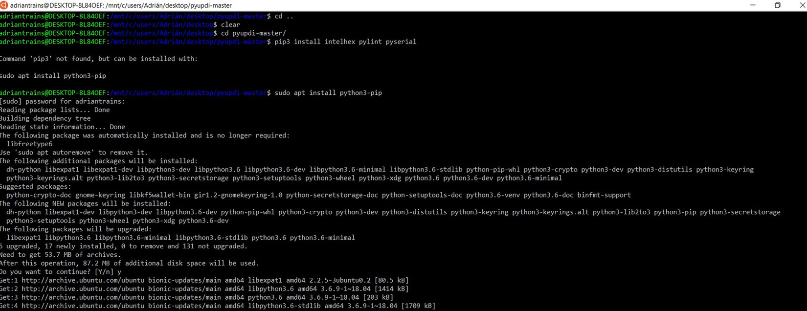
- 3. Open terminal. Install dependeces: pip3 install intelhex pylint pyserial (I have had to install it on my Ubuntu LTS and do screenshot, because I did not do it when I was working on the computer with Linux.) 😪
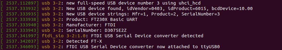
- 4. I connect the USB-FTDI.
- 5. I run dmesg -w
- 6. Connect and disconet the ftdi cable and take note of the "port name" where:
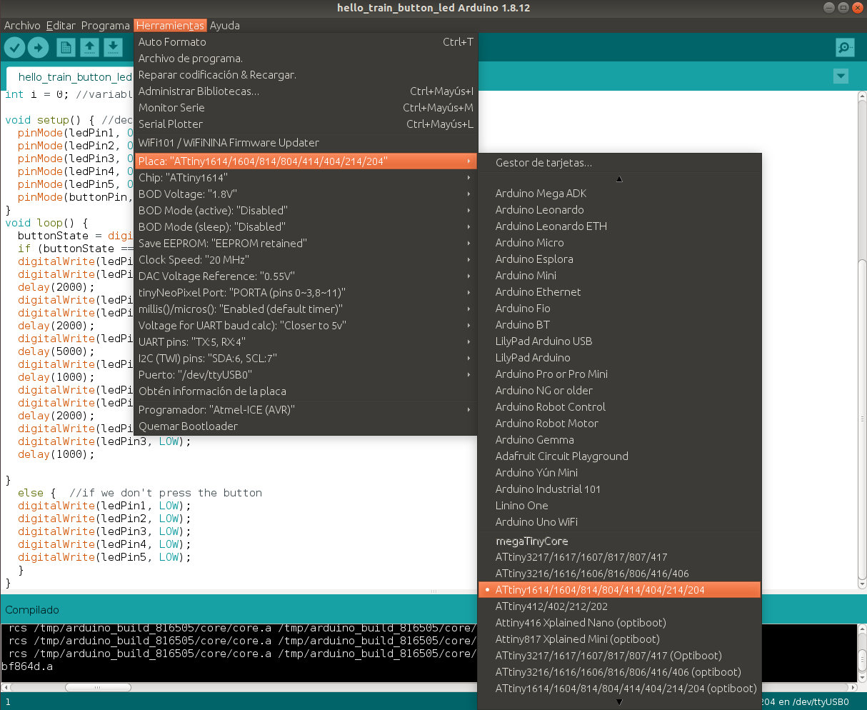
- 7. I configure the Arduino IDE for the ATtiny 1614; I configure the clock to 20MHz, the TX and RX ports and in my case the communication port with the /dev/ttyUSB0 microcontroller.
- 8. Only the code is compiled. In the Arduino IDE dialog box, we will see where the temporary files are located.
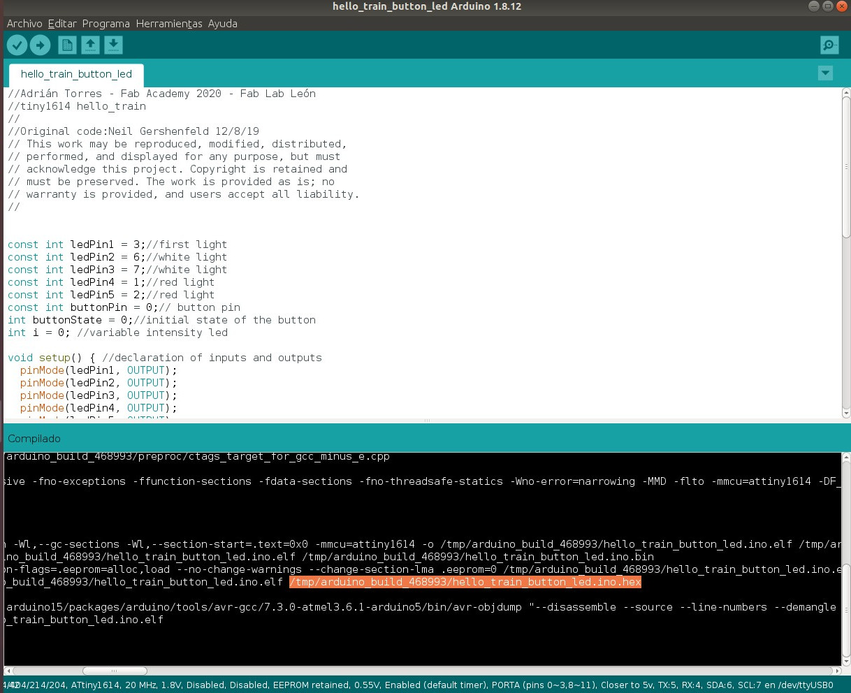
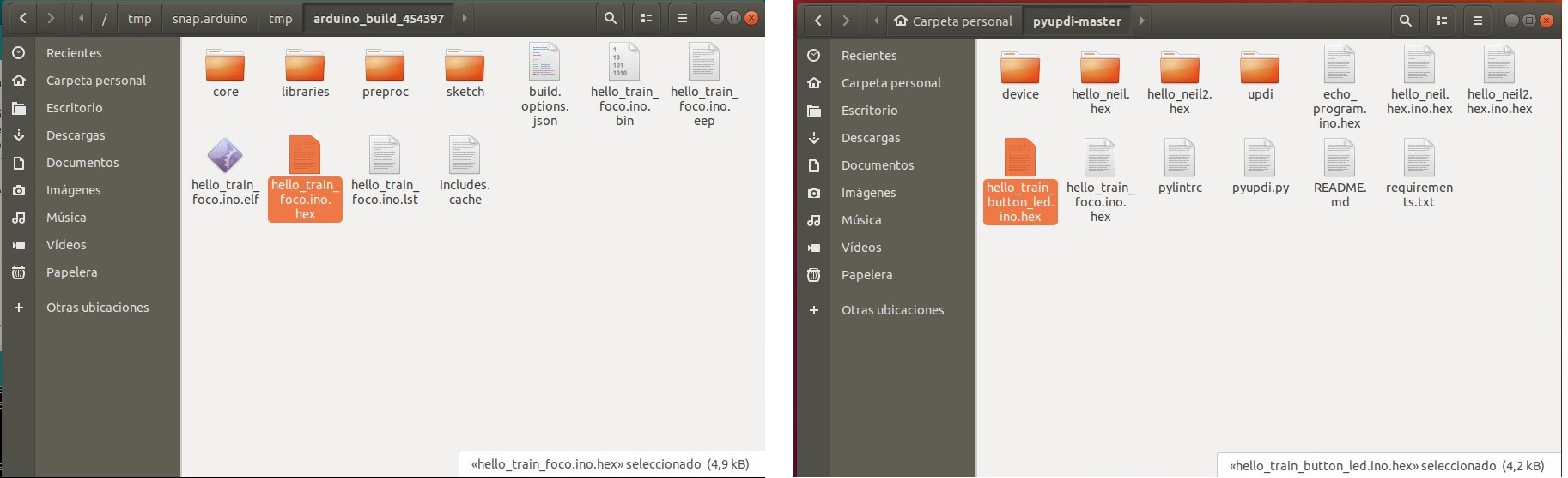
- 9. We look for the .hex file which is the one we need, it is in a temporary folder. Once located, we copy it and paste it in the pyupdi folder.
- 10. I connect it as follows. USB-Serial-FT230X + Serial-UPDI.FT230X + hello_train + USB-FTDI (this just for power and ground).
- 11. Go into the "pyupdi" folder.
- 12. Program the board using python -> run sudo python3 pyupdi.py -d tiny1614 -c /dev/ttyUSB0 -b 19200 -f Hello_train_button_led.ino.hex -v
Now it works, here is a small video of the operation when I press the button on the board. 🚂 🚂 🚂 😍
Here is the Arduino program to download.
//Adrián Torres - Fab Academy 2020 - Fab Lab León
//tiny1614 hello_train
//
//Original code:Neil Gershenfeld 12/8/19
// This work may be reproduced, modified, distributed,
// performed, and displayed for any purpose, but must
// acknowledge this project. Copyright is retained and
// must be preserved. The work is provided as is; no
// warranty is provided, and users accept all liability.
//
const int ledPin1 = 3;//first light
const int ledPin2 = 6;//white light
const int ledPin3 = 7;//white light
const int ledPin4 = 1;//red light
const int ledPin5 = 2;//red light
const int buttonPin = 0;// button pin
int buttonState = 0;//initial state of the button
int i = 0; //variable intensity led

void setup() { //declaration of inputs and outputs
  pinMode(ledPin1, OUTPUT);
  pinMode(ledPin2, OUTPUT);
  pinMode(ledPin3, OUTPUT);
  pinMode(ledPin4, OUTPUT);
  pinMode(ledPin5, OUTPUT);
  pinMode(buttonPin, INPUT);
}
void loop() {
  buttonState = digitalRead(buttonPin);// we read the state of the button
  if (buttonState == HIGH) { //if we press the button
  digitalWrite(ledPin2, HIGH);
  digitalWrite(ledPin3, HIGH);
  delay(2000);
  digitalWrite(ledPin4, HIGH);
  digitalWrite(ledPin5, HIGH);
  delay(2000);
  digitalWrite(ledPin1, HIGH);
  delay(5000);
  digitalWrite(ledPin1, LOW);
  delay(1000);
  digitalWrite(ledPin4, LOW);
  digitalWrite(ledPin5, LOW);
  delay(2000);
  digitalWrite(ledPin2, LOW);
  digitalWrite(ledPin3, LOW);
  delay(1000);

}
  else {  //if we don't press the button
  digitalWrite(ledPin1, LOW);
  digitalWrite(ledPin2, LOW);
  digitalWrite(ledPin3, LOW);
  digitalWrite(ledPin4, LOW);
  digitalWrite(ledPin5, LOW);
  }
}
ATtiny412
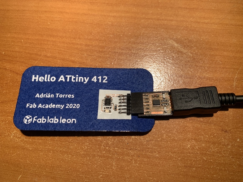
At Electronics Production Week make a board out of copper vinyl and an ATtiny412. I'm going to program it too.
- 1. I open Arduino. I configure the Arduino IDE for the ATtiny 412; I configure the clock to 20MHz, the TX and RX ports and in my case the communication port with the /dev/ttyUSB0 microcontroller.
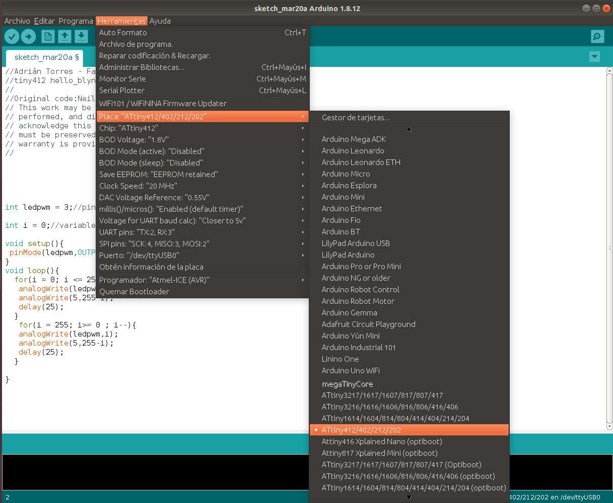
- 2. Only the code is compiled. In the Arduino IDE dialog box, we will see where the temporary files are located.
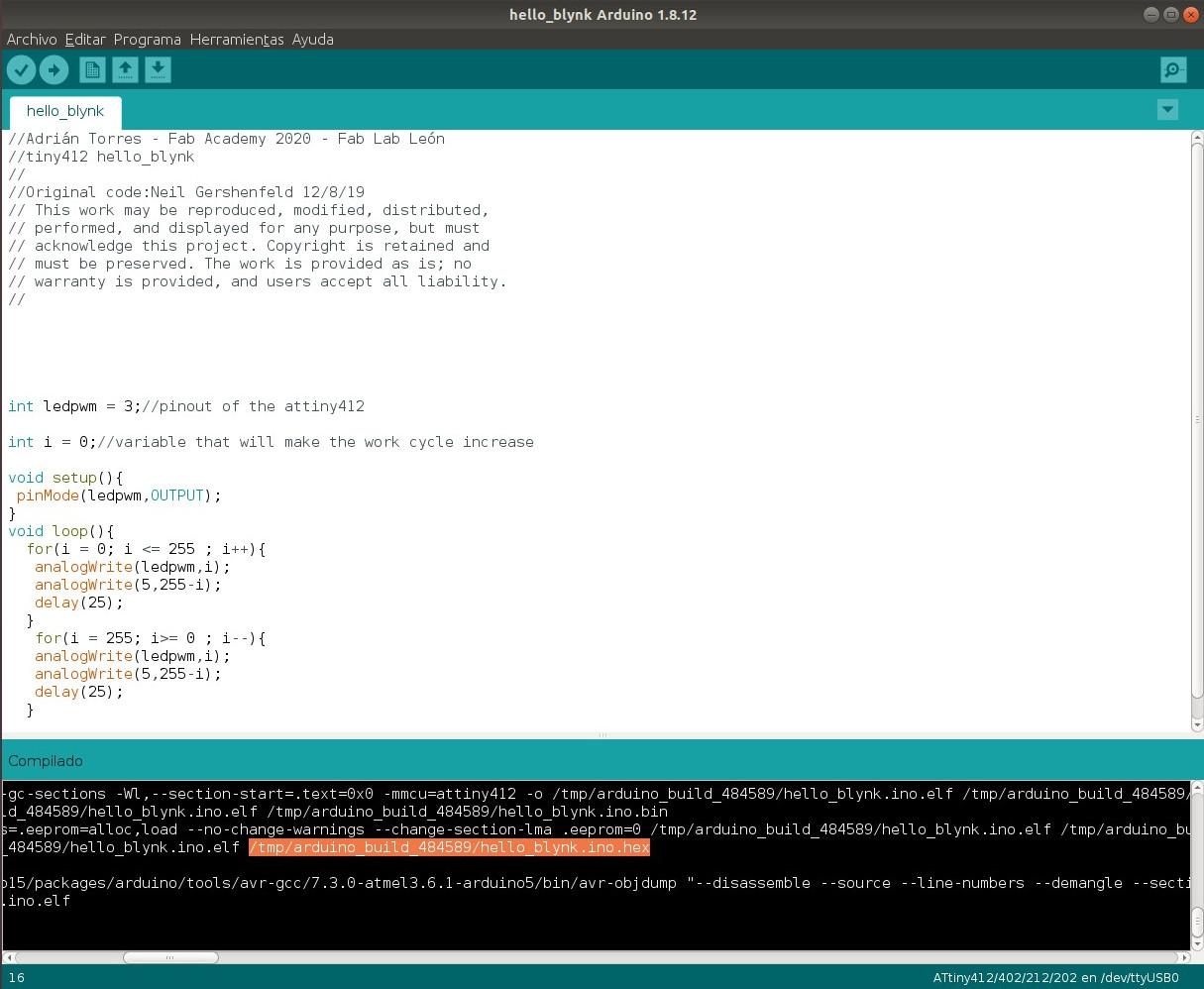
- 3. We look for the .hex file which is the one we need, it is in a temporary folder. Once located, we copy it and paste it in the pyupdi folder.
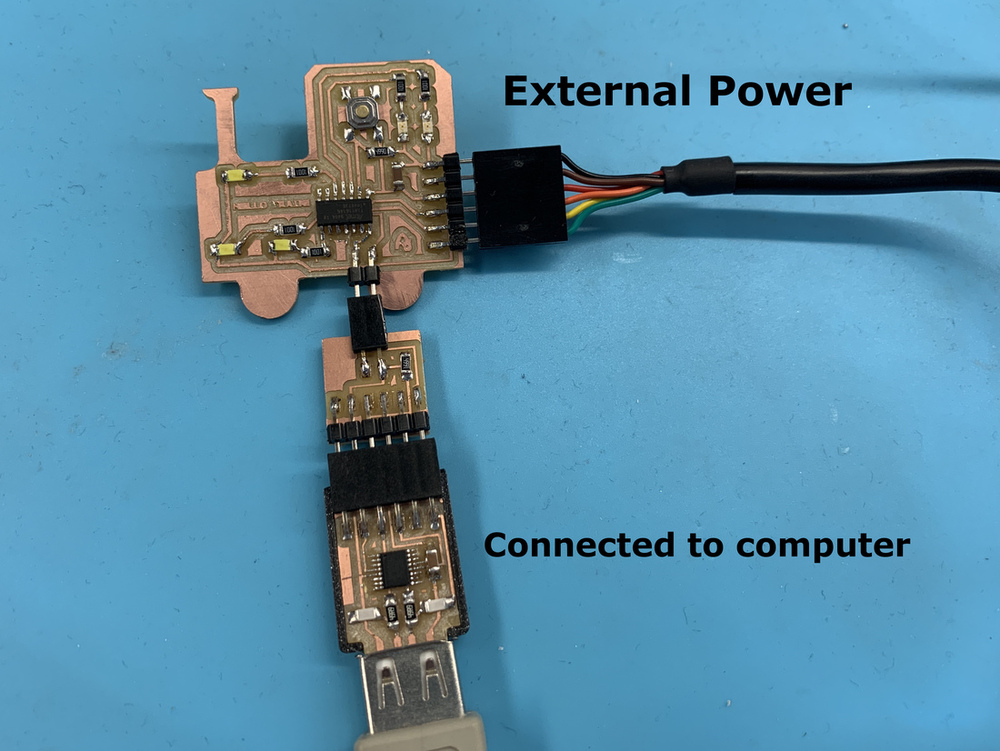
- 4. I connect it as follows. USB-Serial-FT230X + hello_ATtiny412.
- 5. Go into the "pyupdi" folder.
- 6. Program the board using python -> run sudo python3 pyupdi.py -d tiny412 -c /dev/ttyUSB0 -b 19200 -f Hello_blynk.ino.hex -v
Then change the name of Hello_blynk to Hello_intensity
Now it works, here is a small video. 😍
Here is the Arduino program to download.
//Adrián Torres - Fab Academy 2020 - Fab Lab León
//tiny412 hello_blynk
//
//Original code:Neil Gershenfeld 12/8/19
// This work may be reproduced, modified, distributed,
// performed, and displayed for any purpose, but must
// acknowledge this project. Copyright is retained and
// must be preserved. The work is provided as is; no
// warranty is provided, and users accept all liability.
//
int ledpwm = 3;//pinout of the attiny412

int i = 0;//variable that will make the work cycle increase

void setup(){
 pinMode(ledpwm,OUTPUT);
}
void loop(){
  for(i = 0; i <= 255 ; i++){
   analogWrite(ledpwm,i);
   analogWrite(5,255-i);
   delay(25);
  }
   for(i = 255; i>= 0 ; i--){
   analogWrite(ledpwm,i);
   analogWrite(5,255-i);
   delay(25);
  }
}
Atmel Studio 7
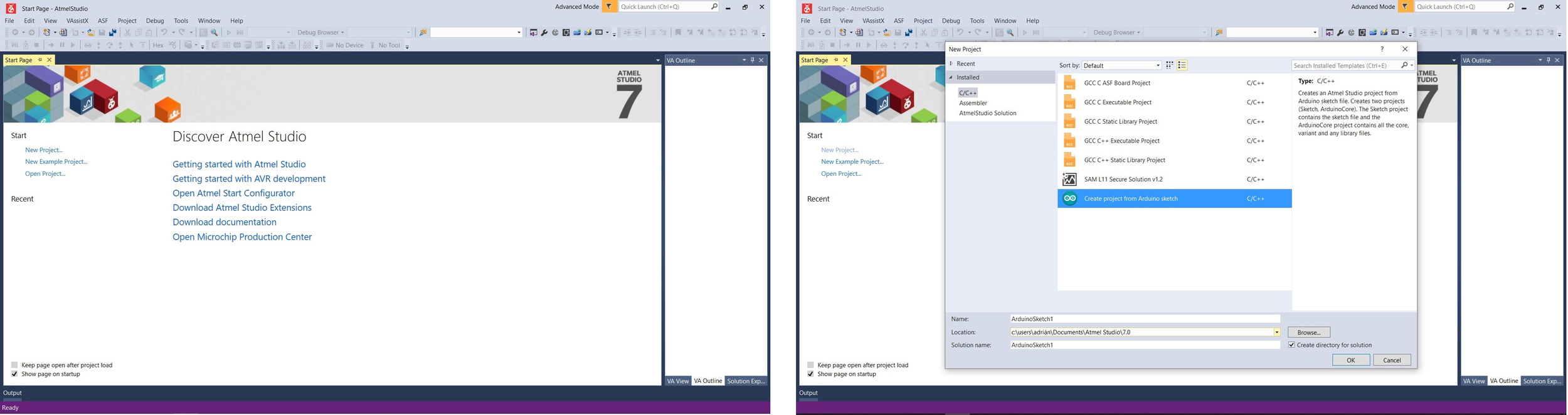
The first thing I do is download the latest version for Windows and 64-bit Atmel Studio 7 software. It has a very clean interface, and on the left you have to create the projects with different templates to program in C, C ++, or Arduino. For this I follow the following Microchip video tutorial.
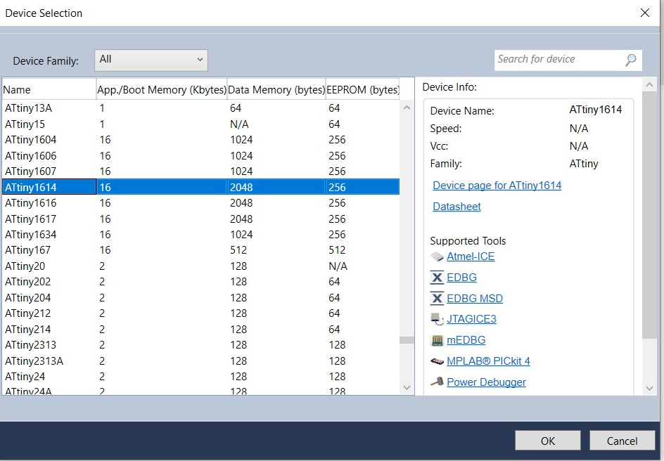
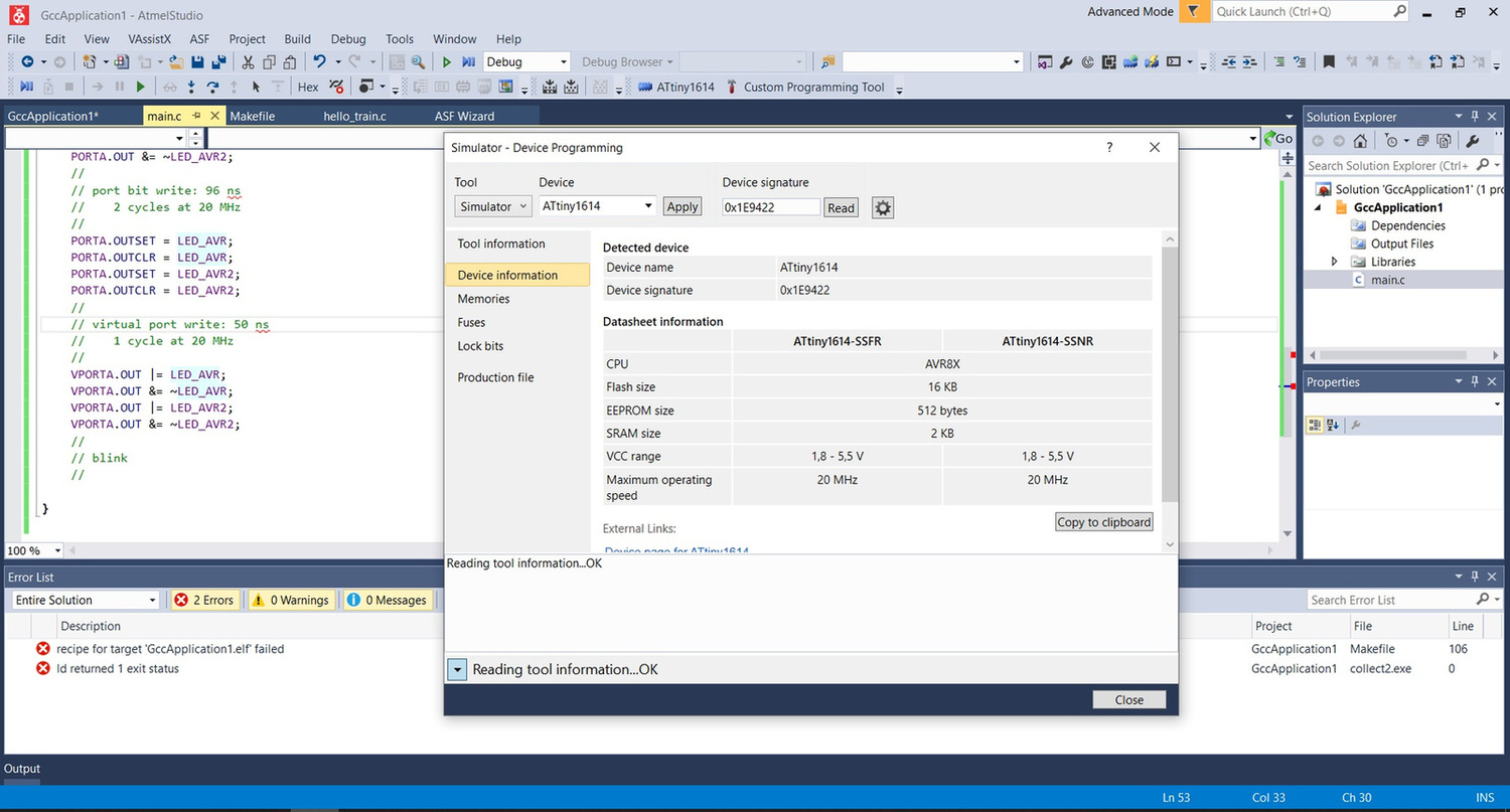
Since I have already used Arduino, I am going to use a C template. So the first thing I do is configure the device that I am going to use. In this case I want to use ATtiny1614; When you choose it, the Datasheet will appear, all the basic information and with which programmers you can use. Interesting. 🧐
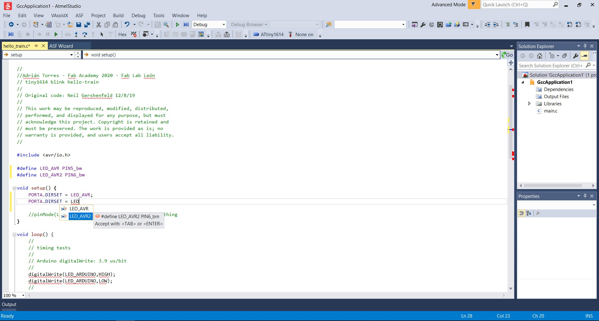
Once the device is configured; I go on to create the C program based on Neil's, but adding more LEDs. The program is very predictive and it tells you which port to use or the instruction auto-completes.
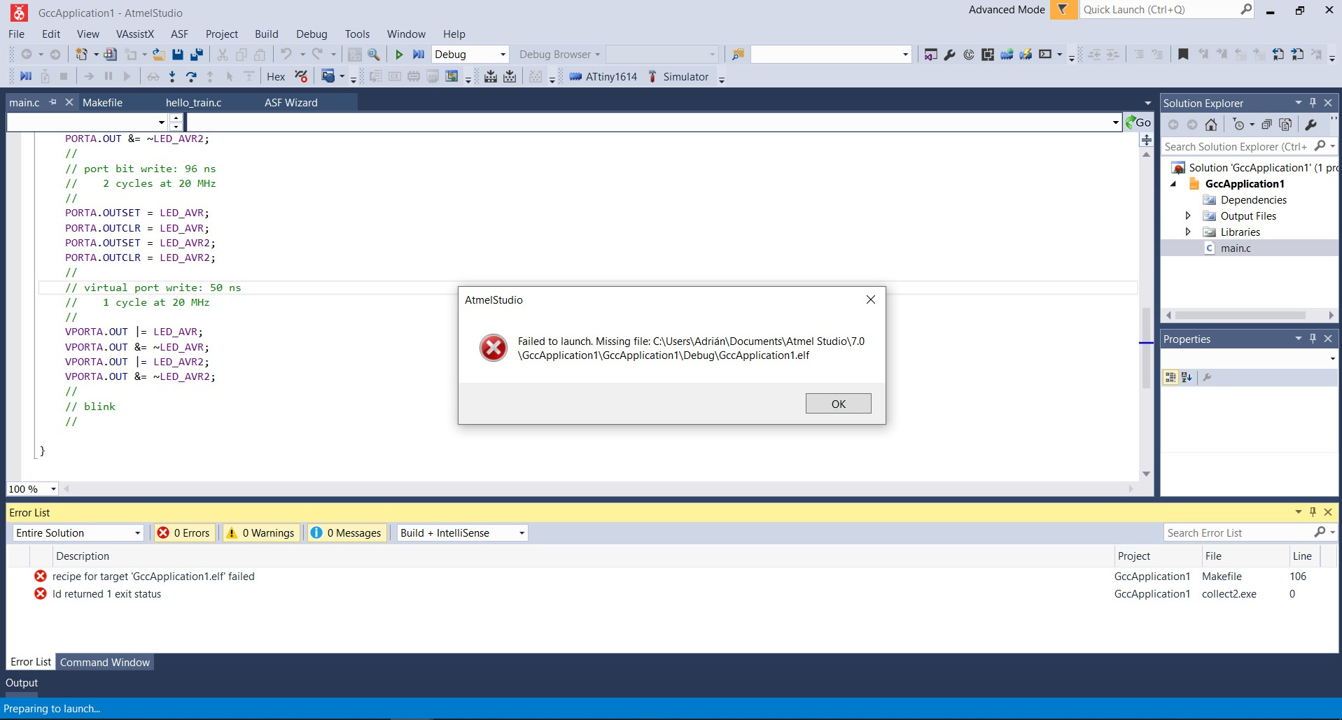
Once I have the program I debug, and it gives me a little error. It tells me that I am missing the file "GccApplication.1.elf". However, I am going to try to connect the board and try to pass the code to the microcontroller.
So I click on the Device Programming icon (a microcontroller with a lightning bolt) and the following screen appears where it only allows me to simulate, when I have connected my programmer and the board. I do not understand it, it is more my computer has recognized me the programmer and I have it in the COM4 port.
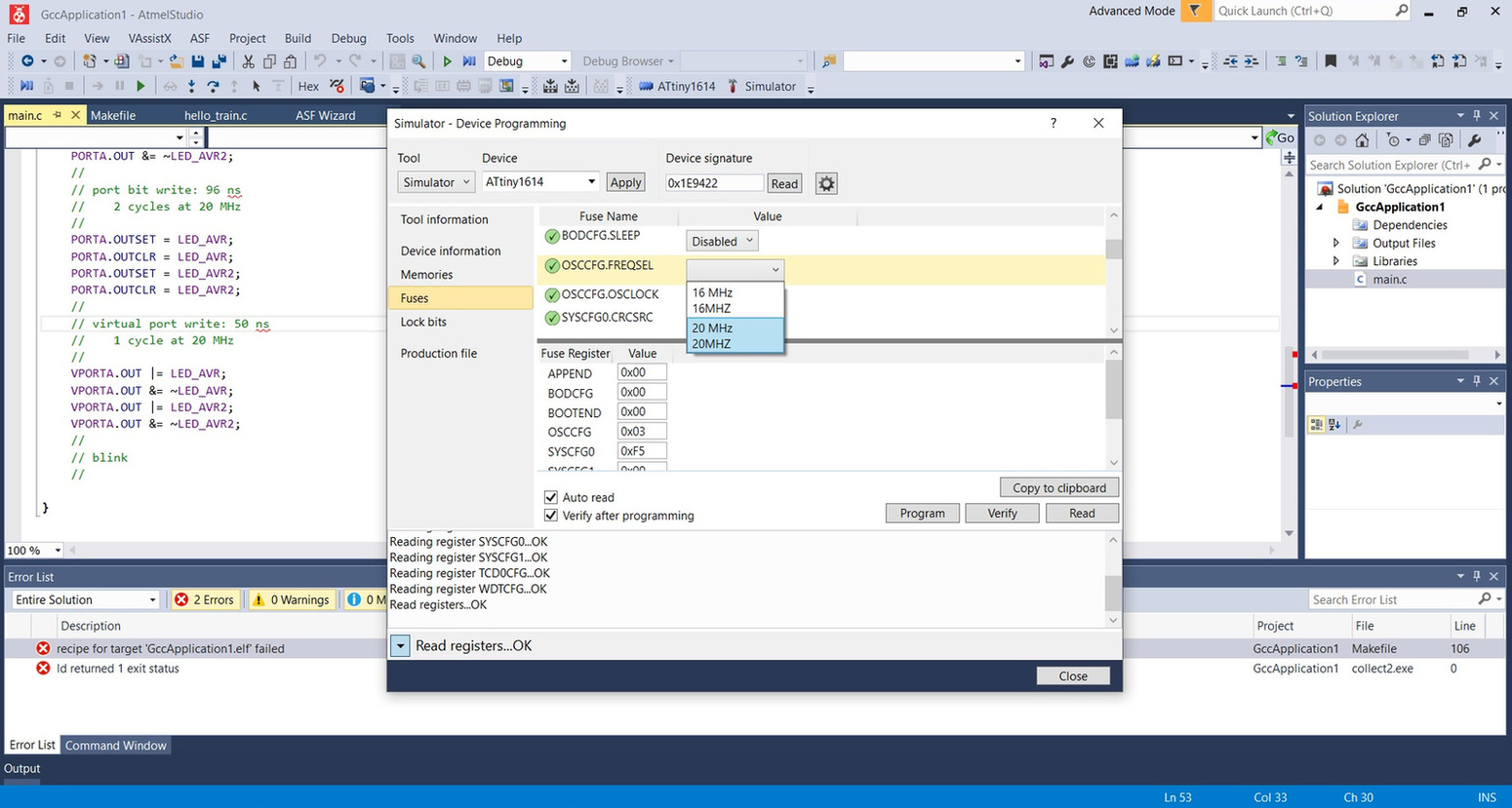
While I find out more about why my programmer does not recognize me, I go to configure the simulator toolchain. I set the ATtiny1614 to have the 20Mhz clock.
But I can't do anything, because it keeps giving me the same error, I am missing the file that ends in .elf. That file is very important because it groups together the toolchain as well as the .hex and the .makefile that are generated when debugging.
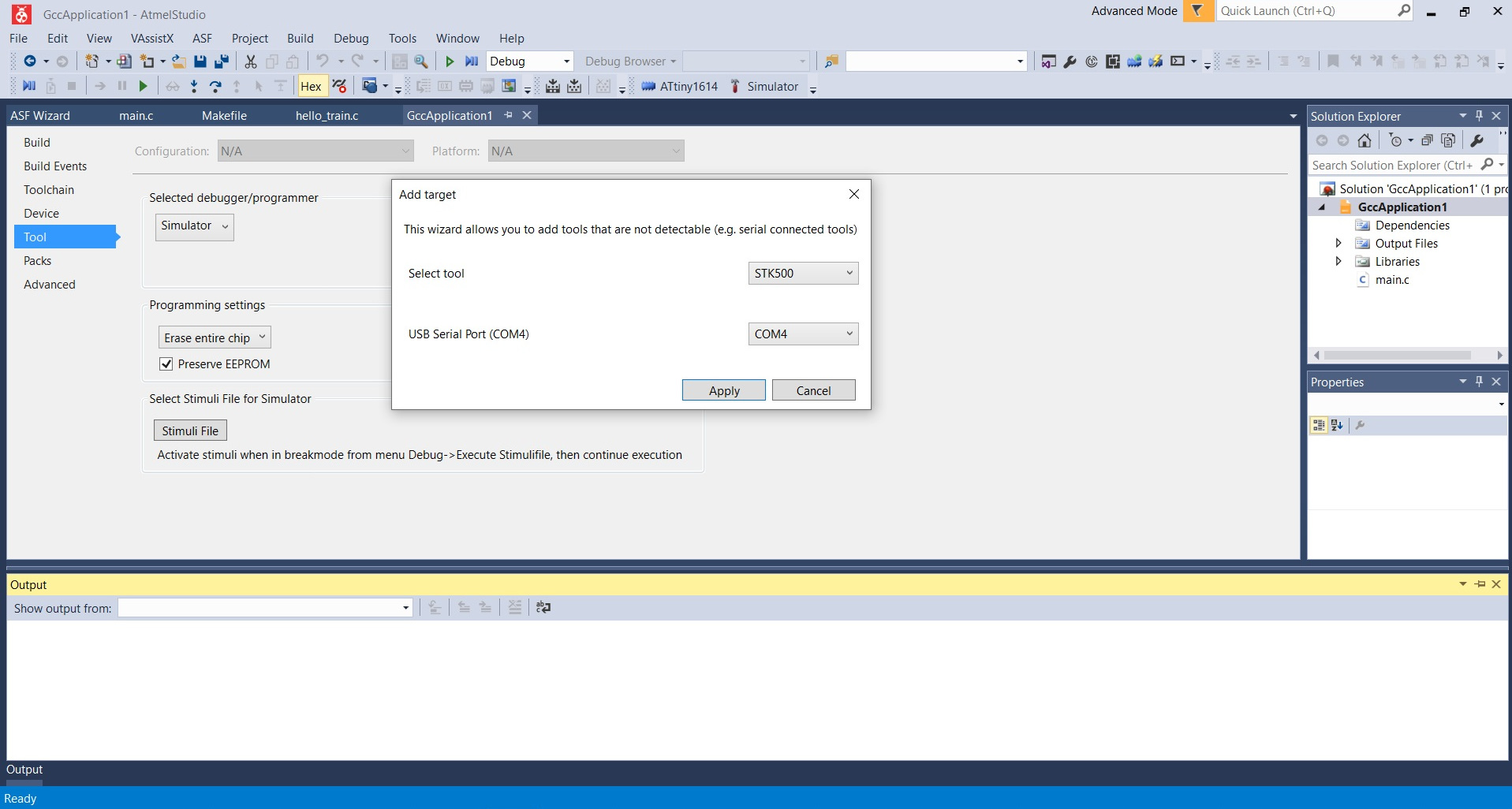
So since I can't simulate, I keep investigating the software and suddenly find that a target can be added to the tools menu. And it recognizes a STK500 that I have connected to my computer in COM4. Yuhuuu. 😃
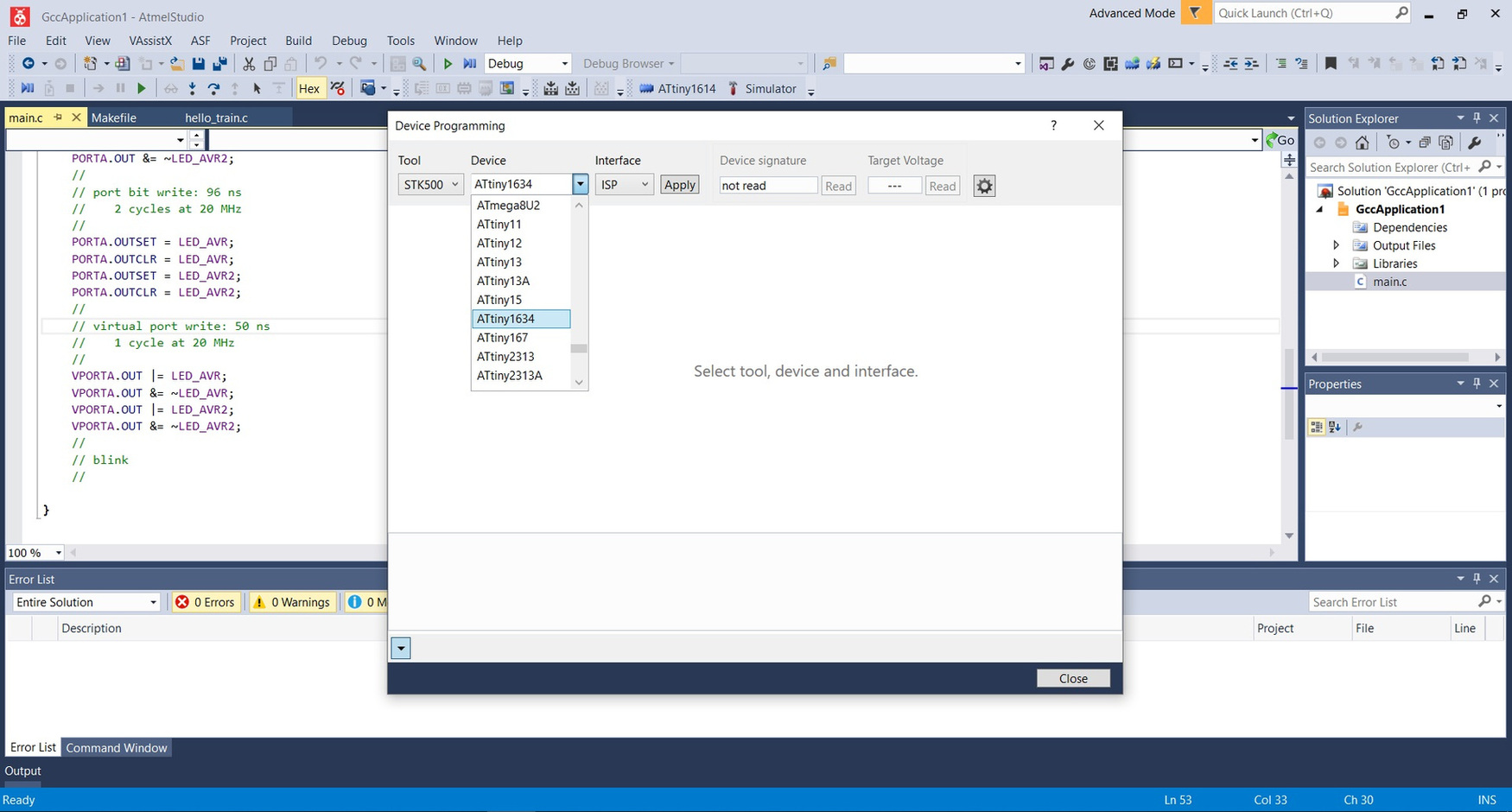
But ... when configuring the toolchain, there is no ATtiny1614 and neither is ATtiny412, so I can't do anything else. I have updated it and neither does ATtiny´s appear.
So, in conclusion it has a good working environment, predictive, it has the datasheet, simulator ... but it doesn't work for me, it could be the .elf file.
Group Assignment. Different microcontroller families.
PIC
During my professional training we study the PICs and to program in assembler. It used PIC 16F84A. And I had the following list of instructions to program. Loading instructions, arithmetic, logic, jumps, subroutines and specials. Here I leave my sheet of notes, sorry for the state, he is 11 years old.
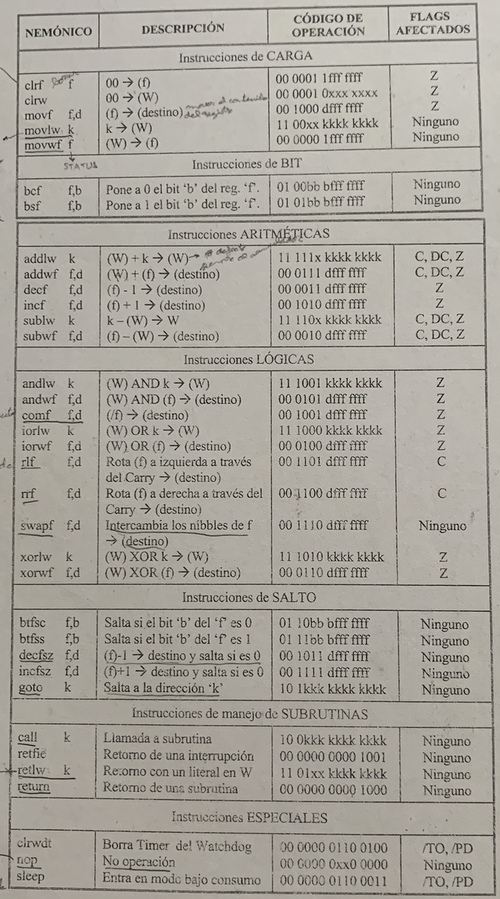
This is an example of a program to generate a 1kHz signal on Port B6
                            _CONFIG _CP_0F& _WDT_OFF&_PWRTE_ON&_XT_OSC; recorder settings
                            LIST   P=16F84A
                            INCLUDE

                            ORG0
                START       bsf STATUS,RP0
                            clrf TRSIB
                            movlw b'00011111'
                            movwf TRISA
                            clrf OPTION_REG
                            bcf STATUS, RP0

                PRINCIPAL   bcf PORTB,6
                THERE       movlw d'6'
                                    movwf TMR0
                HERE        btfss INTCON,2
                                    goto HERE
                                    comf PORTB, 6
                                    bcf INTCON, 2
                                    goto THERE


                                    END
At the time of programming we used Microchip's MPLAB to compile and obtain the hexadecimal file. Once we had the hexadecimal file with the IC-Prog application through Serial connection and the photo programmer transferred the hexadecimal file. Then we had a simulation board where we could see the different states of the Ports.
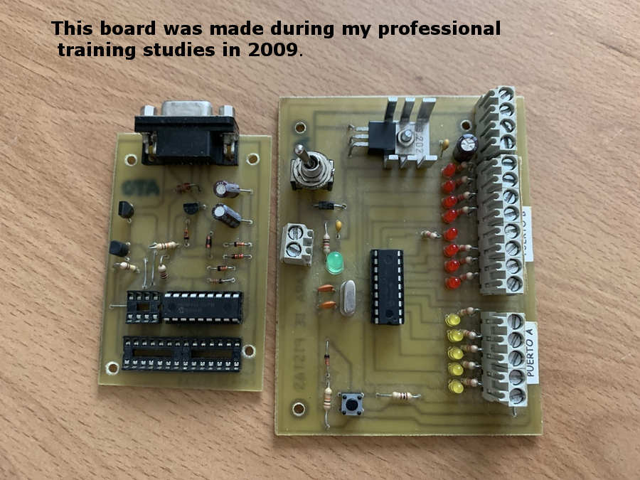
As my computer does not have a Serial connection, but I had some PICs programmed, I have put the simulation board back into operation. The video program is of a prototype of a tram that moved in a straight line section forwards and backwards. I used PWM, that's why the LED lights up from less to more and vice versa. 🚃
Micro:bit
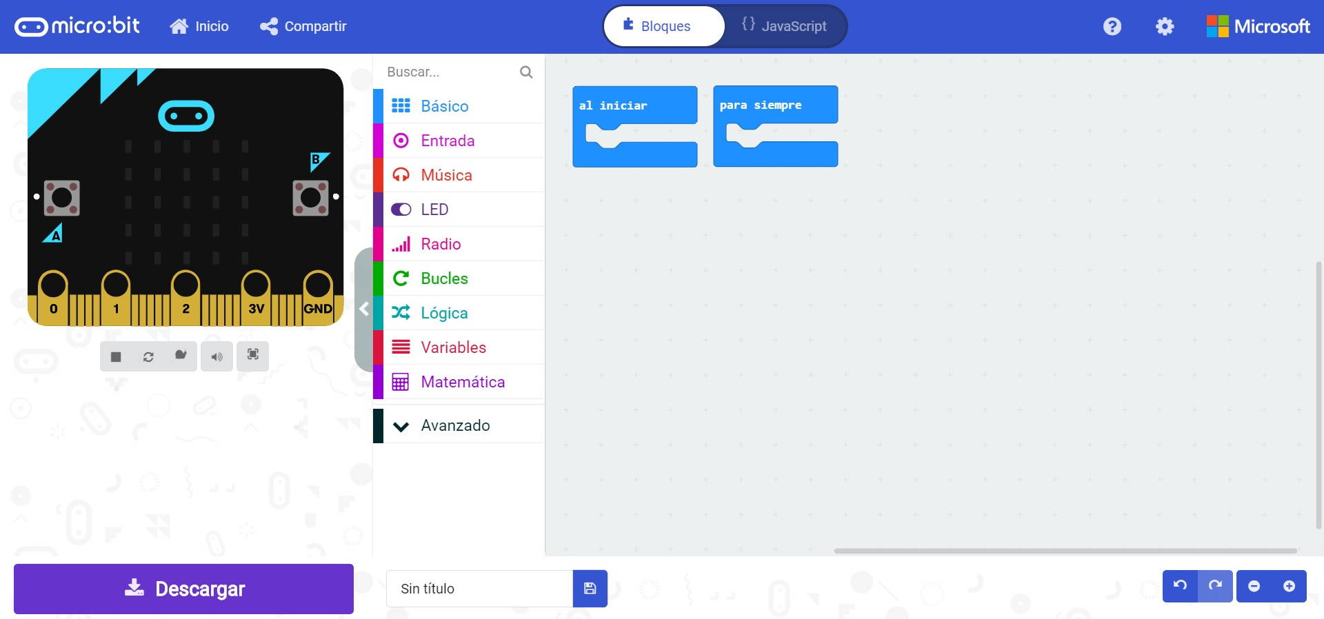
Well, in the Fab Lab León we have this small board with many features. Young Makers use it in their projects. In my case, I follow this BricoGeek video tutorial to get to know it a little more.
Before connecting the board to the computer, I go into the browser to search for Micro:bit Editor. The board appears to simulate on the left, a central column with the different basic instructions and on the right the area of the program where you can do it in blocks or in JavaScript.
Then it is as simple as seeing if we want to do routines, or a single cycle. I make a basic program that when I turn on the Micro:bit says Hello! If I press button A it makes me a ✔ and button B makes me ❌. If I press both buttons A + B it tells me the temperature of the room. Once the program is finished, it is as easy as saving and downloading it. The file is a .hex file that we will copy into the folder that appears on the computer when we connect the Micro:bit.
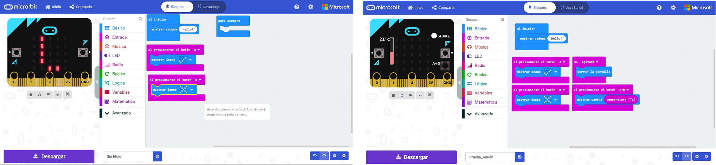
Once the .hex file has been copied to the Micro: bit, it does the following in the video.
Here is the Micro:bit program to download.
FPGA
An FPGA is a field programmable logic gate array. In Spain there is a movement that encourages the use of free FPGA's created by Obijuan. Thanks to Obijuan, I create a Jedi Academy, using GitHub and video tutorials to learn this programmable electronics.
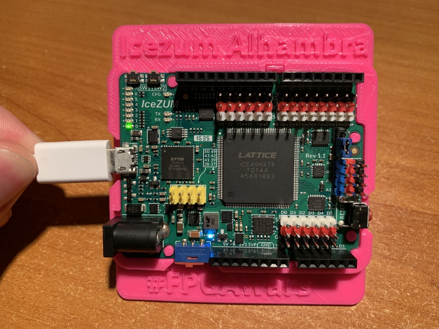
In 2016, Eladio Delgado created the Icezum Alhambra. If you want to buy it, here is the link.
The first Icezum Alhambra were crowdfunding, in this case Nuria sponsored one. 😍
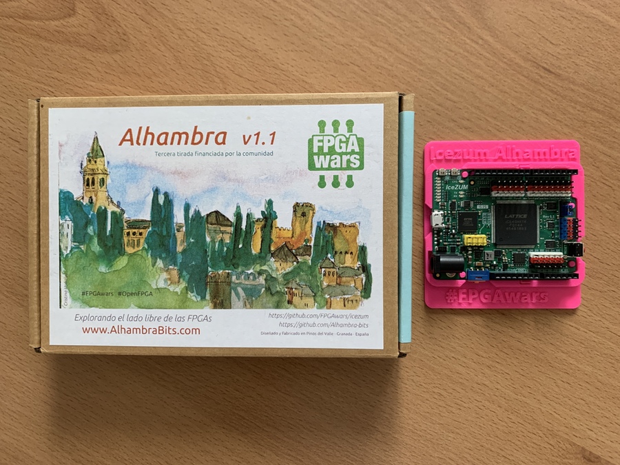
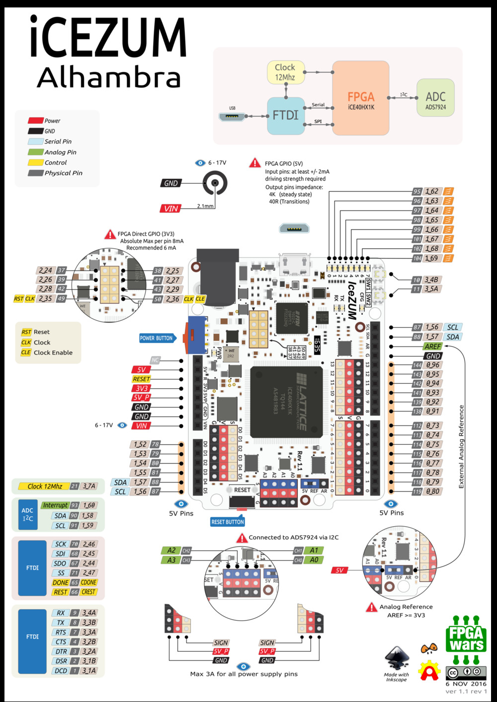
This is the pinout of the board.
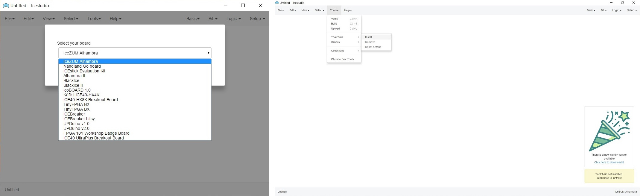
To program it we need the Icestudio, which we will download from the following link. Once installed, we have to choose the board, in this case the Icezum Alhambra. Then we must install the Toolchain, in the Tools menu.
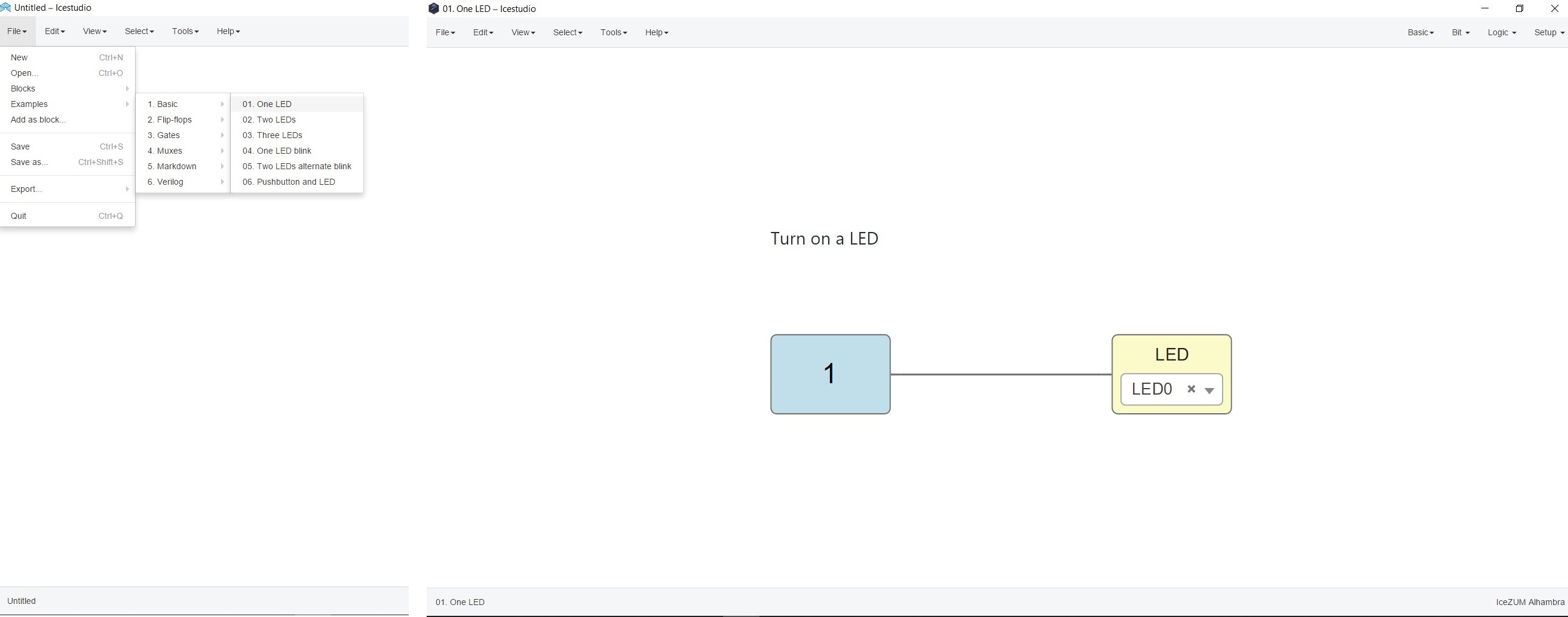
Once the toolchain is installed, the first thing the tutorials recommend is to open a simple program. They are small blocks of inputs / outputs, logic gates, signal generators ... In this case I am going to light LED 0.
Now it's time to connect the board to the computer using a mini-USB cable. As soon as we connect, this message appears, where we must configure the FTDI. We will install the drivers with the Zadig tool (Interface 0) (importantly we will always connect the board to the same USB).

Inside the Tools menu is the Upload button. We press it and we get this on the board. LED0 illuminated. 😊
Once I have discovered the tool and the handling, I decide to make a simple program, I want the even LEDs to light up and the odd ones off and vice versa in a sequence. I use a random blink program as a reference and start adding more LEDs. Then I combine NOT, NAND and XOR gates to create the following program. From here I want to thank Julián Caro Linares for solving any questions telematically.
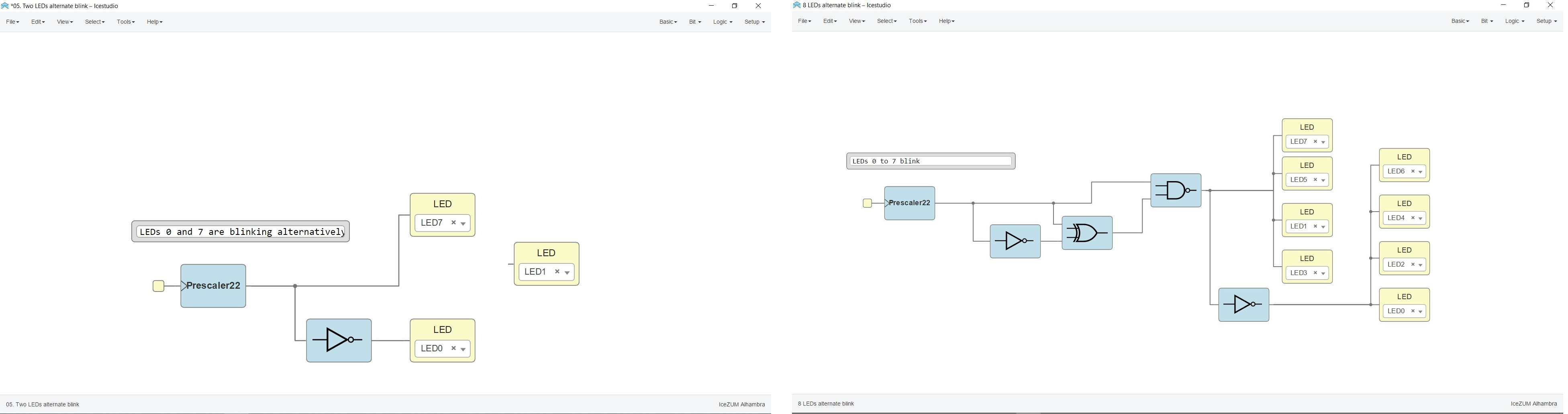
Once loaded this is the video result. 🤗
FPGA is very interesting, a very powerful tool that can be programmed very easily with logic gates.
Here is the Alternative blink program to download.
Review of the class
During the review of this class I volunteered with the FPGA in the minute 1:13:00. 😊
20200325 Embedded Programming review from Academany on Vimeo.
Files
Find below the files that I made for this assignment.