Networking and communications
Week 15
Like every week I started the week planning the assignment.

I'm doing this assignment in the week 16th as we decided to use the week 15th to meet all together in Leon and design, fabricate, assemble and program the machine.
Serial BUS
Ultrasonic sensor + Stepper motor
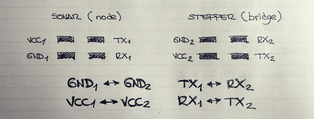
Since I had this assignment in mind when I designed my PCBs for input and output weeks, I only had to program the microcontrollers properly because I already had the communication connectors available on the PCBs (2x2 pin header: GND, VCC, TX, RX).
To understand how the serial communication works, I decided to try with a sketch connecting the ultrasonic sensor and the stepper motor, in such a way that the motor is continuously moving while the sensor gets readings greater than 7cm. When the distance is less than or equal to 7 cm, the motor should stop.
Having as a reference the Szilárd A. Kados's assignment, I created in Arduino IDE two sketches (one for the motor, another one for the sensor) using the Software Serial Library. I used Serial_sw.write() to save the readings from the sensor board; serial_sw.available() to recieve the data from the sensor board in the motor board; and serial_sw.read() to read the data in the motor board and used it to control its movement. Then I separately uploaded each sketch to each microcontroller.
Finally, I connected the two boards following the diagram below. The most important thing here to keep in mind is that the pin that is going to send the information need to be connected to the one that will receive it, so TX and RX must be crossed.
And with the two boards previously connected, I powered up the circuit with a battery.
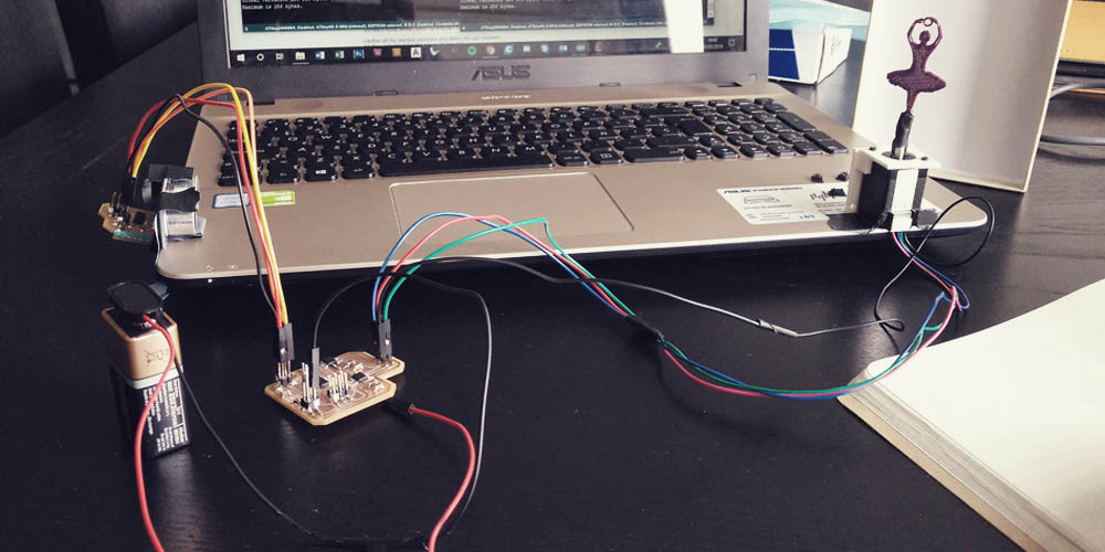
And it worked pretty well!! But I realized that when the ultrasonic sensor wasn't reading anything because the limit surface was too far away, the motor continued moving but it reduced the speed, and I don't know why...
At first, it was difficult to understand how serial communication works in the code. But then I realized that the underlying logic, in this case, is very simple: the node board is a kind of emitter and the bridge board is a receiver that uses that information emitted to do something, such as moving a stepper...
Extra: Fabkit
After this week I realized that would be very useful to have my own Arduino, in order to try different inputs and outputs devices without having to mill a PCB for each one. You can find more information in Final project. First prototype.
Serial BUS
Phototransistor + Relay (LED Bulb)
I am adding this part of the assignment in the week 19 while developing the second prototype of the final project.
Keeping as a reference the code and system that I followed to achieve the networking between the ultrasonic sensor and the steeper, I started making the code to connect a phototransistor and a LED bulb, through a relay. I did both codes and I uploaded independently to each microcontroller. Then I connected the bridge with the node following the "serial bus rule" (tx1->rx2, rx1->tx2) and I powered up the system through an FTDI cord to the computer.
The idea was that when the phototransistor is reading a lot of light the relay is off, so the bulb is off too, and when the phototransistor is reading a very little of light, the relay is on, so the bulb is on too. However, with the first code that I did, when the phototransistor was reading a lot of light, the relay wasn't able to keep off... It started blinking very fast... You can see below what happened...
I asked my instructors and they suggested me to filter the data of the phototransistor before sending it to the relay PCB, as probably the problem was that I was sending so much information that the PCB bridge is not able to manage it, so the relay gets crazy. So I did a second code, in which using the code included in Arduino IDE > file > examples > analog > smoothing, I could filter the data of the phototransistor. So I uploaded the new code, and now it worked much better!!
Finally, with the code/system working, I also wanted to place the bulb on the lamp and see how it looked like...
Being honest, I don't know why the relay blinks three times (always three times...) before staying in position, I didn't add in the code anything to do that. I was a bit worried about that so I keep the lamp powered up during around one hour, turning on and turning off the room light each 5-10-15 minutes to see what it does, and the relay always keeps stable after those three blinks... I think is because of the average data that the phototransistor's PCB is sending, that when the light changes the data is inestable during a few seconds... But anyway, I like it, it's as if the lamp was warning you: ei! I'm going to turn off!!, ei! I'm going to turn on in a few seconds....
Files
Find below the files that I made for this assignment. Please do not hesitate to download it!! I hope you enjoy it!!
Ultrasonic sensor (Node) - .ino
Steeper motor (Bridge) - .ino
Phototransistor (Node) - .ino
Relay_LED Bulb (Bridge) - .ino