First prototype
Version 3.0
I continued working on the 3D file (I used Rhinoceros 3D) but this time my goal was to fabricate the first prototype. The vertical structure will be fabricated in PLA by 3D Printing, and the horizontal and basement structure in MDF of 3mm. by laser cutting.
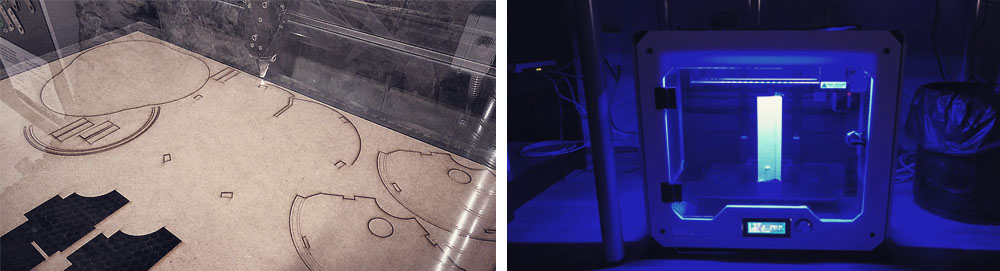
In comparison with the previous design, I reduced the height of the basement, since I decided to use an infrared proximity sensor (Sharp GP2Y0A02YK0F,) insead of an ultrasonic sensor, which is smaller so I need less space. The hight of the machine is limited by the maximum height that my 3D Printer can support (200mm.).
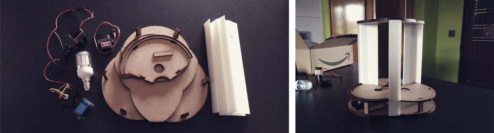
So, in the base, the idea is to place the servo motor, relay module and infrared proximity sensor (connected to the same bridge PCB) and two batteries (one of 12V to power up the LED bulb and another one of 9V to power up the bridge PCB). At the half height, we have the light bulb and, coupled to the top lid, I placed the phototransistor attached to its node PCB, which is connected to the Bridge PCB by serial BUS.
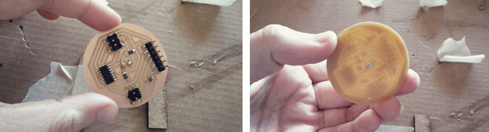
I also designed, fabricated, soldered and tested the final (hopefully) version of the phototransistor's PCB. The phototransistor is paced on one side of the board and the rest of the components are on the other side. The top lid of the lamp has a hole from when the phototransistor can read the ambient light level while I can connect the cables from the other side, having an integrated design.
To tested I used the same program that I wrote in the input devices week.
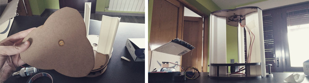
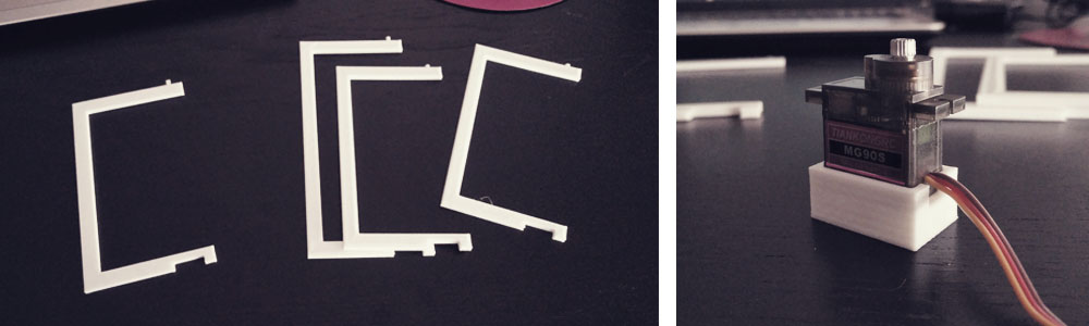
Then, I design the cross that will be connected to the motor and will fold and extend the external layer of paper. I decided to fabricate it in plastic with the 3D printer, as the plastic is a very light material and, although the servo motor that I am planning to use is an MG90s with metal gears, I prefer to not force the system. I had to print several times the cross: in the first version I took wrong the hight, so the cross was bigger than it should be, and in second and third version, although I was taking the correct measurements from the digital file, in the physical versions of the lamp the distances are a bit different, so I had to adjust the design by testing. The fourth version was the good one.
I also made with the 3d printer a base for the motor, so I don't need to screw it.
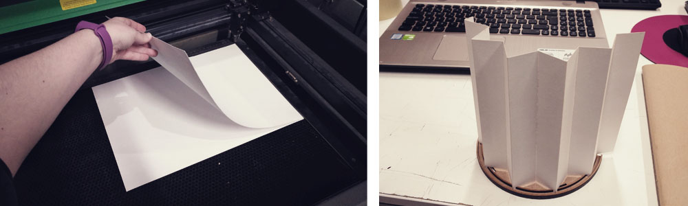
After that, I made the design for the paper. I measured the length of the circumference and I created the file for laser cutting. I engraved the lines for folding, and I put under the paper another paper to avoid to burn the paper in the bottom side (thanks Nuria for the trick!).
But at the moment that I saw the paper on the rail and I did some test by hand, I realized that I will need a second rail in the upper part to hold the paper properly. So I have to redesign that part.
But before to go to the next version of the lamp, I decided to run a test with the motor and the cross installed in the structure. First of all, I had to find out the position 0 of the motor and then, using the PCB that I did for programming servos in the in output devices week, I tested the design. The first motor that I used didn't work at all, for some reason it wasn't able to turn more than 50-60º and I need 155ª so I try with another one (same brand, same model...), and it worked!!.
During this step of the process, I also tested the infrared proximity sensor. You can find more information about this in input devices week.
Fabkit
In order to try the different connections between different output and input devices, I decided to do my own "Arduino" before milling the final PCB.
I used as a reference this tutorial. I decided to do the versión 0.4. So I downloaded the Eagle files and I made some modifications.
This is the list of components that I used:
> 1 x Atmega328P (IC MCU 8BIT 32KB FLASH 32TQFP)
> 1 x 10kΩ resistor (RES SMD 10K OHM 1% 1/4W 1206)
> 1 x 499Ω resistor (RES SMD 499 OHM 1% 1/4W 1206)
> 2 x 0,1uF capacitor (CAP CER 0.1UF 250V X7R 1206)
> 1 x 1uF capacitor (CAP CER 1UF 50V X5R 1206)
> 1 x 10uF capacitor (CAP CER 10UF 35V X7R 1206)
> 1 x Switch (SWITCH TACTILE SPST-NO 0.05A 24V)
> 1 x Xtal 8MHz (CER RES 8.0000MHZ 22PF SMD)
> 1 x LED (LED BLUE CLEAR 1206 SMD)
> 31 x Pin header 2,54mm.
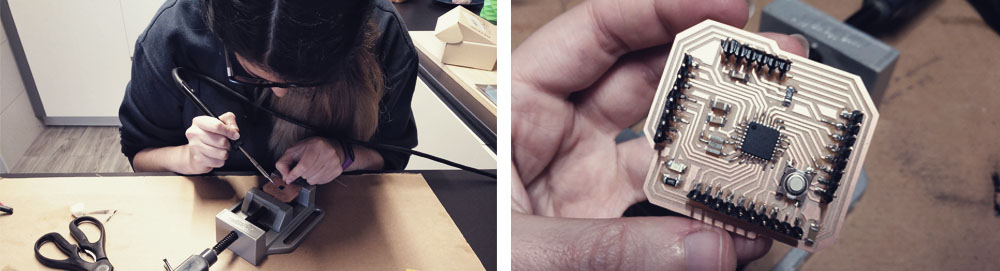
I was a bit scared about soldering the Atmega but you only need patience and good pulse (and a soldering iron tip of 0,5mm.).
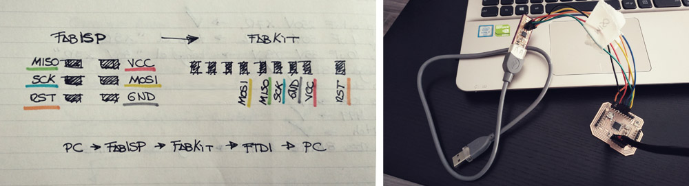
To program de Fabkit I followed this tutorial. You have to be careful connecting the dupont cables, so I did the below diagram to avoid mistakes.
I had some "problems" while programming:
.- The LED of the FabKit didn't light up when I connected everything to the computer. I realized that I placed the component in the wrong direction, so I had to unsoldering and solder it again. Then, the LED started lighting.
.- I had the FabISP connected to the computer, and to the FabKit through the six dupont cables, and the FabKit connected to the FTDI. Then, when I connected the FTDI to the computer, the computer started making that typical noise that Windows does when you connect a USB, but repeatedly and non-stop, like if it was reading and not reading, connecting and disconnecting, the FabKit. I realized that this was due to the reset (RST) connection. So, to burn the bootloader I had to, first, connect everything excepting for the reset cable, and then, connect that reset cable.
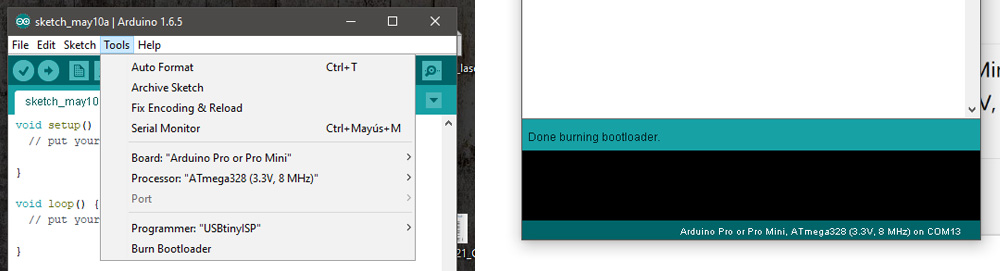
To burn the bootloader, through Arduino IDE, I chose "Arduino Pro or Pro Mini" as the board, "Atmega328 (3,3V, 8Mhz) as the processor, and "USBtinyISP" as the programmer. Then I burn de bootloader and it worked! Now you can program the board directly through the FTDI cable.
Note: when the FTDI and the FabKit are powered up (connected to the PC), and you haven't uploaded any programme in the microcontroller, the LED blinks all the time. It seems that is normal. Don't get crazy (I did).
Files
Find below the files for the fabkit. Please do not hesitate to download it!! I hope you enjoy it!!
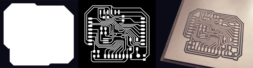
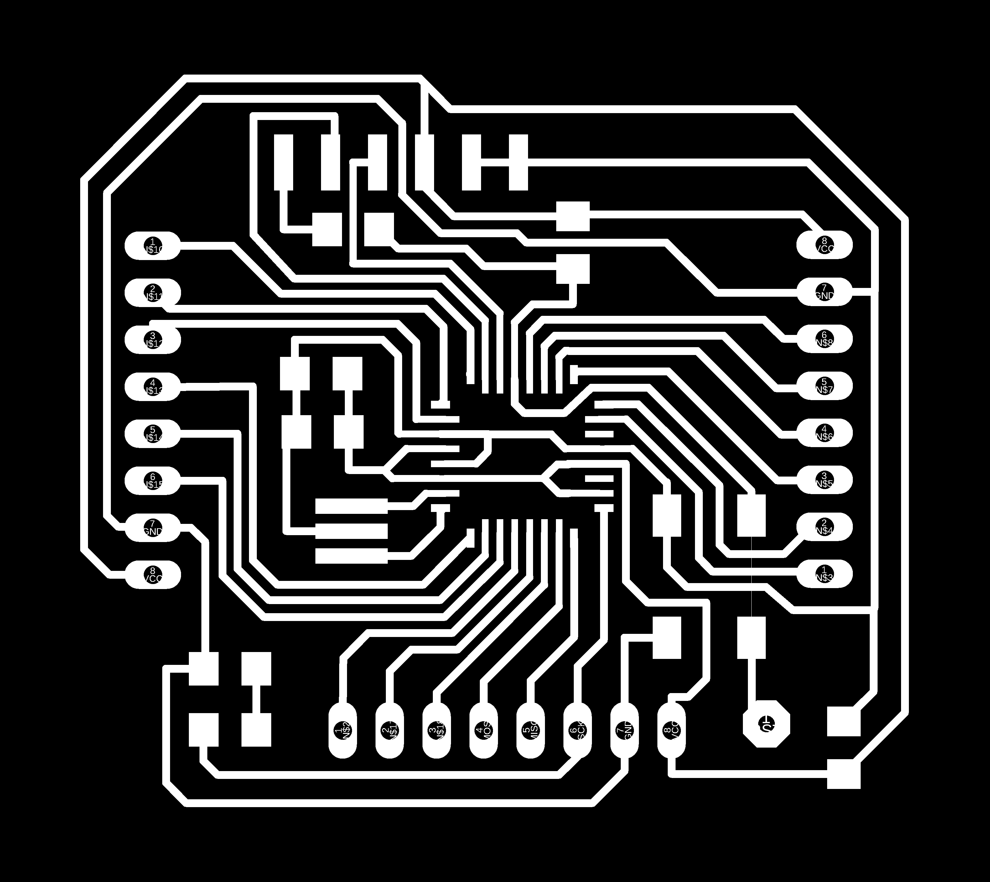
Fabkitelena_traces - .png
Fabkitelena_outline - .png
Fabkitelena - Eagle schematic + board