13 - Networking and communications

This week, we will learn how to program communication between devices.
This week, we will learn how to program communication between devices. A network always has to contain more than two devices talking to each other.
Assigments
- individual assignment:
- design, build, and connect wired or wireless node(s)
- with network or bus addresses - group assignment:
- send a message between two projects
Individual Assigment
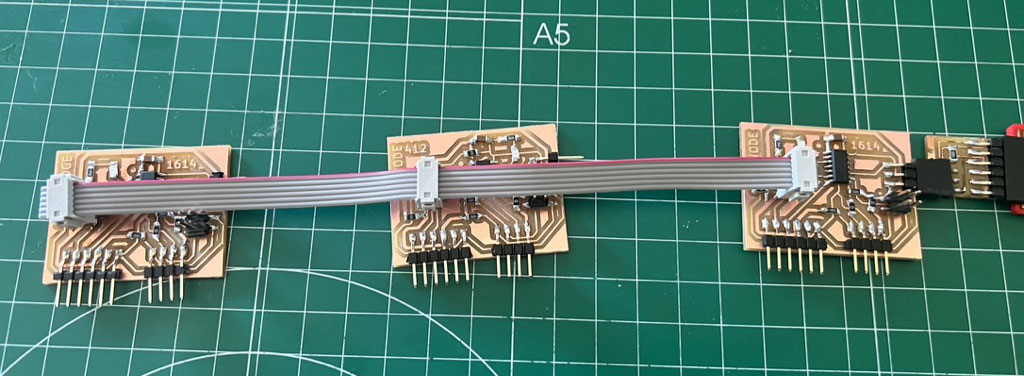
The initial idea is to create 3 pcb, one of a bridge that sends data to 2 boards, and these interact depending on the received message.
I will create a first bridge plate and 2 nodes.
Made boards
For the bridge I will use an Attiny1614 and I will enable both RxTx and I2C ports to be able to test with the 2 configurations.
Additionally, a simple node will be with an Attiny412, the minimum to make it work since we have RxTX and I2C in only 8 microcontroller pins.
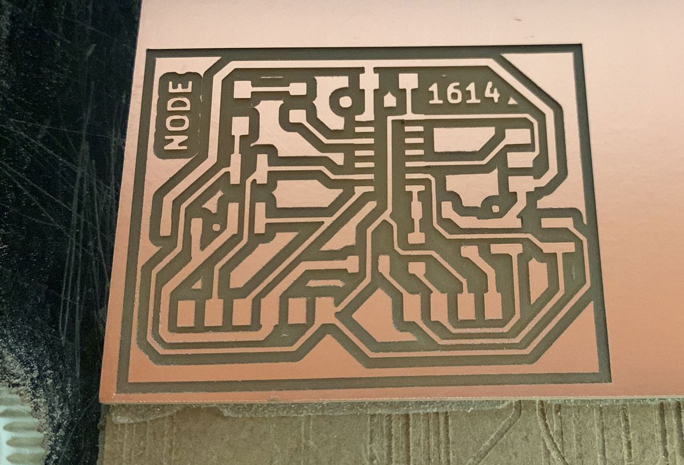
The other node will be an Attiny1614, again more powerful to add an OLED and display results directly on the screen.
All pcb have an LED to emit visual signals.
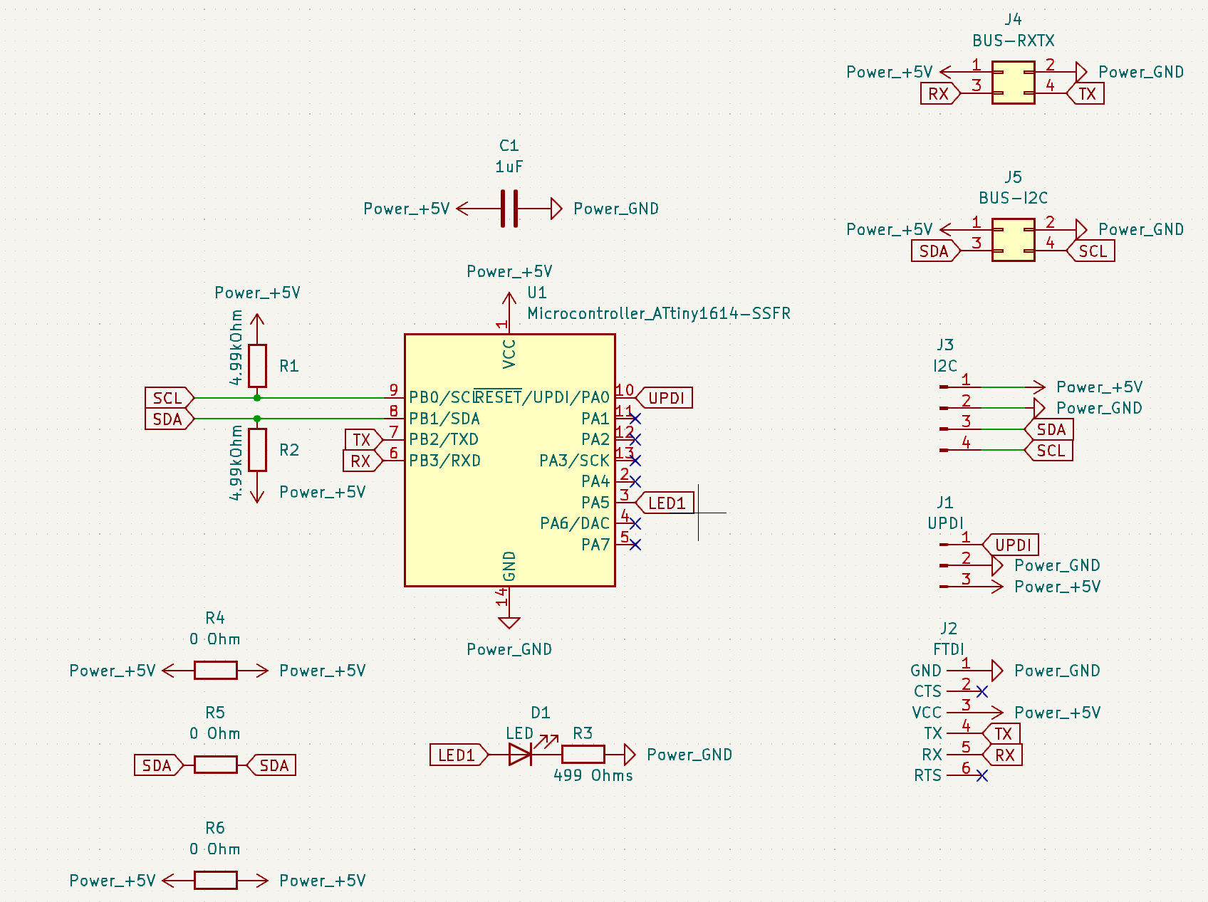
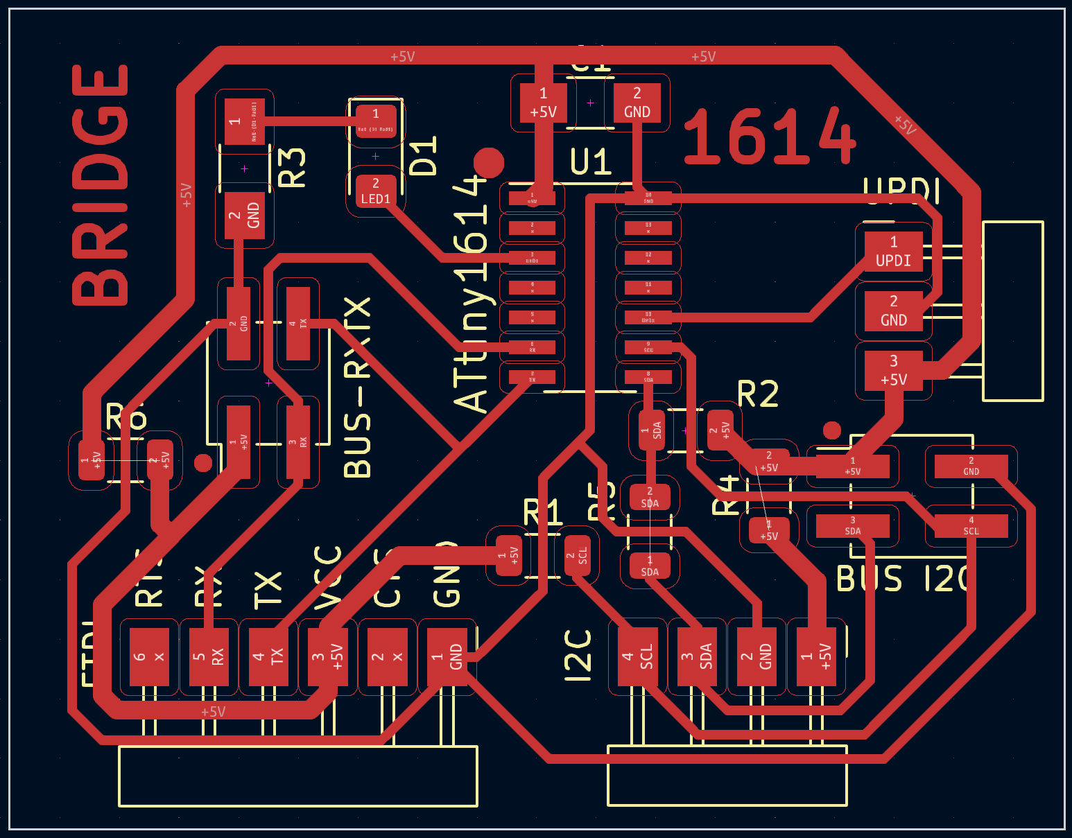
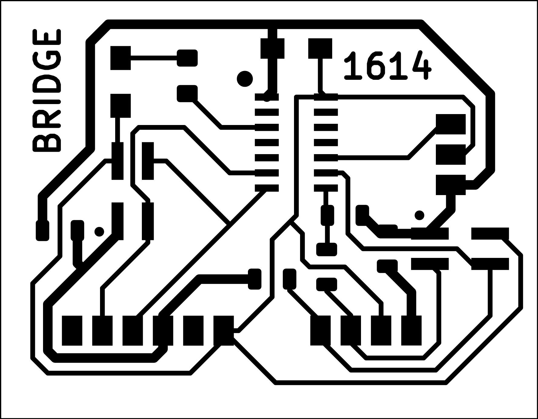
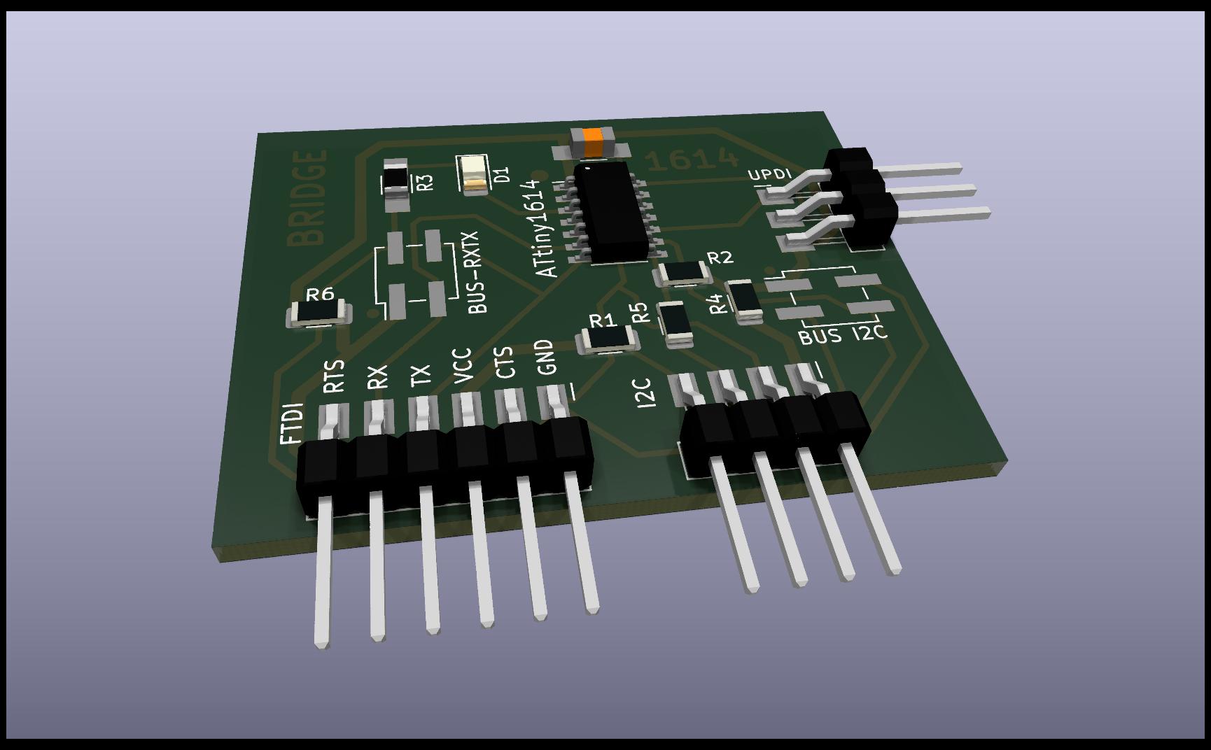
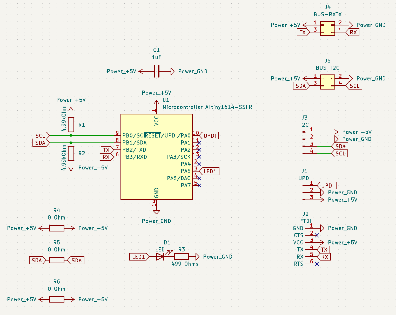
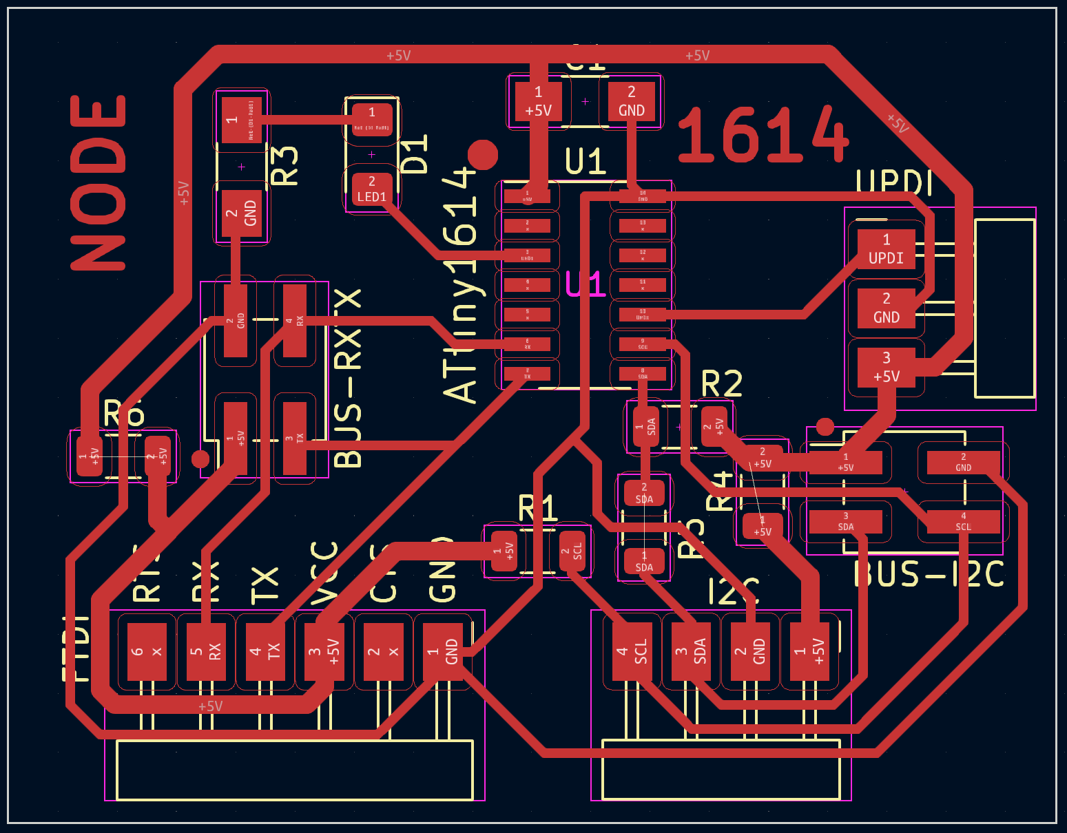
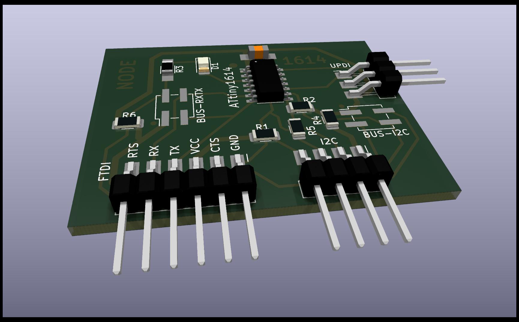
Bridge Attiny1614
To do the layout, I turn to KiCad, starting with the pcb schematic. In addition to FTDI, UPDI, I2C enabled 2 buses with vertical pins to easily connect the boards to each other.
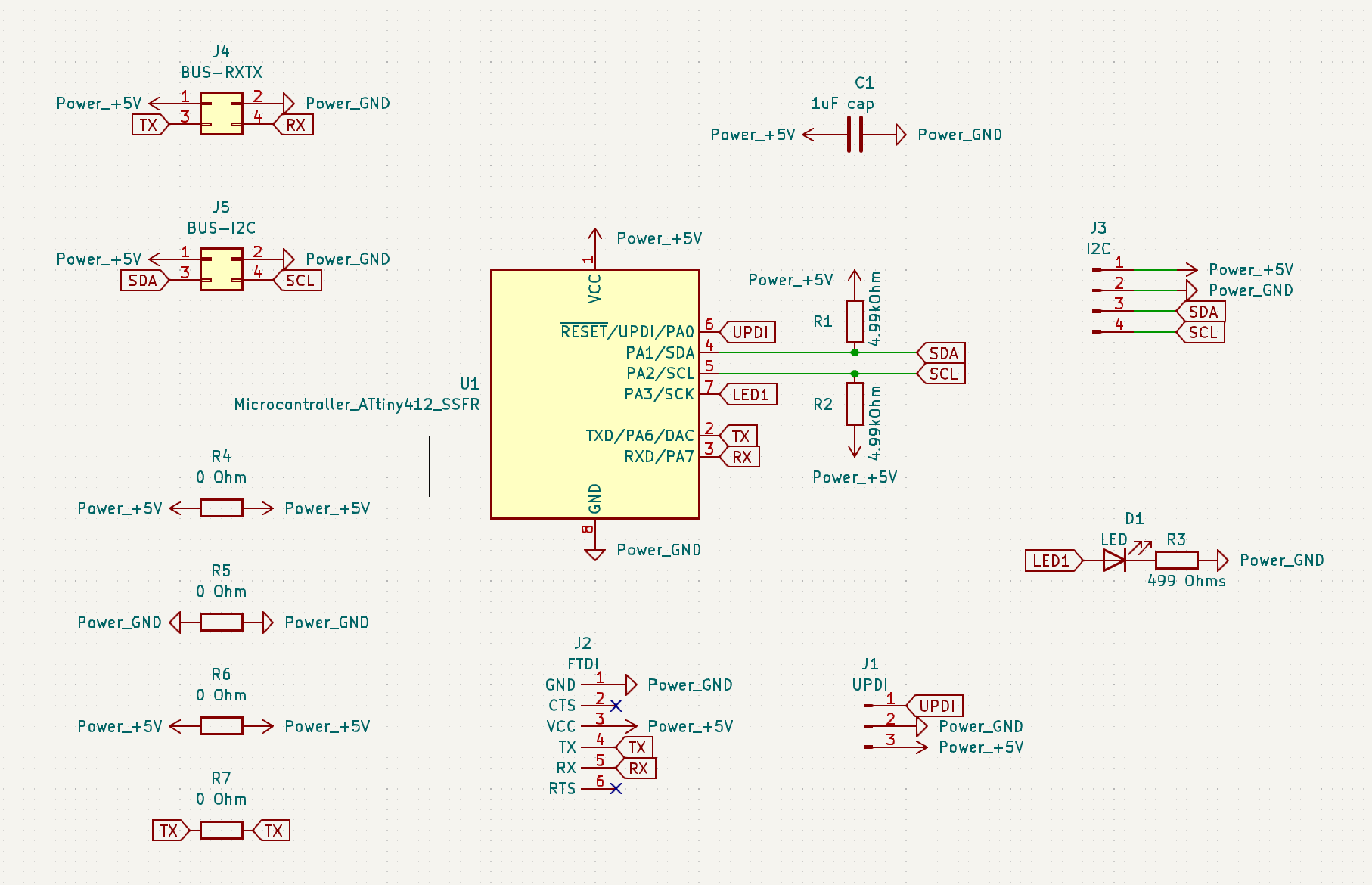
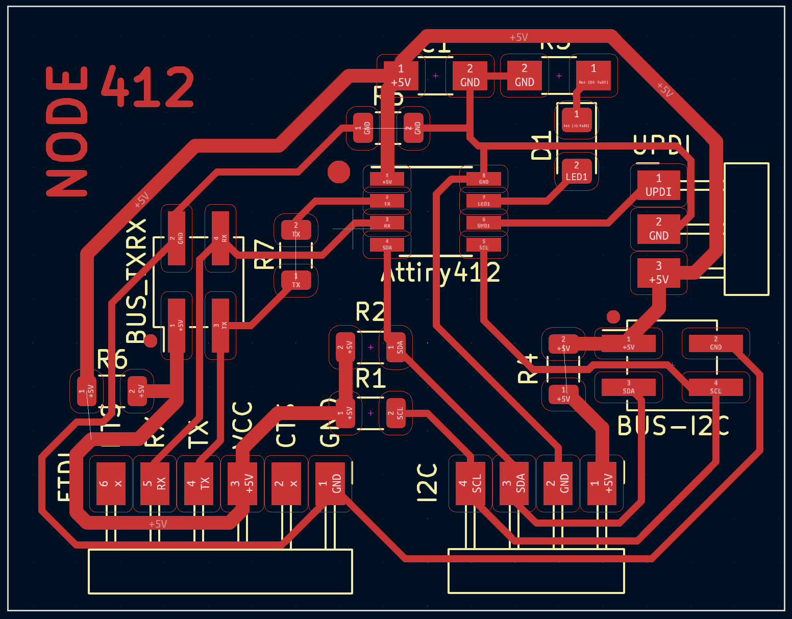
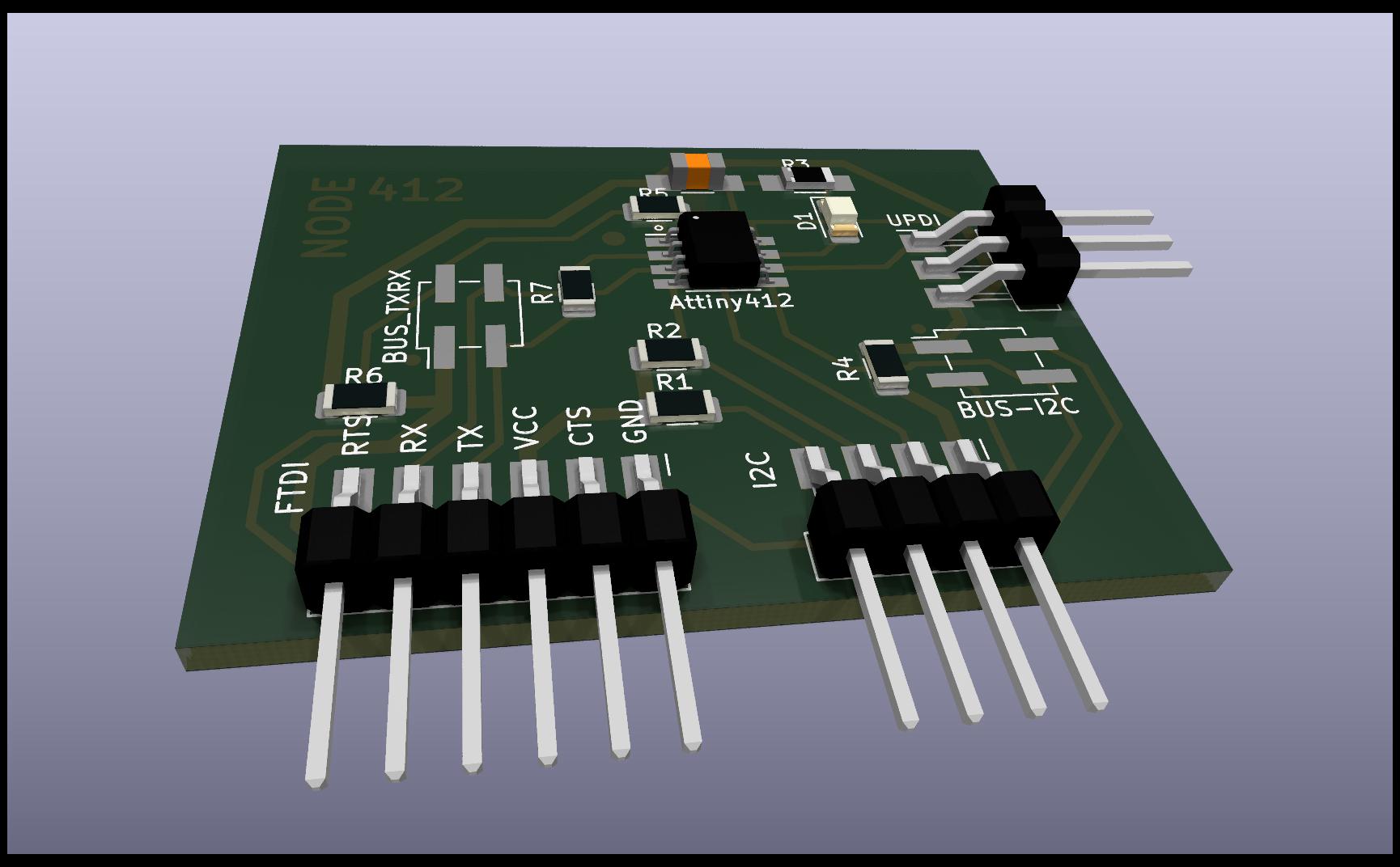
Node Attiny412
The node with Attiny412, I try to use the same bridge design, but adjusted to the size of the new microcontroller.
Attention must be paid, since what was Tx-Rx on the BUS would now be Rx-Tx, since the sender emits through Tx and the nodes listen through Rx.
Node Attiny1614
The node with Attiny1614 is the same as the bridge node, but again you have to be careful, since what was Tx-Rx in the Bridge BUS will now be Rx-Tx, since the sender emits through Tx and the nodes listen by Rx and vice versa.
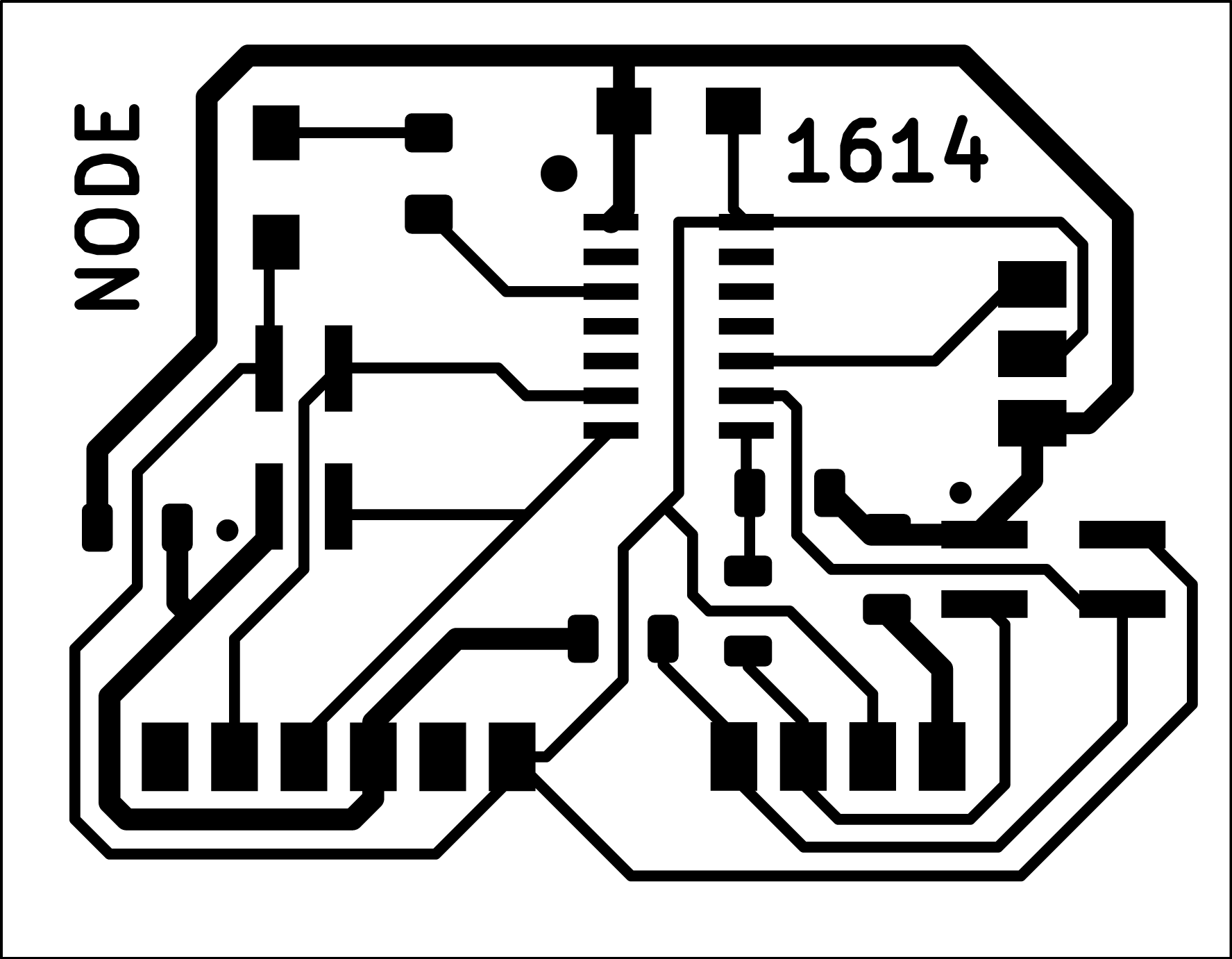
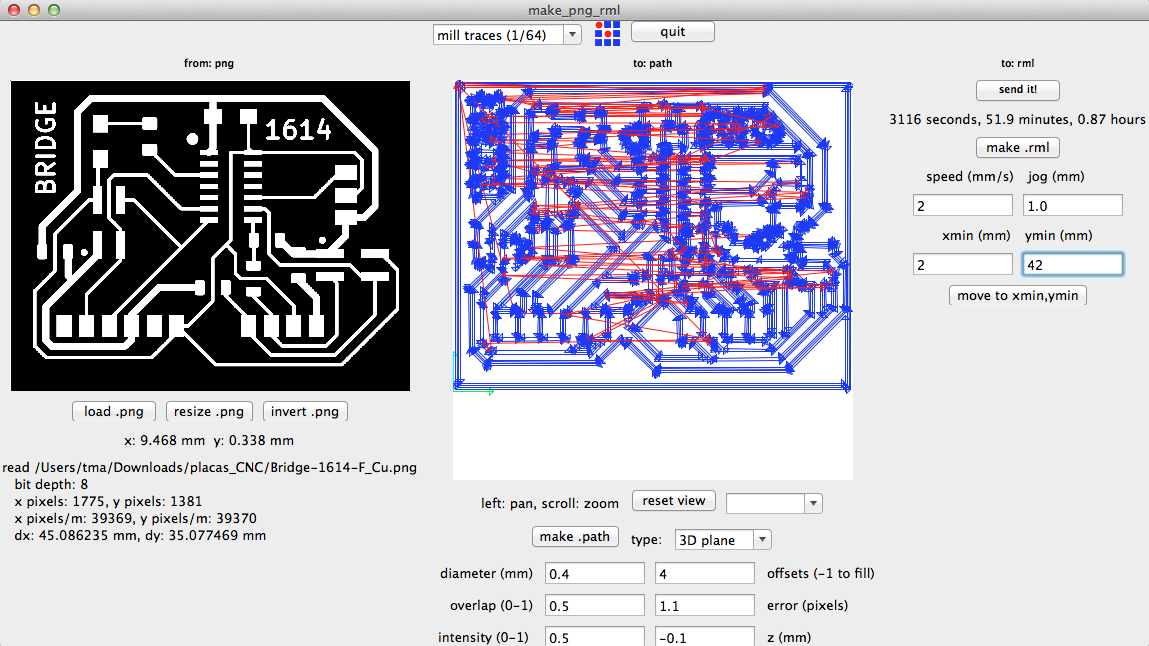
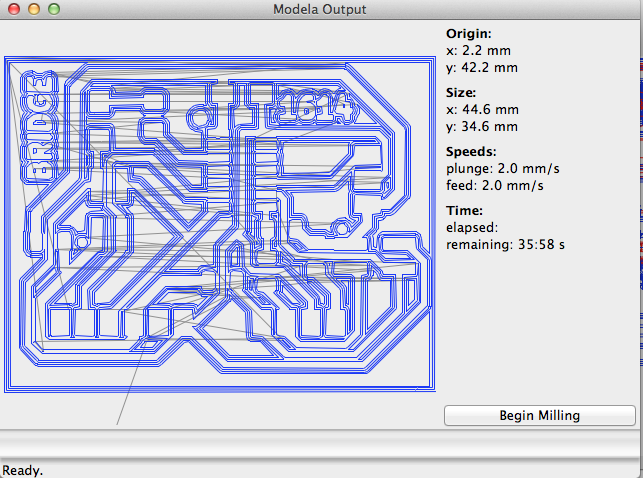
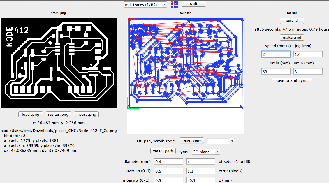
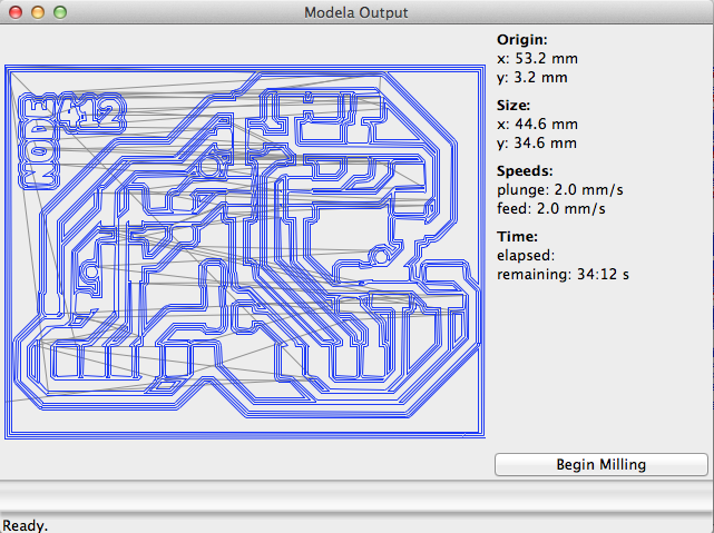
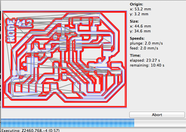
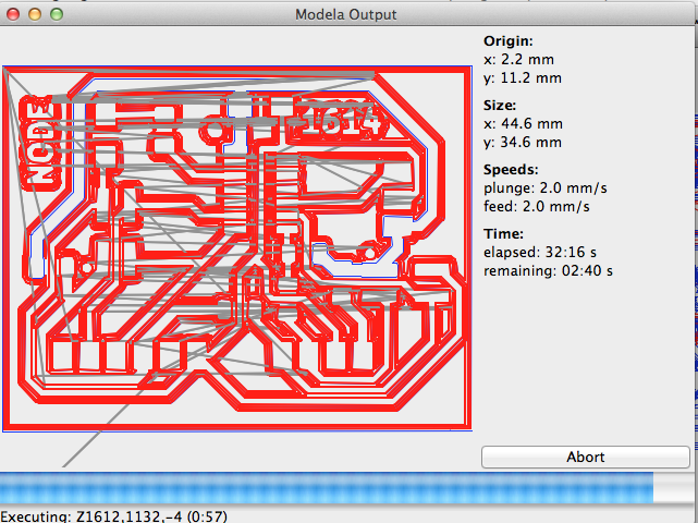
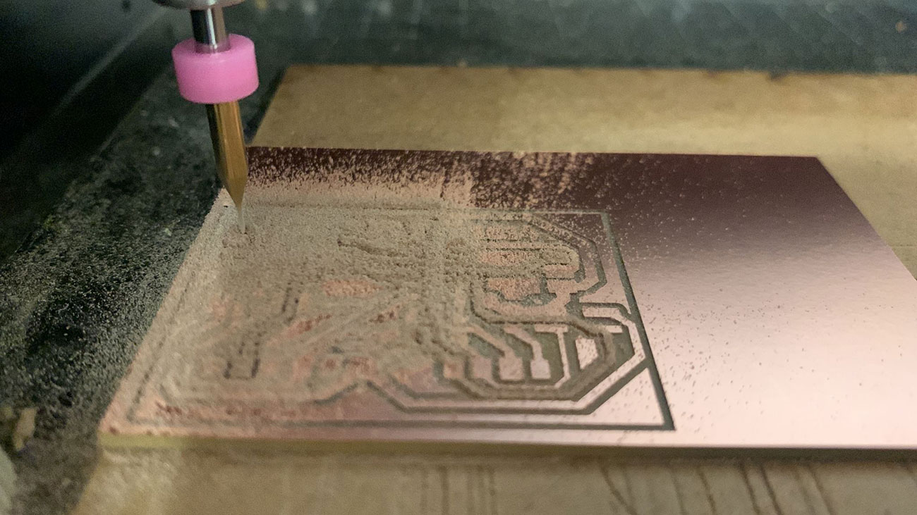
Fab Modules Project
Once the designs are ready, I prepare the milling machine to make the PCBs. This time we use Neil Gershenfeld’s Fab Modules Project, thanks to Nuria Robles for showme how use with the Fab Modules.
Programing TxRx
In order for the two devices to communicate in both directions, two pins are needed, one defined as output or OUPUT that sends its signals to another pin on the other device defined as input or INPUT and vice versa, a pin defined as INPUT capable of “listen” to the impulses that are sent from the transmitter. Pin RX, will be the Receiver pin and pin TX, will be the Transmitter, and logically the cable that joins them will cross from TX to RX and vice versa.
TX: The data sending end, usually plays the role of a transmitter, normally the TXD pin needs to be connected to the RXD pin of other devices. RX : The receiving end of data, usually plays the role of the receiver, normally the RXD pin needs to be connected to the TXD pin of other devices
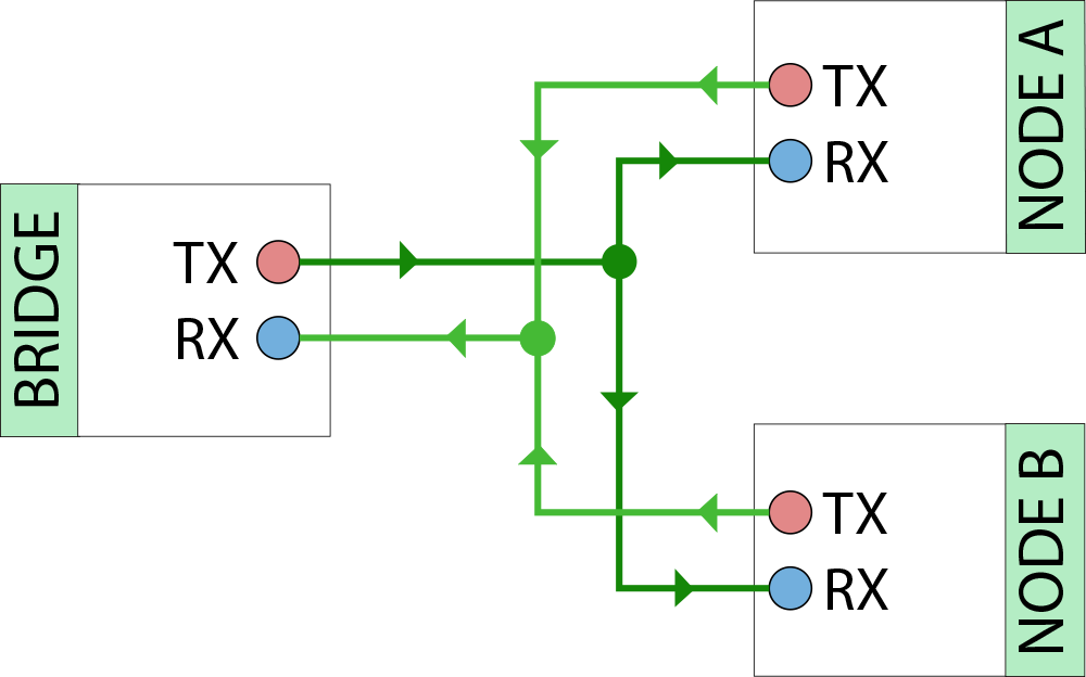
When a device communicates using the serial protocol, its UART transmits on the “TX” line and receives data on the “RX” line. When connecting two devices in this way, one device sends a character using its TX line and the other receives it on its RX line and vice versa.
Once the hardware connections were made, I used arduino IDE to program the BRIDGE first and the nodes after. To program the bridge I firts reviewed some documentation, such as Adrián`s networking assignment. I used Adrián´s code structure but as you can appreciate I made substancial changes, adapting the code to my needs.
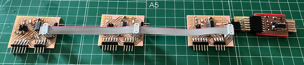
The three boards are connected serially. The Tx of the bridge transmitter board is connected with the Rx of the nodes receivers boards. The Rx of the bridge transmitter boards are connected with the Tx of the nodes receivers boards. The 5V supply and the GND is also connected between the 3 boards.
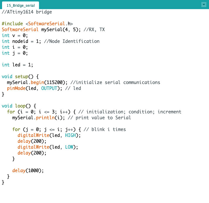
Bridge TxRx
In the case of Adrian’s Bridge he used the Attiny412, in mine it will be with the Attiny1614, so I have to change the pins of the code.
For show the node number of the for statement, i made a blink i+1 times (1, 2, 3, 4).
 Download source code (.ino | .zip)
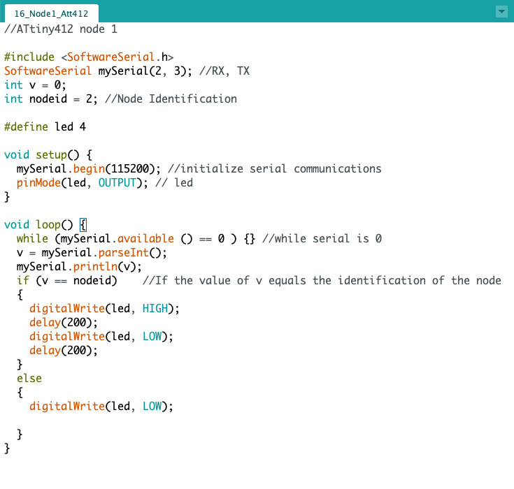
Node 1 TxRx
In this case, after config the pins of serial of Attiny 412, the led blink with recive the value 2 by serial connection.
 Download source code (.ino | .zip)
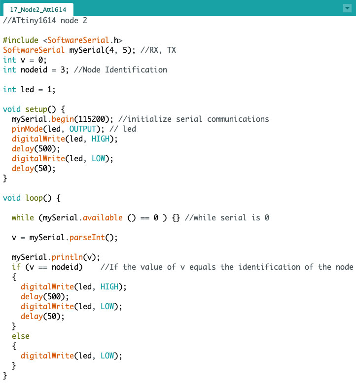
Node 2 TxRx
In this case, after config the pins of serial of Attiny 1614, the led blink with recive the value 3 by serial connection.
 Download source code (.ino | .zip)
Programing I2C
I prepare the ports I2C in any board, and made same sample with I2C comunnication.
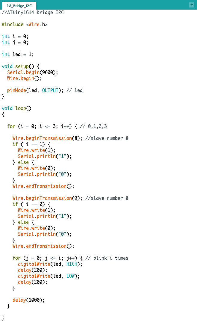
The functionality is similar to the previous example, with a for it generates 4 numbers (0,1,2,3) and if it is number 1 it sends the value to device 8 (node1) or if it is number 2 it sends it to device 9 (node 2). For know the current number i made a blink a blink i+1 times (1, 2, 3, 4).
Bridge I2C
 Download source code (.ino | .zip)
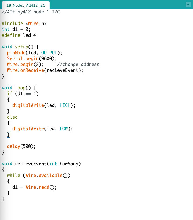
Node 1 I2C
In this case, after config the pins of serial of Attiny 412, the led blink with recive the value 1 by I2C comunication.
 Download source code (.ino | .zip)
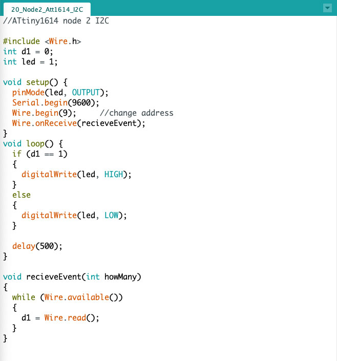
Node 2 I2C
In this case, after config the pins of serial of Attiny 1614, the led blink with recive the value 2 by I2C comunication.
 Download source code (.ino | .zip)
Group Assigment
The link to Group Assignments of Fab Lab León is this
I use Arduino Nano IoT and a M5Stack Fire, a ESP32.
Arduino Nano 33 IoT (Inputs, AP, webserver)
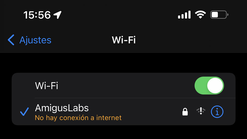
The idea is to simulate a telemetry, in Nano it reads some values from some sensors, and creates a web server and a Wi-Fi access point.
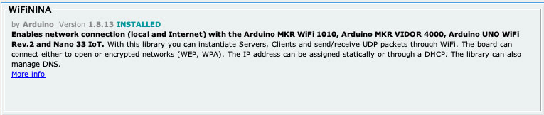
For Arduino Nano 33 IoT i use the library WiFiNINA.
The other devices connected to this Wi-Fi network read the content of a web page, and take it for analytics.
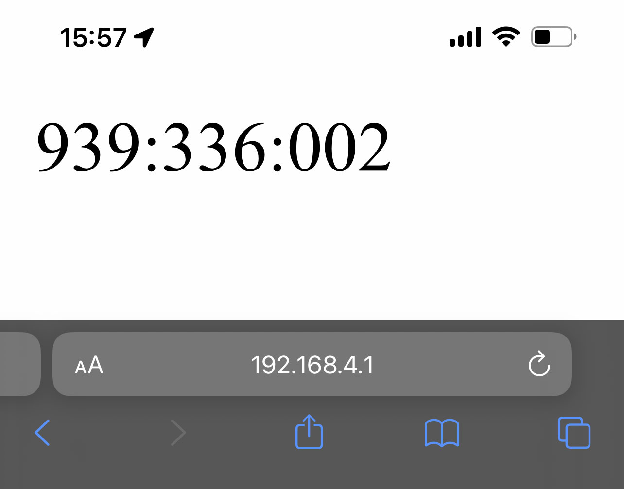
In this case I generate 3 types of variables, which I can read in two ways:
http://192.168.4.1/datos
Returns all three integer values, separated by “:”
Or singler page with a value
http://192.168.4.1/voltaje
http://192.168.4.1/amp
http://192.168.4.1/velocity
In the code can see how made the AP, and the server requests.
In this case the values are made form math formulas. But can replace easy with real values from sensors.
 Download source code (.ino | .zip)
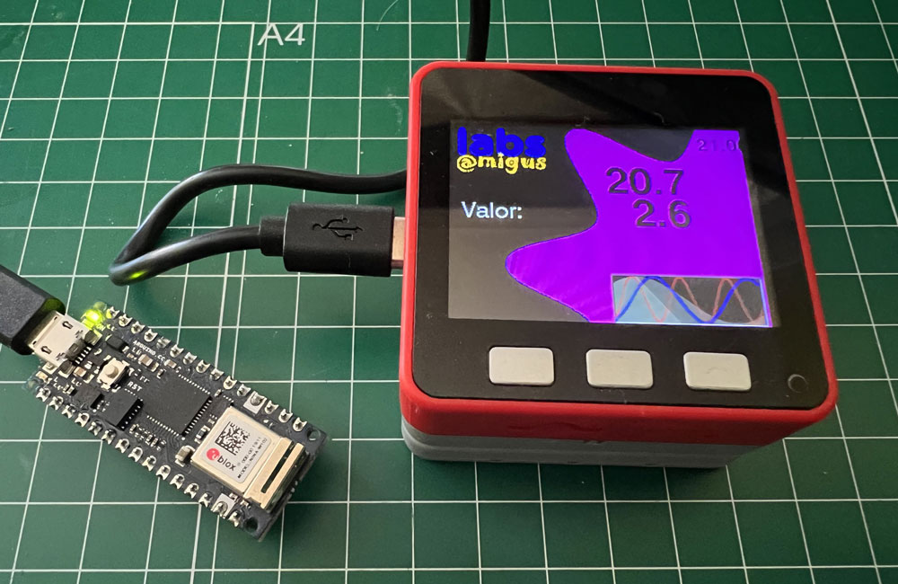
M5Stack Fire (Output)
The M5Stack is a EPS32 with a TFT Color, I will use for connect with Arduino Nano 33 IoT and show the values in the screen.
For get the values in only a call of the server, i get all values separate with : from /datos.
Datos = httpGETRequest(serverNameDatos);

int n = sscanf(Datos.c_str(), "%3s:%3s:%3s", &Vol, &Amp, &Vel);
I get the string and split in variables “Vol”, “Amp” and “Vel”.
Since I converted them to whole numbers, I now apply division to get back the decimals.
VolF = Vol.toFloat() * 0.1;

AmpF = Amp.toFloat() * 0.1;

VelF = Vel.toFloat() * 1.0;
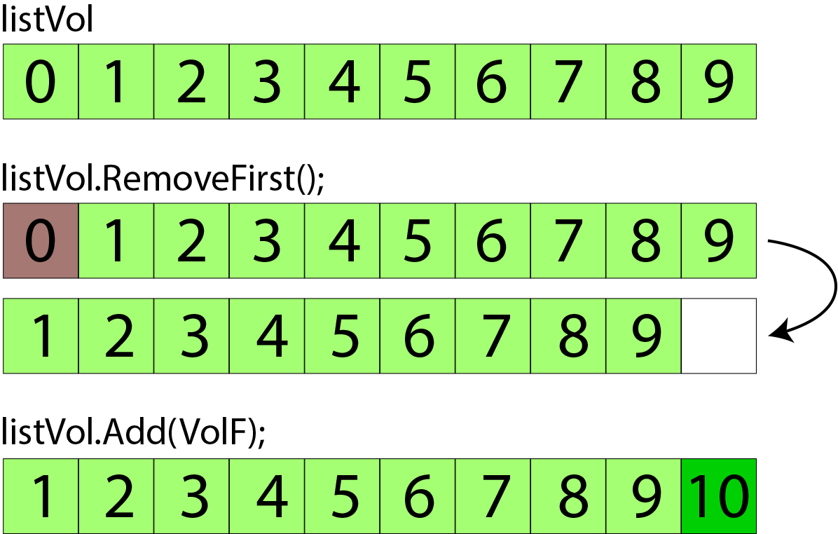
In order to constantly update the graph, I must have the previous values stored in an array.
To solve this, using Luis Llamas’s ListLib.h library (https://github.com/luisllamasbinaburo/Arduino-List) I can make an array of x values, and when I get a new value, remove the first value from the array, and add one to the end of it all.
listVol.RemoveFirst();

listAmp.RemoveFirst();

listVel.RemoveFirst();


listVol.Add(VolF);

listAmp.Add(AmpF);

listVel.Add(VelF);
Since the graph measures 150 pixels, I define my arrays to have 150 values, with the variable int totalList = 150;. You could modify the length simply by varying this value.
In the case of the Voltage and Ampere values, I have a maximum value of 25V and 6A, so I make a mapfloat to have an amplitude in the graph from 0 to 100, although later I will divide it by 2 to have a maximum height of 50px .
VolF = mapfloat(VolF, 0.0, 100.0, 0.0, 25.0);

AmpF = mapfloat(AmpF, 0.0, 100.0, 0.0, 6.0);
 Download source code (.ino | .zip)
Downloads
Explore more like this

17 - Invention, Intellectual Property, and Income
This is the last week before I present the final project, I already have a slide and video proposal of my project.
16 - Applications and Implications
Propose a final project masterpiece that integrates the range of units covered, answering: