3. Computer Aided design
This week I worked on defining my final project idea and started to getting used to the documentation process.
All files used can be found here
Final Project Concept
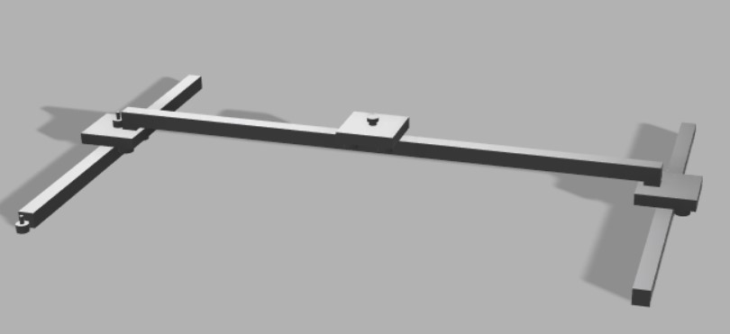
My final project will be a chess board that moves the pieces automatically with an electromagnet underneath with keyboard or button input to select moves. It will also check if the moves are legal and keep track of the positions of the pieces.
3d Design with Fusion 360
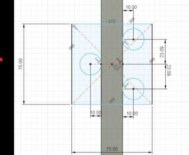
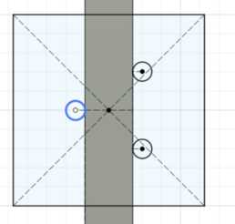
I made a 75x75mm square centered on a midpoint of the width of the bar going across. Then I made a circle of radius 10mm 10mm away from the bar so that it is tangent. I then did the same thing on the other side of the bar with 2 circles offset 40/(3^(1/2))mm to have the centers of the 3 circles form an equilateral triangle.
I extruded the sketch above like so.
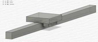
I made a similar platform on the bar going across with some cylinders to model the electromagnet on it.
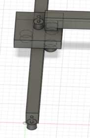
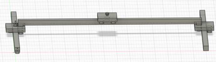
I then made a similar thing on the other side to finish up the general skeleton of the internals.

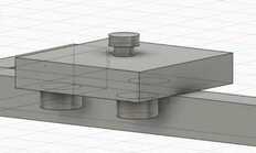
I then made this on one of the platforms to model a motor.
Below is the model with the motors added.
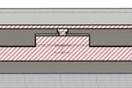
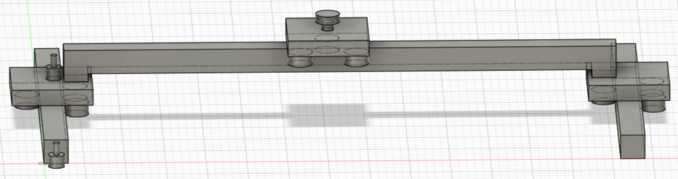
I then made a large rectangular prism around the entire thing to model the rest of the board and shelled it out to have space for the internals.

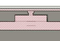
Below shows a cross-section showing where the electromagnet touches the top of the board to move the pieces.
Below is embedded the full design
Parametric 3d Design with Fusion 360
To learn parametric design with Fusion, I read the material on this site. I then repeated the process described above with parametric variables.
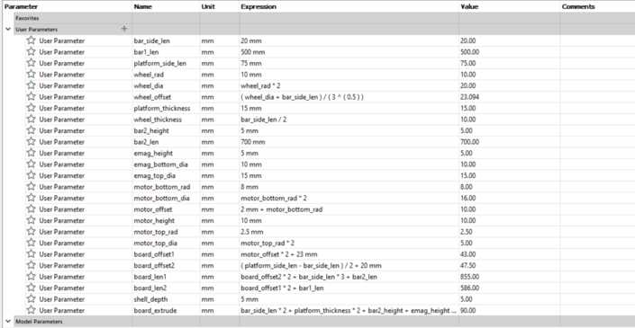
I used the following parameters:
Below is the 2d sketch of the platform

Changing some parameters yields the following:
I then made the platform for the electromagnet

Changing some parameters yields the following:

I then finished the internals, and I used a construction line between the 2 parallel bars defined parametrically to keep everything together when changing parameters.
Changing some parameters yields the following:
I then made a box around the internals representing the board with parametrically defined distance from the internals

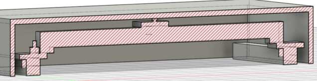
I used section analysis to make sure the electromagnet was touching the board
I then checked to make sure that changing parameters will be fine
With the advice of Yuichi Tamiya, my global evaluator, I also rendered the design. I hid the top box to better show the detail of the internals.
3d Design with Onshape
I started recreating what I had made in fusion on Onshape, but since Onshape does not allow length values to be typed in and specified, I chose to limit it to just making a single platform or the small measurement differences would become too numerous to have a coherent design.
The sketching then extruding process is a lot like fusion, and below is a sketch of a the platform.

I then extruded the sketch, and with extruding, Onshape does allow exact numbers to be typed in

2d Design with Corel Draw
I made a 2d representation of a pawn piece in chess.
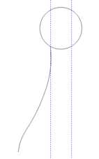
To start, I made a circle with 2 vertical guidelines spaced equally from the circle’s center.

Then I used the b-spline tool to draw 1 side of the pawn from the left guideline
I then duplicated that spline, mirrored it, and moved it to the other guideline. I then drew a horizontal line connecting the 2 sides.
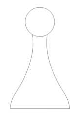
To finish, I used the virtual segment delete tool to take out the section of the circle between the 2 splines.

2d Design with Inkscape
I recreated the 2d representation of a pawn from above in inkscape.
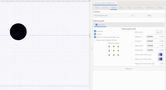
I noticed that it would not let me place lines without a grid to snap to, so I made a grid under file > document properties, and then I made a circle with 2 horizontal guidelines. One through the circle to show 2 points of intersection and another marking the base.
I then drew a b-spline down the left side.
I then duplicated and mirrored the spline and moved it to the right intersection of the guideline and the circle.

To finish, I drew a horizontal line connecting the base.

2d Raster Design with Gimp
I installed gimp from their site and started it up.
I learned a bit of the basics from this video.
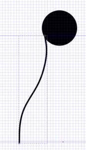
To start, I opened an iconic image of Elon Musk in gimp with file > open.

I then decided to try out the paint tool, and I started drawing a party hat, but part of the way through, I thought it looked more like a volcano, so I made it into a volcano erupting on top of Musk’s head.

I then cropped it and exported it as a jpg with file > export as with the settings displayed below.
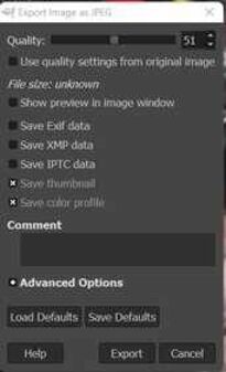
I unchecked the options to keep different data since it seemed to be data that gimp used and I wanted to keep the size of the image as low as possible.

Compressing Multiple Images with Image Magick
Before as documented on the week 2 section on my site, I was using the image magick display, but I then transitioned to using image magick on the command line.
At first to convert pngs to jpgs and compress them, I used the following command from the Image Magick site:
magick fileName.png -resize 50% -quality 50 fileName.jpg
Then I searched how to do the same to multiple files and found this site and ran the following commands:
mkdir newFolder
magick mogrify -format jpg -resize 50% -quality 50 -path ./newFolder *.png