Final Project
Slide

Updated video
Video presented during oral presentation
Final files
All final design files can be found here
All final code files can be found here
Concept
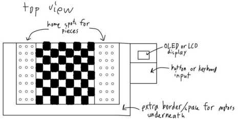
My final project will be a chess board that moves the pieces automatically with an electromagnet underneath with keyboard or button input to select moves. It will also check if the moves are legal and keep track of the positions of the pieces.
Sketches
The following are sketches of a possible design. Details about them can be found on my week 1 assignment page.
Top View
Mechanism
Piece Design

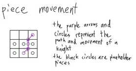
Piece Movement
2D and 3D Modeling
The following are 3d models of a possible design. Details about them can be found on my week 3 assignment page.
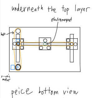
Internals
Under Board View

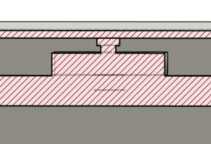
Electromagnet Section Analysis
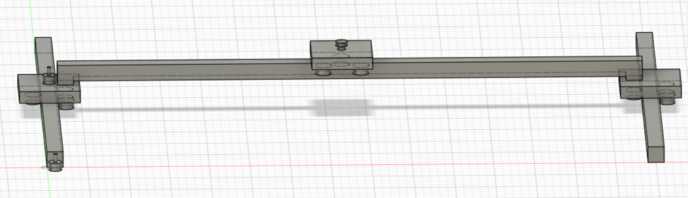
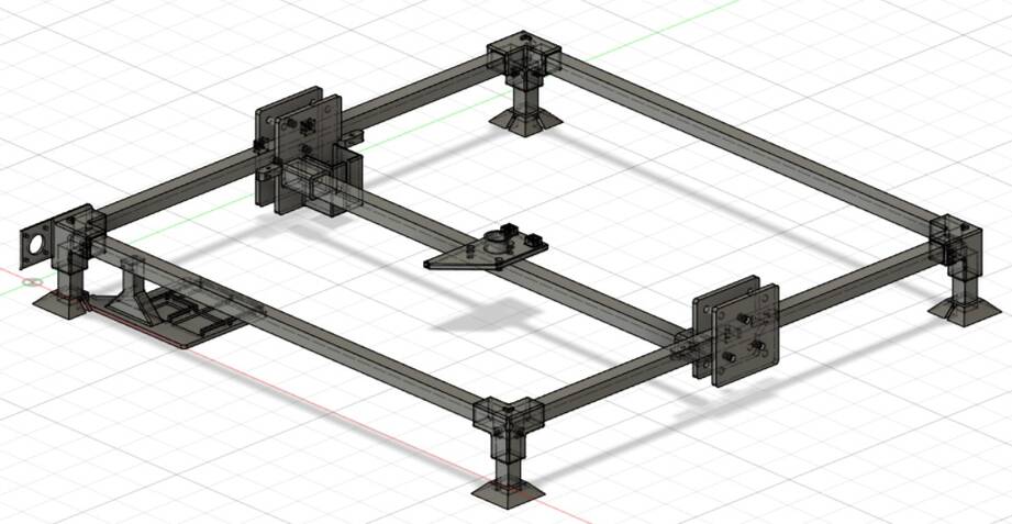
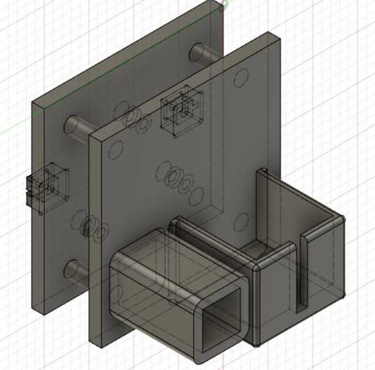
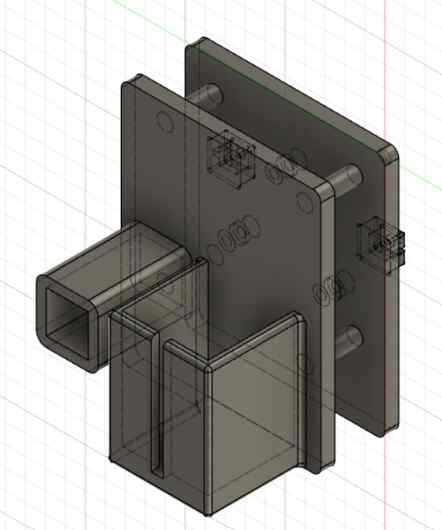
Updated 3d model
I used the gantry design files that I made that are further down in my documentation to make this 3d model of the gantry mechanism, which is the main mechanical and physical aspect of my project.
Output
I used a stepper motor to contribute to my final project during output devices week to control the movement of the gantry moving the electromagnet under the board. I wrote a stepper motor class utilizing baremetal elements with writing to the registers instead of using digital write, which can be found here. Below is a video of the stepper motor working.
Input
I used a 3d hall effect sensor to contribute to my final project during input devices week to either continuously track the movement of the electromagnet (when it’s on) or to zero the gantry depending on both the range of the sensor and the size of the board. I also wanted to learn how to use this sensor for future applications as well. Code for reading from the sensor and writing to serial can be found here. Below is a video of the sensor working.
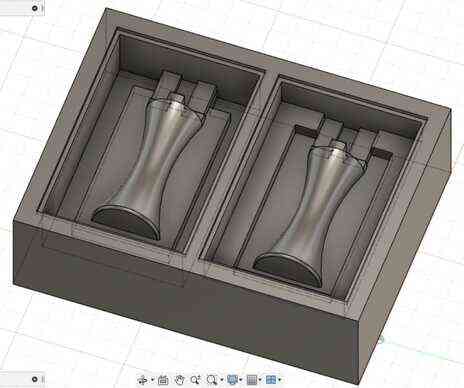
Piece molds
I ended up 3d printing the molds due to the fact that as documented on my week 10 page, my designs could not be milled out with the bits available without a collision with the stock.
Rook
I used the failed design from my week 10 documentation and changed some parameters and moved the vents since I would need the bottom to place magnets to be insert molded to be attracted by the electromagnet.
I printed it and poured moldstar 20T to create the flexible 2 part mold.
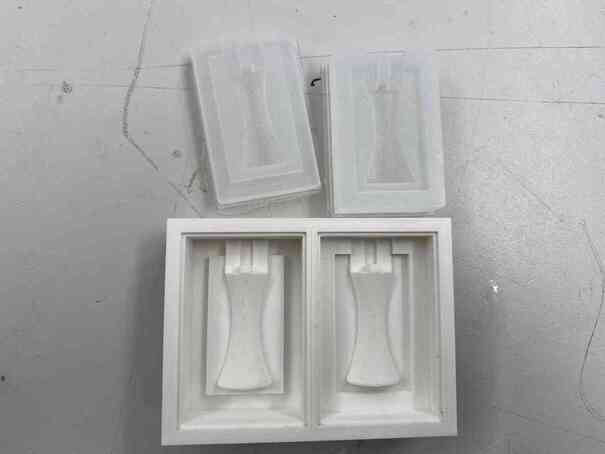
I then tested the mold without insert molding anything by pouring smoothcast 65D and fastening the 2 parts together with rubber bands.
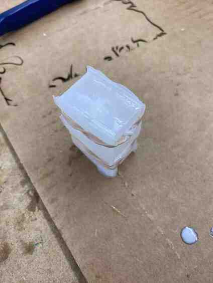
I then cleaned off the excess and cut away the extrusions created by the vents, and it turned out well.
Later, after talking with Dr. Gershenfeld, I looked at this documentation by Shaun Salzberg and saw a better way to insert mold the magnets by having the bottom of the piece open and putting a stick with the magnet attatched to it accross. I adjusted the method a bit by having another magnet on the opposite side of the stick hold the magnet in place instead of using tape. I also changed some parameters to make it smaller.
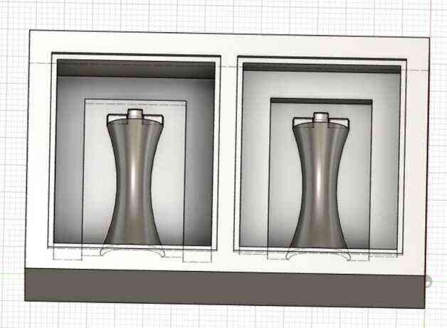

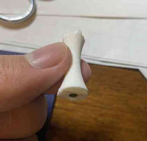
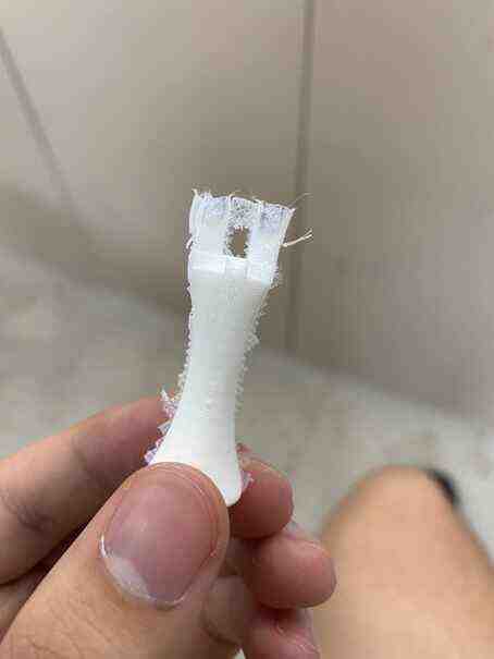
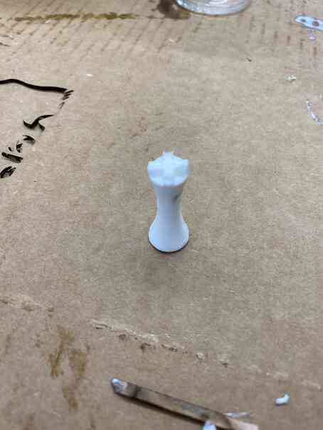
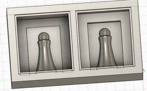
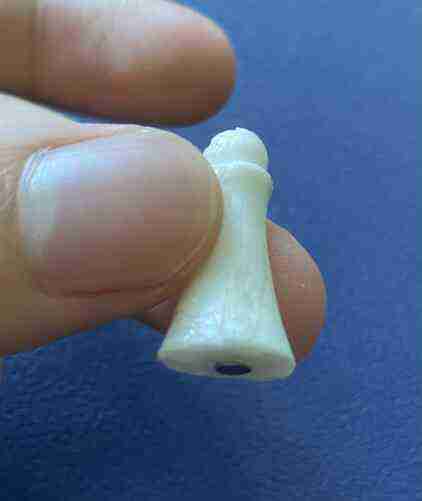
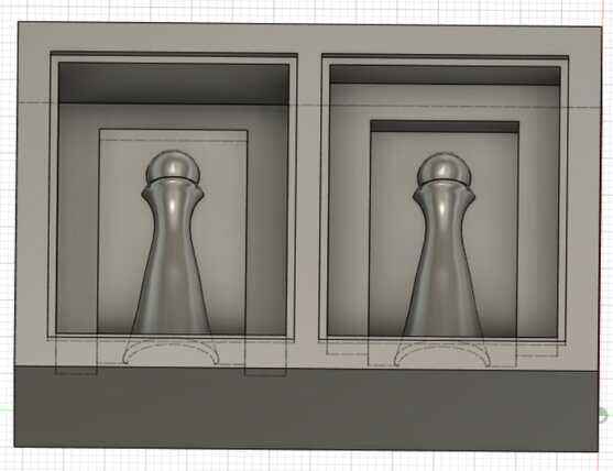
Pawn
I started by making the full pawn piece with circles and the loft tool as well as a sphere and fillets.
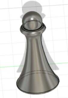
I then made a box around it with just half the piece, duplicated it, and added the corresponding lips to fit together on each.
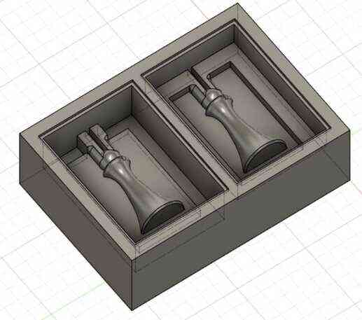
Like with the rook above, I changed the method of insert molding the magnet and made it smaller.
Bishop
For the bishop, since it looks similar enough to a pawn, I just copied my pawn design and changed some parameters to make it taller.

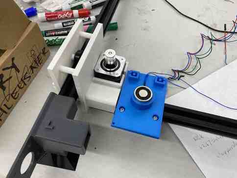
Solenoid
I started off testing the solenoid with an arduino connected with a motor driver and turned the electromagnet on, and it worked quite nicely. My instructor, Dr. Fagan, advised me to embed permanent magnets into the bottom of my pieces instead of just metal discs as I had planned to before, and I tested how that would move with a piece by tapping it to the bottom of the piece I molded and testing with cardboard, and it worked nicely.
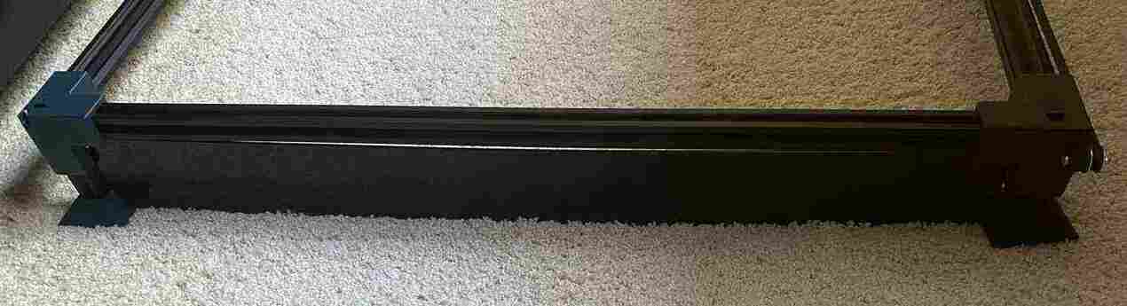
Gantry
The following are the various pieces of the gantry including the carriages, corner pieces, and base pieces.
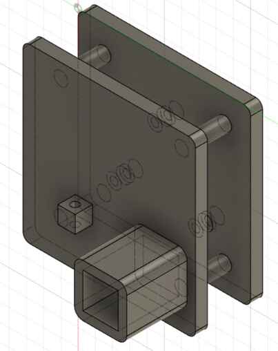
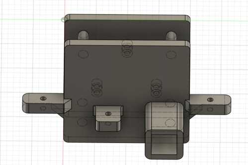
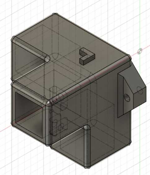
Y axis carriage
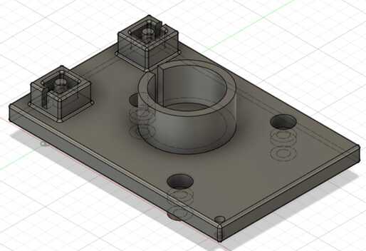
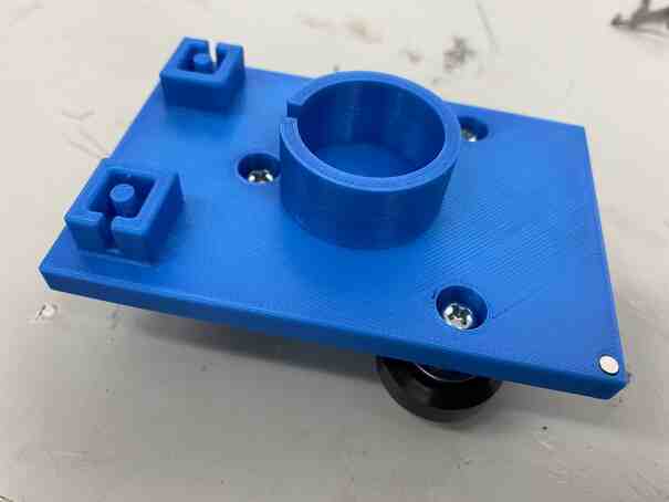
I started with a basic parametric design with 3 holes in an equilateral triangle for the v slot rollers that will be bolted on, a case for the electromagnet with a slot for the wires, and belt slots that I designed for my machine week group.
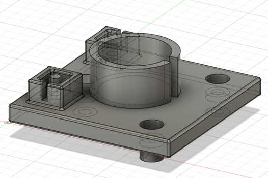
After getting done with the other pieces and changing some parameters, I found that I would have to extend the belt slots out, but I had made the platform a square, so to avoid having to redesign most of it, I made another parameter to set an extension amount that would be extruded from the square. I also elevated the belt slots a bit so that the side of the belt that does not attach does not drag on the piece if it touches. I also added a hole on the corner for permanent magnets to aid in zeroing with the 3d hall effect sensor.

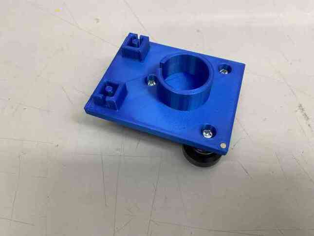
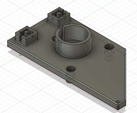
I then realized that the magnet was too close to the v slot rollers, so I wouldn’t be able to mount the 3d hall effect sensor very close to it in its zeroed position, so I made an extension in that direction as well.
Due to the addition of the wings on the x axis carriages, the magnets for zeroing on this no longer lined up with the hall effect sensor, so I extended it more.

I also took the opportunity to add a chamfer to reduce print time and filament usage.
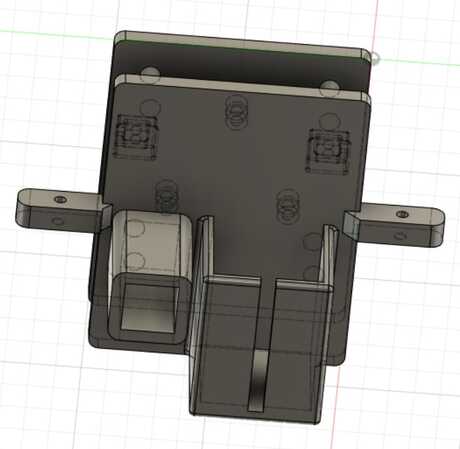
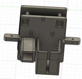
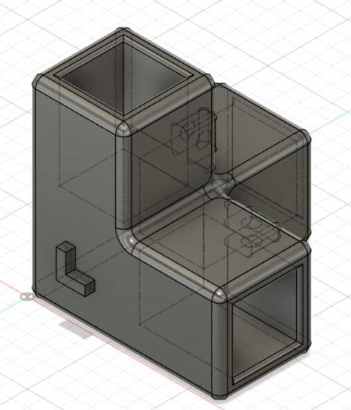
X axis carriage with stepper motor
The design for this went quite smoothly. I copied the y axis carriage, removed all the unnecessary parts, and added another platform that would extend to the other side of the aluminium extrusion and hold the y axis carriage and a stepper motor.
I then realized that the stepper motor was too high and would not align with the y axis belt slot and would jam into the top chess board.
So I lowered it by changing some parameters and also adjusted the design a small bit to fit it. I also took the chance to add a fillet that I had previously forgotten.
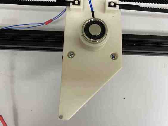
Even after adding the horizontal rollers on the other side of the x axis as described below, the gantry was still binding. I suspected that this was because the y axis going across the 2 carriages was not centered and changed the way the forces interacted to keep things straight with just rollers on a single side, so I added them on this side as well to make sure all unwanted degrees of freedom were eliminated.
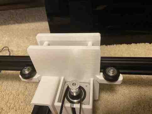
As I was in a rush with this design, I had not aligned the wings properly, but it still fit on the gantry and made the gantry move well, eliminating that degree of freedom. To make it run more smoothly and to utilize best practices, I remedied the design and reprinted yet again.

X axis carriage with pulley
For this, I copied the other x axis carriage, replaced the stepper motor mount with a pulley mount, and mirrored it.
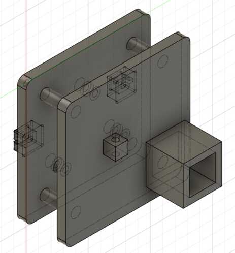
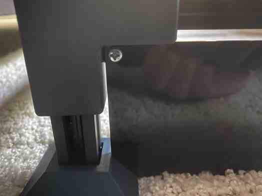
I adjusted this as well to fit my realization of the stepper being too high, and I also took the opportunity to increase the length of the y axis mount and make it closer to the exact size of the aluminium extrusions since I was noticing that it would lag behind in movement when the other side was moved in the gantry.

Even after this, the gantry was still binding while moving along the x axis, so I asked my teacher, Mr. Budzichowski, for advice, and he recommended that I tighten everything up since the entire machine was loose and that I add horizontal rollers to this piece to eliminate the degree of freedom that allows for rotation of the carriage and keep everything straight as a result.
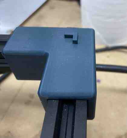
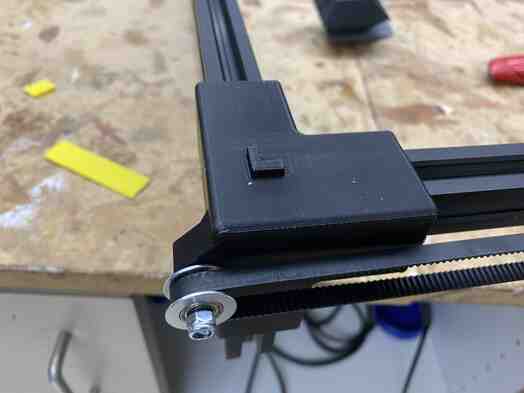
Corner piece
This design went quite smootly with just holes for the aluminium extrusions, a corner part on top to align the board, and holes for bolts to attach acrylic walls.

When testing with the aluminium extrusions, however, I realized that I had too much space in addition to the exact dimensions, and it was wobbly, so I changed a parameter to account for that and reprinted. Mr. Budzichowski recommended that I make the corners have the exact size of the extrusions and have a slight fillet on the entrance to make the pieces go in easier.
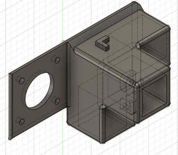
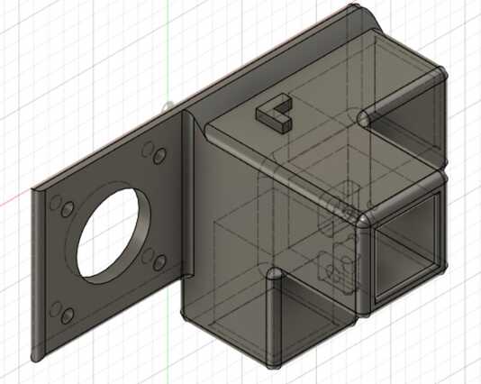
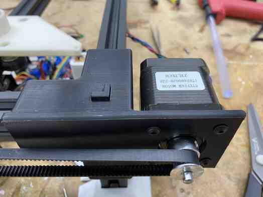
Corner piece with stepper motor
I used the corner design above and just added a stepper motor mount to it.

After printing it and the pulley mount, I realized that they were both mirrored with respect to the x axis carriage, so I mirrored both of them.

When testing with the aluminium extrusions, however, I realized that I had too much space in addition to the exact dimensions, and it was wobbly, so I changed a parameter to account for that and reprinted along with the fillet mentioned above. I also made the mount slightly thicker just in case.
Corner piece with pulley
Like the corner with the stepper motor, I copied the corner design and added a pulley mount to it.

As stated above, I realized this was mirrored after printing, so I corrected that.
When testing with the aluminium extrusions, however, I realized that I had too much space in addition to the exact dimensions, and it was wobbly, so I changed a parameter to account for that and reprinted along with the fillet mentioned above.

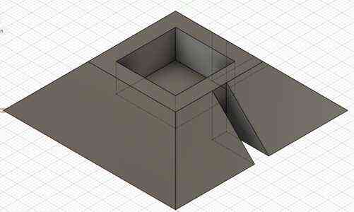
Base piece
This was designed so that the aluminium extrusions giving vertical height would go into them and be stable from the pyramid and has slots for the acrylic walls to fit into.
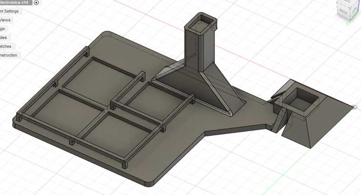
Base with electronics mounts
I copied the base piece, and on the internal section, I added mounts for the electronics (main board, input board, and motor drivers). I also had arches to have some wire management although for this first iteration they don’t have any sections in them; some specific wire sections and routes may be added later after putting things on this and seeing where everything would go.
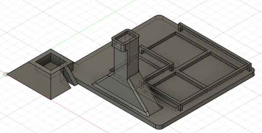
After assembling an early version of the gantry, however, I noticed that the stepper motor was colliding with the motor driver and the headers.

I moved all the electronics inwards more to avoid the stepper.
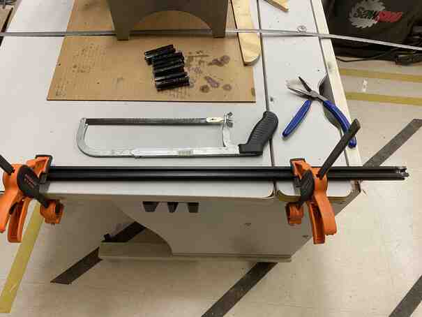
Cutting aluminium extrusions
Once the aluminium extrusions came in, I had to cut some down to the right sizes. I used the metal band saw, which I had some experience with from machine week. This time, my instructor, Mr. Dubick, recommended that I set up a jig since I needed 4 identical length pieces for some of my cuts.
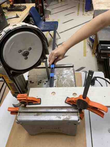
While I was cutting the final piece, however, the blade broke, so I had to use a hacksaw to finish.
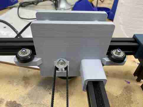
Test
I uploaded the same code used to test my electronics below with the stepper motors mounted to test the gantry, and it worked quite well.
Electronics
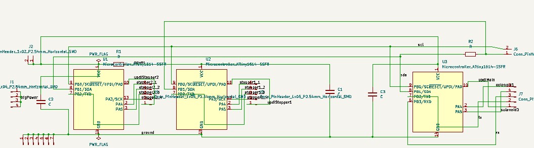
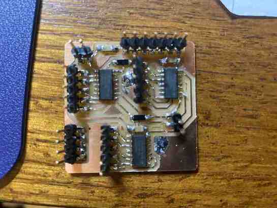
Main board
This contains 3 attiny1614s networked together with i2c with one main that also controls the solenoid directly and 1 for each of the 2 stepper motors. I put all 3 on the same board to eliminate extra jumpers and to make sharing ground, power, and an i2c bus easier.

Main board tests
I did an initial test using code very similar to my code from networking week.
Thinking the problem was with the motor driver, I swapped the chips controlling each motor driver and realized that it was a problem with one of the microcontrollers.
To confirm, I used a multimeter to probe the pins of the 1614, and it seemed like PA4 was permanently set to low and was not responding to any code, so I took it off the board and used a different 1614 and that worked.
The arduino was purely to provide power, and the 2 secondary 1614s were each connected to a stepper motor with the main board sending them each instructions. The following was the code uploaded to each board:
Main board
#include <Wire.h>
#define XSTEPPER 0x09
#define YSTEPPER 0x0A

void setup() {
  // put your setup code here, to run once:
  Wire.begin();
  PORTB.PIN0CTRL |= 1 << 3;
  PORTB.PIN1CTRL |= 1 << 3;
  Wire.setClock(400000);
}

void loop() {
  // put your main code here, to run repeatedly:
  sendSteps(200, XSTEPPER);
  sendSteps(200, YSTEPPER);
  delay(500);
  sendSteps(-200, XSTEPPER);
  sendSteps(-200, YSTEPPER);
  delay(500);
}

void sendSteps(const int& steps, const byte address) {
  if (steps < 0) {
    for (int i = 0; i < steps * -1; ++i) {
      Wire.beginTransmission(address);
      int8_t val = -1;
      Wire.write(val);
      Wire.endTransmission();
      delay(10);
    }
  } else {
    for (int i = 0; i < steps; ++i) {
      Wire.beginTransmission(address);
      int8_t val = 1;
      Wire.write(val);
      Wire.endTransmission();
      delay(10);
    }
  }
}
Secondary board 1
#include <Wire.h>

#define ADDRESS 0x09

class Stepper {
  private:
  int pin1shift, pin2shift, pin3shift, pin4shift;
  volatile byte& reg1;
  volatile byte& reg2;
  volatile byte& reg3;
  volatile byte& reg4;
  int stepPos;
  int delayTime;

  public:
  Stepper(volatile byte& r1, int p1, volatile byte& r2, int p2, volatile byte& r3, int p3, volatile byte& r4, int p4, int del): pin1shift(p1), reg1(r1), pin2shift(p2), reg2(r2), pin3shift(p3), reg3(r3), pin4shift(p4), reg4(r4), delayTime(del) {
    stepPos = 0;
  }

  private:
  void out1() {
    reg1 |= 1 << pin1shift;
  }

  void clear1() {
    reg1 &= ~(1 << pin1shift);
  }

  void out2() {
    reg2 |= 1 << pin2shift;
  }

  void clear2() {
    reg2 &= ~(1 << pin2shift);
  }

  void out3() {
    reg3 |= 1 << pin3shift;
  }

  void clear3() {
    reg3 &= ~(1 << pin3shift);
  }

  void out4() {
    reg4 |= 1 << pin4shift;
  }

  void clear4() {
    reg4 &= ~(1 << pin4shift);
  }

  void runStep() {
    switch (stepPos) {
      case 0:
      out1();
      clear2();
      out3();
      clear4();
      break;
      case 1:
      clear1();
      out2();
      out3();
      clear4();
      break;
      case 2:
      clear1();
      out2();
      clear3();
      out4();
      break;
      case 3:
      out1();
      clear2();
      clear3();
      out4();
      break;
    }
    delay(delayTime);
  }

  public:
  void stepCW(int numSteps) {
    for (int i = 0; i < numSteps; ++i) {
      stepPos = (stepPos + 1) % 4;
      runStep();
    }
  }

  void stepCCW(int numSteps) {
    for (int i = 0; i < numSteps; ++i) {
      --stepPos;
      if (stepPos < 0) stepPos = 3;
      runStep();
    }
  }
};

void setup() {
  // put your setup code here, to run once:
  Wire.begin(ADDRESS);
  PORTA.DIRSET |= 1 << 4;
  PORTA.DIRSET |= 1 << 5;
  PORTA.DIRSET |= 1 << 3;
  PORTB.DIRSET |= 1 << 2;
  Wire.onReceive(doStep);
}

Stepper myStepper(PORTA.OUT, 4, PORTA.OUT, 5, PORTB.OUT, 2, PORTA.OUT, 3, 0);

void loop() {
  // put your main code here, to run repeatedly:
  delay(10);
}

void doStep(int numBytes) {
  int8_t steps = Wire.read();
  if (steps < 0) myStepper.stepCCW(1);
  else myStepper.stepCW(1);
}
Secondary board 2
#include <Wire.h>

#define ADDRESS 0x0A

class Stepper {
  private:
  int pin1shift, pin2shift, pin3shift, pin4shift;
  volatile byte& reg1;
  volatile byte& reg2;
  volatile byte& reg3;
  volatile byte& reg4;
  int stepPos;
  int delayTime;

  public:
  Stepper(volatile byte& r1, int p1, volatile byte& r2, int p2, volatile byte& r3, int p3, volatile byte& r4, int p4, int del): pin1shift(p1), reg1(r1), pin2shift(p2), reg2(r2), pin3shift(p3), reg3(r3), pin4shift(p4), reg4(r4), delayTime(del) {
    stepPos = 0;
  }

  private:
  void out1() {
    reg1 |= 1 << pin1shift;
  }

  void clear1() {
    reg1 &= ~(1 << pin1shift);
  }

  void out2() {
    reg2 |= 1 << pin2shift;
  }

  void clear2() {
    reg2 &= ~(1 << pin2shift);
  }

  void out3() {
    reg3 |= 1 << pin3shift;
  }

  void clear3() {
    reg3 &= ~(1 << pin3shift);
  }

  void out4() {
    reg4 |= 1 << pin4shift;
  }

  void clear4() {
    reg4 &= ~(1 << pin4shift);
  }

  void runStep() {
    switch (stepPos) {
      case 0:
      out1();
      clear2();
      out3();
      clear4();
      break;
      case 1:
      clear1();
      out2();
      out3();
      clear4();
      break;
      case 2:
      clear1();
      out2();
      clear3();
      out4();
      break;
      case 3:
      out1();
      clear2();
      clear3();
      out4();
      break;
    }
    delay(delayTime);
  }

  public:
  void stepCW(int numSteps) {
    for (int i = 0; i < numSteps; ++i) {
      stepPos = (stepPos + 1) % 4;
      runStep();
    }
  }

  void stepCCW(int numSteps) {
    for (int i = 0; i < numSteps; ++i) {
      --stepPos;
      if (stepPos < 0) stepPos = 3;
      runStep();
    }
  }
};

void setup() {
  // put your setup code here, to run once:
  Wire.begin(ADDRESS);
  PORTA.DIRSET |= 1 << 4;
  PORTA.DIRSET |= 1 << 5;
  PORTA.DIRSET |= 1 << 3;
  PORTB.DIRSET |= 1 << 2;
  Wire.onReceive(doStep);
}

Stepper myStepper(PORTA.OUT, 4, PORTA.OUT, 5, PORTB.OUT, 2, PORTA.OUT, 3, 0);

void loop() {
  // put your main code here, to run repeatedly:
  delay(10);
}

void doStep(int numBytes) {
  int8_t steps = Wire.read();
  if (steps < 0) myStepper.stepCCW(1);
  else myStepper.stepCW(1);
}
I then tested the input board by connecting it to the i2c pins on the main board as well as ground and power. This time instead of using an arduino to provide power, I used an ftdi chip and also connected it to serial of the main board testing it in the process as well, and it all worked nicely. One thing I noticed due to the long delays between input requests though is that it seems like the input board only updates the readings after a request is made to it, so I will have to account for that by first making a request that updates it and immediately making another request to get the actual updated data.
It used the following code in the main board and the same code in the secondary boards as above:
#include <Wire.h>
#define INPUTADR 0x35
#define XSTEPPER 0x09
#define YSTEPPER 0x0A

void setup() {
  // put your setup code here, to run once:
  Serial.begin(9600);
  Wire.begin();
  PORTB.PIN0CTRL |= 1 << 3;
  PORTB.PIN1CTRL |= 1 << 3;
  Wire.setClock(400000);
   //
   // reset TLE493D
   //
   Wire.beginTransmission(INPUTADR);
   Wire.write(0xFF);
   Wire.endTransmission();
   Wire.beginTransmission(INPUTADR);
   Wire.write(0xFF);
   Wire.endTransmission();
   Wire.beginTransmission(INPUTADR);
   Wire.write(0x00);
   Wire.endTransmission();
   Wire.beginTransmission(INPUTADR);
   Wire.write(0x00);
   Wire.endTransmission();
   delayMicroseconds(50);
   //
   // configure TLE493D
   //
   Wire.beginTransmission(INPUTADR);
   Wire.write(0x10);
   Wire.write(0x28);
      // config register 0x10
      // ADC trigger on read after register 0x05
      // short-range sensitivity
   Wire.write(0x15);
      // mode register 0x11
      // 1-byte read protocol
      // interrupt disabled
      // master controlled mode
   Wire.endTransmission();
}

void loop() {
  // put your main code here, to run repeatedly:
  sendSteps(200, XSTEPPER);
  sendSteps(200, YSTEPPER);
  delay(500);
  sendSteps(-200, XSTEPPER);
  sendSteps(-200, YSTEPPER);
  delay(500);

  uint8_t data[6];
  int transformedData[3];
  Wire.requestFrom(INPUTADR, 6);
  for (int i = 0; i < 6; ++i) {
    data[i] = Wire.read();
  }
  transformedData[0] = (data[0] << 4)+((data[4] & 0xF0) >> 4);
  transformedData[1] = (data[1] << 4)+(data[4] & 0x0F);
  transformedData[2] = (data[2] << 4)+(data[5] & 0x0F);
  for (int i = 0; i < 3; ++i) {
    if (transformedData[i] > 2047) transformedData[i] -= 4096;
    Serial.print(transformedData[i]);
    Serial.print(' ');
  }
  Serial.print('\n');
  delay(500);
}

void sendSteps(const int& steps, const byte address) {
  if (steps < 0) {
    for (int i = 0; i < steps * -1; ++i) {
      Wire.beginTransmission(address);
      int8_t val = -1;
      Wire.write(val);
      Wire.endTransmission();
      delay(10);
    }
  } else {
    for (int i = 0; i < steps; ++i) {
      Wire.beginTransmission(address);
      int8_t val = 1;
      Wire.write(val);
      Wire.endTransmission();
      delay(10);
    }
  }
}
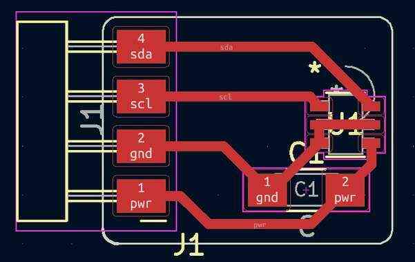
Input board
Since my input needs to be moved out more towards the gantry to be close to the zero point, I made a separate board for it along with the fact that if the magnets get near the microcontrollers it would wipe them.
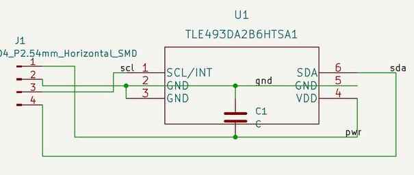
During the pcb design stage, I wanted to made the center of the magnetic field measurements to correspond with the center of the board, so I used some guidelines to help with that.
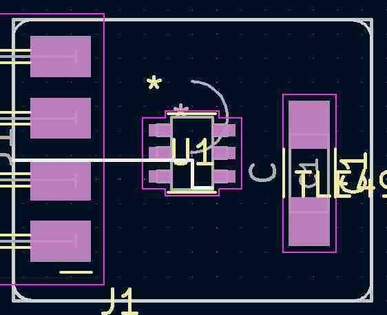

For the headers, I decided to solder them on pointing downwards so that it would be easier to route the wires with a hole in the mount for them that would position it close to the zero position.
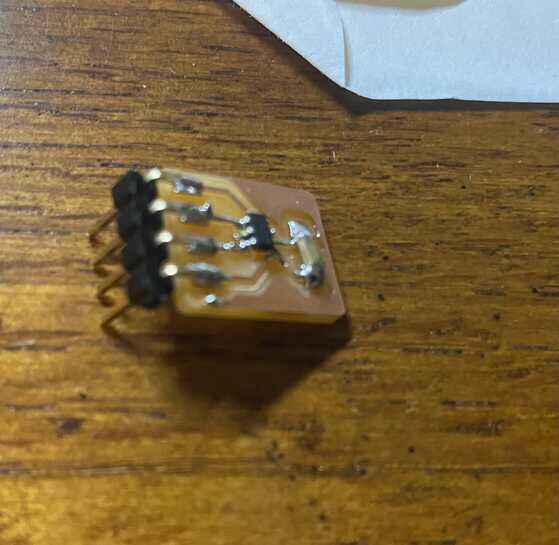
Later I realized that the sensor was placed too far from the edge, so I just moved it over so that it could be closer to the zero position.
Determining zero
I uploaded the following code to the main board so that it would send data from the sensor whenever requested, and it would request twice each time to make sure up to date data was sent.
#include <Wire.h>
#define INPUTADR 0x35

void setup() {
  // put your setup code here, to run once:
  Serial.begin(9600);
  Wire.begin();
  PORTB.PIN0CTRL |= 1 << 3;
  PORTB.PIN1CTRL |= 1 << 3;
  Wire.setClock(400000);
   //
   // reset TLE493D
   //
   Wire.beginTransmission(INPUTADR);
   Wire.write(0xFF);
   Wire.endTransmission();
   Wire.beginTransmission(INPUTADR);
   Wire.write(0xFF);
   Wire.endTransmission();
   Wire.beginTransmission(INPUTADR);
   Wire.write(0x00);
   Wire.endTransmission();
   Wire.beginTransmission(INPUTADR);
   Wire.write(0x00);
   Wire.endTransmission();
   delayMicroseconds(50);
   //
   // configure TLE493D
   //
   Wire.beginTransmission(INPUTADR);
   Wire.write(0x10);
   Wire.write(0x28);
      // config register 0x10
      // ADC trigger on read after register 0x05
      // short-range sensitivity
   Wire.write(0x15);
      // mode register 0x11
      // 1-byte read protocol
      // interrupt disabled
      // master controlled mode
   Wire.endTransmission();
}

void loop() {
  // put your main code here, to run repeatedly:
  while(Serial.available()== 0);
  int command = Serial.parseInt();

  if (command == 1) {
    uint8_t data[6];
    int transformedData[3];
    Wire.requestFrom(INPUTADR, 6);
    for (int i = 0; i < 6; ++i) {
      data[i] = Wire.read();
    }
    delayMicroseconds(100);
    Wire.requestFrom(INPUTADR, 6);
    for (int i = 0; i < 6; ++i) {
      data[i] = Wire.read();
    }
    transformedData[0] = (data[0] << 4)+((data[4] & 0xF0) >> 4);
    transformedData[1] = (data[1] << 4)+(data[4] & 0x0F);
    transformedData[2] = (data[2] << 4)+(data[5] & 0x0F);
    for (int i = 0; i < 3; ++i) {
      if (transformedData[i] > 2047) transformedData[i] -= 4096;
      Serial.print(transformedData[i]);
      Serial.print(' ');
    }
    Serial.print('\n');
  }
}
I then wrote the following python code to grab the data through serial via an ftdi chip, process it into angles, and print it to the command line. I used this method of zeroing since while searching for ways to convert magnetic flux to distance values, I came across incredibly inconsistent information with some claiming it to be an inverse squared relation, some inverse cubed, and even once claiming inverse to the fifth power. Since I only had a 2d gantry while having measurements in 3d space, each set of angles would be unique as the z distance is fixed.
import serial
from time import sleep
import math

ser = serial.Serial("COM5", 9600)
ser.setDTR()

while True:
    message = "1"
    ser.write(message.encode("raw_unicode_escape"))
    while ser.in_waiting == 0:
        pass
    sleep(0.01)
    input_message = str(ser.readline())
    input_message = input_message[2:len(input_message) - 4]
    input_vals = input_message.split(' ')
    input_vals = [int(i) for i in input_vals]
    print(input_vals)
    xy_angle = 90
    if (input_vals[0] != 0):
        xy_angle = math.degrees(math.atan(input_vals[1] / input_vals[0]))
    z_angle = 90
    if (math.sqrt(input_vals[0] ** 2 + input_vals[1] ** 2) != 0):
        z_angle = math.degrees(math.atan(input_vals[2] / math.sqrt(input_vals[0] ** 2 + input_vals[1] ** 2)))
    print(xy_angle)
    print(z_angle)
I then moved the gantry to the zero position and recorded the values.
At the end, I also move the gantry a bit away to see how the data would change.
Interface
I made an interface using tkinter as doing the group work using it for interfacing week was nice, and my instructor, Dr. Fagan, recommended it. At first, an interesting thing was happening when I was making the buttons in a list outside of an object while giving each the command to return i and j, thinking that it would store those values in the lambda, but all the buttons were returning 7, 7 which is where i and j end up in the final iteration, so I believe this is because in python everything is an object, which makes i and j update for everything. Here, my classmate, Nicholas Niles, recommended that I make a class and have each button be stored as an instance variable in that class, and that worked nicely with the following code:
from tkinter import *

square_size = 50
board_offset = 50

class Square():
    first = True
    startx = -1
    starty = -1
    def __init__(self, root, xcoord, ycoord, img):
        self.xcoord = xcoord
        self.ycoord = ycoord
        self.square_size = square_size
        self.board_offset = board_offset
        self.button = Button(root, height=square_size, width=square_size, image=img, command=lambda: update(self.xcoord, self.ycoord))
        self.button.place(x=self.board_offset + self.xcoord * square_size, y=(7 - self.ycoord) * self.square_size + self.board_offset)

root = Tk()
root.geometry(str(square_size * 8 + board_offset * 2) + 'x' + str(square_size * 8 + board_offset * 2))

def update(x, y):
    text.config(text=str(x) + ', ' + str(y) + ', ' + str(Square.first))
    Square.first = not Square.first

board_buttons = []
img_black = PhotoImage(file="black.png")
img_white = PhotoImage(file="white.png")
for i in range(8):
    board_buttons.append([])
    for j in range(8):
        if (i + j) % 2 == 1:
            board_buttons[i].append(Square(root, j, i, img_black))
        else:
            board_buttons[i].append(Square(root, j, i, img_white))

text = Label(root, text="-1, -1")
text.pack()

root.mainloop()
The label at the top shows the selected coordinates, and the true or false records whether it was the first square selected in a pair.
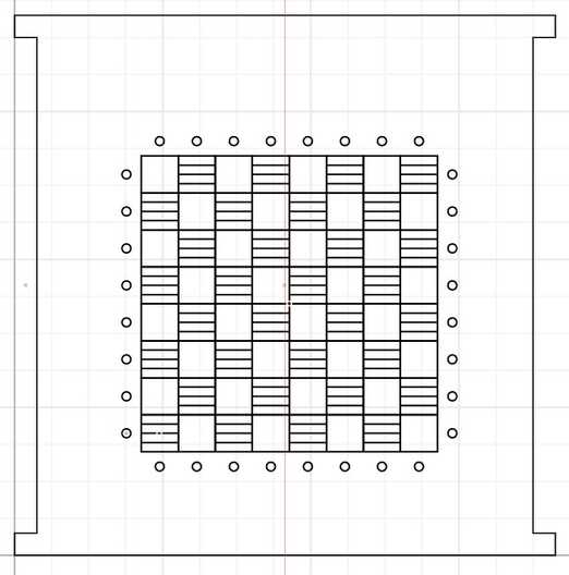
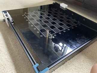
Top board
I designed the top board in cuttle with everything rastered except the outline. I used stripes instead of a filled square for the dark squares because the rastering would create a ridge, and I didn’t want the pieces to get stuck between squares due to the ridge, so stripes would prevent the piece from dropping down into the indented part of the rastering. The circles around the board would be the home positions of the pieces.
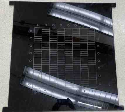
I was running into some bowing issues, so Mr. Budzichowski recommended that I cut strips and attatch them underneath in a square oriented so that the strong width of the strips would resist the bowing.

Walls
These were also designed in cuttle, and the first wall was quite simple being just a rectange with holes for the bolts to go into to secure it to the corners.
I secured it to the corners with bolts and nuts on the other side, and this was done on both corners the wall touched.
For the other wall, I needed holes for the ftdi chip and 5v 5 amp power supply I used, so I added those and did everything else the same as the wall above.

Wire management
I started with just using the arches in the electronics mounts on one of the bases routing wires under them.

This ended up looking like a mess around the main board partially just due to the sheer amount of wires going into it. Another thing that affected this was because the wires were long compared to the distance they had to go, so when they reach the main board, they loop up and result in the mess.
Another way I improved upon this was using ribbon cables, which my teacher, Mr. Durrett, taught me how to make by attaching the header connector on the end of them.
I started with soldering the wire to the connector.
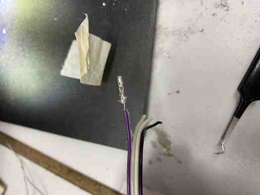
I then crimped the front end with the crimping tool and pushed it into the plastic case.
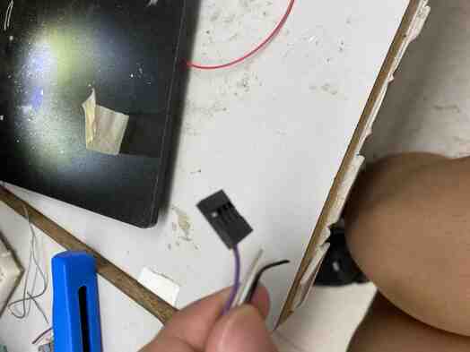
I then repeated this for the rest of the ribbon cable.
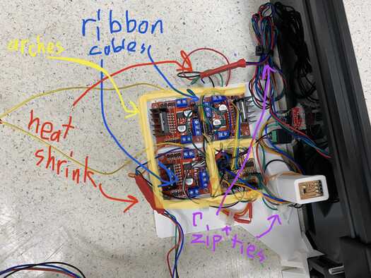
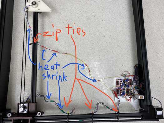
Using ribbon cables for the motor driver inputs and using zip ties both to fasten wires together and to fasten them to the arches and other aspects of the design as well as using heat shrink to keep wires together, I ended up with this organization. Below are both labeled and unlabeled versions of it.

For the organization of the wires on the gantry, Graham Smith advised me to loosely zip tie the wire to the gantry frame and use another zip tie to fasten the wire to the loosely tied zip tie, and that worked nicely.
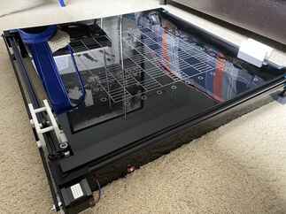
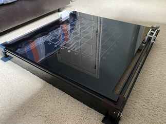
Putting it all together
I now combined all my work above to form the final product. This is split in a few areas of functionality.
Final packaging
The final wire management can be seen above in the final picutures of the wire management section, and with the walls and top board in place, it nicely hides all the wires as well. Below shows the final packaging from each of the 4 corners.

Zeroing
For the zeroing, I used the process described above in my input testing section, but now I got it implemented with the gantry with the following code:
PC main.py (at this stage the interface had not been implemented into this yet)
from command_funcs import *
import serial

class Square():
    ser = serial.Serial("COM5", 9600)
    ser.setDTR()
    first = True
    startx = -1
    starty = -1
    posx = -1
    poxy = -1
    steps_per_square = int(50 / (12 * math.pi / 200))
    steps_home = int(20 / (12 * math.pi / 200))
    steps_sol_rad = int(12.5 / (12 * math.pi / 200))


desiredxy = 15
desiredz = 79.7
tolerance = 1
while True:
    xyangle, zangle, input_vals = request_input(Square.ser)
    if xyangle < 0:
        xyangle *= -1
    if zangle < 0:
        zangle *= -1
    if input_vals[0] > 0:
        send_xsteps(Square.ser, 1)
    elif input_vals[1] > 0:
        send_ysteps(Square.ser, 1)
    elif xyangle < desiredxy - tolerance:
        if zangle < desiredz:
            send_xsteps(Square.ser, -1)
        else:
            send_ysteps(Square.ser, 1)
    elif xyangle > desiredxy + tolerance:
        if zangle < desiredz:
            send_ysteps(Square.ser, -1)
        else:
            send_xsteps(Square.ser, 1)
    elif zangle > desiredz + tolerance:
        send_ysteps(Square.ser, 1)
        send_xsteps(Square.ser, 1)
    elif zangle < desiredz - tolerance:
        send_ysteps(Square.ser, -1)
        send_xsteps(Square.ser, -1)
    else:
        break
send_xsteps(Square.ser, 47 / (12 * math.pi / 200) * (50 / 53))
PC command_funcs.py (this would not be changed in the future)
import math
from time import sleep

def send_xsteps(ser, steps):
    ser.write("3\n".encode("raw_unicode_escape"))
    ser.write(str(steps).encode("raw_unicode_escape"))
    while ser.in_waiting == 0:
        pass
    ser.readline()

def send_ysteps(ser, steps):
    ser.write("1\n".encode("raw_unicode_escape"))
    ser.write(str(steps).encode("raw_unicode_escape"))
    while ser.in_waiting == 0:
        pass
    ser.readline()

def engage_solenoid(ser):
    ser.write("2\n".encode("raw_unicode_escape"))
    while ser.in_waiting == 0:
        pass
    ser.readline()

def disengage_solenoid(ser):
    ser.write("0\n".encode("raw_unicode_escape"))
    while ser.in_waiting == 0:
        pass
    ser.readline()

def request_input(ser):
    ser.write("4\n".encode("raw_unicode_escape"))
    sleep(0.01)
    input_message = str(ser.readline())
    input_message = input_message[2:len(input_message) - 4]
    input_vals = input_message.split(' ')
    input_vals = [int(i) for i in input_vals]
    xy_angle = 90
    if (input_vals[0] != 0):
        xy_angle = math.degrees(math.atan(input_vals[1] / input_vals[0]))
    z_angle = 90
    if (math.sqrt(input_vals[0] ** 2 + input_vals[1] ** 2) != 0):
        z_angle = math.degrees(math.atan(input_vals[2] / math.sqrt(input_vals[0] ** 2 + input_vals[1] ** 2)))
    return xy_angle, z_angle, input_vals
Main microcontroller (this would not be changed in the future)
#include <Wire.h>
#define INPUTADR 0x35
#define YSTEPPER 0x0A
#define XSTEPPER 0x09

void setup() {
  // put your setup code here, to run once:
  Serial.begin(9600);
  Wire.begin();
  PORTB.PIN0CTRL |= 1 << 3;
  PORTB.PIN1CTRL |= 1 << 3;
  Wire.setClock(400000);
   //
   // reset TLE493D
   //
   Wire.beginTransmission(INPUTADR);
   Wire.write(0xFF);
   Wire.endTransmission();
   Wire.beginTransmission(INPUTADR);
   Wire.write(0xFF);
   Wire.endTransmission();
   Wire.beginTransmission(INPUTADR);
   Wire.write(0x00);
   Wire.endTransmission();
   Wire.beginTransmission(INPUTADR);
   Wire.write(0x00);
   Wire.endTransmission();
   delayMicroseconds(50);
   //
   // configure TLE493D
   //
   Wire.beginTransmission(INPUTADR);
   Wire.write(0x10);
   Wire.write(0x28);
      // config register 0x10
      // ADC trigger on read after register 0x05
      // short-range sensitivity
   Wire.write(0x15);
      // mode register 0x11
      // 1-byte read protocol
      // interrupt disabled
      // master controlled mode
   Wire.endTransmission();

   PORTA.DIRSET |= 1 << 4;
   PORTA.DIRSET |= 1 << 5;
   PORTA.OUT &= ~(1 << 4);
   PORTA.OUT &= ~(1 << 5);
}

void loop() {
  // put your main code here, to run repeatedly:
  while (Serial.available() == 0);
  int command = Serial.parseInt();
  if (command == 3) {
    while (Serial.available() == 0);
    int numSteps = Serial.parseInt();
    sendSteps(numSteps * -1, XSTEPPER);
    Serial.println(1);
  } else if (command == 1) {
    while (Serial.available() == 0);
    int numSteps = Serial.parseInt();
    sendSteps(numSteps * -1, YSTEPPER);
    Serial.println(1);
  } else if (command == 2) {
    PORTA.OUT |= 1 << 4;
    delay(10);
    Serial.println(1);
  } else if (command == 0) {
    PORTA.OUT &= ~(1 << 4);
    delay(10);
    Serial.println(1);
  } else if (command == 4) {
    uint8_t data[6];
    int transformedData[3];
    Wire.requestFrom(INPUTADR, 6);
    for (int i = 0; i < 6; ++i) {
      data[i] = Wire.read();
    }
    delayMicroseconds(100);
    Wire.requestFrom(INPUTADR, 6);
    for (int i = 0; i < 6; ++i) {
      data[i] = Wire.read();
    }
    transformedData[0] = (data[0] << 4)+((data[4] & 0xF0) >> 4);
    transformedData[1] = (data[1] << 4)+(data[4] & 0x0F);
    transformedData[2] = (data[2] << 4)+(data[5] & 0x0F);
    delayMicroseconds(100);
    for (int i = 0; i < 3; ++i) {
      if (transformedData[i] > 2047) transformedData[i] -= 4096;
      Serial.print(transformedData[i]);
      Serial.print(' ');
    }
    Serial.print('\n');
  }
}

void sendSteps(const int& steps, const byte address) {
  if (steps < 0) {
    for (int i = 0; i < steps * -1; ++i) {
      Wire.beginTransmission(address);
      int8_t val = -1;
      Wire.write(val);
      Wire.endTransmission();
      delay(10);
    }
  } else {
    for (int i = 0; i < steps; ++i) {
      Wire.beginTransmission(address);
      int8_t val = 1;
      Wire.write(val);
      Wire.endTransmission();
      delay(10);
    }
  }
}
X stepper microcontroller (this would not be changed in the future)
#include <Wire.h>

#define ADDRESS 0x09

class Stepper {
  private:
  int pin1shift, pin2shift, pin3shift, pin4shift;
  volatile byte& reg1;
  volatile byte& reg2;
  volatile byte& reg3;
  volatile byte& reg4;
  int stepPos;
  int delayTime;

  public:
  Stepper(volatile byte& r1, int p1, volatile byte& r2, int p2, volatile byte& r3, int p3, volatile byte& r4, int p4, int del): pin1shift(p1), reg1(r1), pin2shift(p2), reg2(r2), pin3shift(p3), reg3(r3), pin4shift(p4), reg4(r4), delayTime(del) {
    stepPos = 0;
  }

  private:
  void out1() {
    reg1 |= 1 << pin1shift;
  }

  void clear1() {
    reg1 &= ~(1 << pin1shift);
  }

  void out2() {
    reg2 |= 1 << pin2shift;
  }

  void clear2() {
    reg2 &= ~(1 << pin2shift);
  }

  void out3() {
    reg3 |= 1 << pin3shift;
  }

  void clear3() {
    reg3 &= ~(1 << pin3shift);
  }

  void out4() {
    reg4 |= 1 << pin4shift;
  }

  void clear4() {
    reg4 &= ~(1 << pin4shift);
  }

  void runStep() {
    switch (stepPos) {
      case 0:
      out1();
      clear2();
      out3();
      clear4();
      break;
      case 1:
      clear1();
      out2();
      out3();
      clear4();
      break;
      case 2:
      clear1();
      out2();
      clear3();
      out4();
      break;
      case 3:
      out1();
      clear2();
      clear3();
      out4();
      break;
    }
    delay(delayTime);
  }

  public:
  void stepCW(int numSteps) {
    for (int i = 0; i < numSteps; ++i) {
      stepPos = (stepPos + 1) % 4;
      runStep();
    }
  }

  void stepCCW(int numSteps) {
    for (int i = 0; i < numSteps; ++i) {
      --stepPos;
      if (stepPos < 0) stepPos = 3;
      runStep();
    }
  }
};

void setup() {
  // put your setup code here, to run once:
  Wire.begin(ADDRESS);
  PORTA.DIRSET |= 1 << 4;
  PORTA.DIRSET |= 1 << 5;
  PORTA.DIRSET |= 1 << 3;
  PORTB.DIRSET |= 1 << 2;
  Wire.onReceive(doStep);
}

Stepper myStepper(PORTA.OUT, 4, PORTA.OUT, 5, PORTB.OUT, 2, PORTA.OUT, 3, 0);

void loop() {
  // put your main code here, to run repeatedly:
  delay(10);
}

void doStep(int numBytes) {
  int8_t steps = Wire.read();
  if (steps < 0) myStepper.stepCCW(1);
  else myStepper.stepCW(1);
}
Y stepper microcontroller (this would not be changed in the future)
#include <Wire.h>

#define ADDRESS 0x0A

class Stepper {
  private:
  int pin1shift, pin2shift, pin3shift, pin4shift;
  volatile byte& reg1;
  volatile byte& reg2;
  volatile byte& reg3;
  volatile byte& reg4;
  int stepPos;
  int delayTime;

  public:
  Stepper(volatile byte& r1, int p1, volatile byte& r2, int p2, volatile byte& r3, int p3, volatile byte& r4, int p4, int del): pin1shift(p1), reg1(r1), pin2shift(p2), reg2(r2), pin3shift(p3), reg3(r3), pin4shift(p4), reg4(r4), delayTime(del) {
    stepPos = 0;
  }

  private:
  void out1() {
    reg1 |= 1 << pin1shift;
  }

  void clear1() {
    reg1 &= ~(1 << pin1shift);
  }

  void out2() {
    reg2 |= 1 << pin2shift;
  }

  void clear2() {
    reg2 &= ~(1 << pin2shift);
  }

  void out3() {
    reg3 |= 1 << pin3shift;
  }

  void clear3() {
    reg3 &= ~(1 << pin3shift);
  }

  void out4() {
    reg4 |= 1 << pin4shift;
  }

  void clear4() {
    reg4 &= ~(1 << pin4shift);
  }

  void runStep() {
    switch (stepPos) {
      case 0:
      out1();
      clear2();
      out3();
      clear4();
      break;
      case 1:
      clear1();
      out2();
      out3();
      clear4();
      break;
      case 2:
      clear1();
      out2();
      clear3();
      out4();
      break;
      case 3:
      out1();
      clear2();
      clear3();
      out4();
      break;
    }
    delay(delayTime);
  }

  public:
  void stepCW(int numSteps) {
    for (int i = 0; i < numSteps; ++i) {
      stepPos = (stepPos + 1) % 4;
      runStep();
    }
  }

  void stepCCW(int numSteps) {
    for (int i = 0; i < numSteps; ++i) {
      --stepPos;
      if (stepPos < 0) stepPos = 3;
      runStep();
    }
  }
};

void setup() {
  // put your setup code here, to run once:
  Wire.begin(ADDRESS);
  PORTA.DIRSET |= 1 << 4;
  PORTA.DIRSET |= 1 << 5;
  PORTA.DIRSET |= 1 << 3;
  PORTB.DIRSET |= 1 << 2;
  Wire.onReceive(doStep);
}

Stepper myStepper(PORTA.OUT, 4, PORTA.OUT, 5, PORTB.OUT, 2, PORTA.OUT, 3, 0);

void loop() {
  // put your main code here, to run repeatedly:
  delay(10);
}

void doStep(int numBytes) {
  int8_t steps = Wire.read();
  if (steps < 0) myStepper.stepCCW(1);
  else myStepper.stepCW(1);
}
This worked nicely.
Note that this is sped up 4x
Moving 1 piece
I edited the main.py code to be the following code:
from tkinter import *
import serial
from time import sleep
from command_funcs import *
import math


square_size = 50
board_offset = 50

class Square():
    ser = serial.Serial("COM5", 9600)
    ser.setDTR()
    first = True
    startx = -1
    starty = -1
    posx = -1
    posy = -1
    steps_per_square = int(50 / (12 * math.pi / 200) * (50 / 53))
    steps_home = int(20 / (12 * math.pi / 200) * (50 / 53))
    steps_sol_rad = int(12.5 / (12 * math.pi / 200) * (50 / 53))
    def __init__(self, root, xcoord, ycoord, img):
        self.xcoord = xcoord
        self.ycoord = ycoord
        self.square_size = square_size
        self.board_offset = board_offset
        self.button = Button(root, height=square_size, width=square_size, image=img, command=lambda: update(self.xcoord, self.ycoord))
        self.button.place(x=self.board_offset + self.xcoord * square_size, y=(7 - self.ycoord) * self.square_size + self.board_offset)

root = Tk()
root.geometry(str(square_size * 8 + board_offset * 2) + 'x' + str(square_size * 8 + board_offset * 2))

def update(x, y):
    text.config(text=str(x) + ', ' + str(y) + ', ' + str(Square.first))
    if Square.first:
        Square.startx = x
        Square.starty = y
    else:
        disengage_solenoid(Square.ser)
        if Square.posx == -1:
            send_xsteps(Square.ser, Square.steps_home)
            send_xsteps(Square.ser, int(Square.steps_per_square / 2))
            Square.posx = 0
        elif Square.posx == 8:
            send_xsteps(Square.ser, Square.steps_home * -1)
            send_xsteps(Square.ser, int(Square.steps_per_square / -2))
            Square.posx = 7
        if Square.posy == -1:
            send_ysteps(Square.ser, Square.steps_home)
            send_ysteps(Square.ser, int(Square.steps_per_square  / 2))
            Square.posy = 0
        elif Square.posy == 8:
            send_ysteps(Square.ser, Square.steps_home * -1)
            send_ysteps(Square.ser, int(Square.steps_per_square / -2))
            Square.posy = 7
        send_xsteps(Square.ser, (Square.posx - Square.startx) * Square.steps_per_square)
        send_ysteps(Square.ser, (Square.posy - Square.starty) * Square.steps_per_square)
        Square.posx = Square.startx
        Square.posy = Square.starty
        engage_solenoid(Square.ser)
        if x - Square.posx == 0:
            send_ysteps(Square.ser, (y - Square.posy) * Square.steps_per_square)
            if y - Square.posy > 0:
                send_ysteps(Square.ser, Square.steps_sol_rad)
                send_ysteps(Square.ser, Square.steps_sol_rad * -1)
            elif y - Square.posy < 0:
                send_ysteps(Square.ser, Square.steps_sol_rad * -1)
                send_ysteps(Square.ser, Square.steps_sol_rad)
        elif y - Square.posy == 0:
            send_xsteps(Square.ser, (x - Square.posx) * Square.steps_per_square)
            if x - Square.posx > 0:
                send_xsteps(Square.ser, Square.steps_sol_rad)
                send_xsteps(Square.ser, Square.steps_sol_rad * -1)
            elif x - Square.posx < 0:
                send_xsteps(Square.ser, Square.steps_sol_rad * -1)
                send_xsteps(Square.ser, Square.steps_sol_rad)
        elif x - Square.posx == y - Square.posy:
            if x - Square.posx > 0:
                for i in range((x - Square.posx) * Square.steps_per_square + int(Square.steps_sol_rad / math.sqrt(2))):
                    send_xsteps(Square.ser, 1)
                    send_ysteps(Square.ser, 1)
            else:
                for i in range((x - Square.posx) * Square.steps_per_square * -1 + int(Square.steps_sol_rad / math.sqrt(2))):
                    send_xsteps(Square.ser, -1)
                    send_ysteps(Square.ser, -1)
        elif x - Square.posx == -1 * (y - Square.posy):
            if x - Square.posx > 0:
                for i in range((x - Square.posx) * Square.steps_per_square + int(Square.steps_sol_rad / math.sqrt(2))):
                    send_xsteps(Square.ser, 1)
                    send_ysteps(Square.ser, -1)
            else:
                for i in range((y - Square.posy) * Square.steps_per_per + int(Square.steps_sol_rad / math.sqrt(2))):
                    send_xsteps(Square.ser, -1)
                    send_ysteps(Square.ser, 1)
        else:
            disengage_solenoid(Square.ser)
            return
        Square.posx = x
        Square.posy = y
        disengage_solenoid(Square.ser)

    Square.first = not Square.first

def zero():
    desiredxy = 15
    desiredz = 79.7
    tolerance = 1
    while True:
        xyangle, zangle, input_vals = request_input(Square.ser)
        if xyangle < 0:
            xyangle *= -1
        if zangle < 0:
            zangle *= -1
        if input_vals[0] > 0:
            send_xsteps(Square.ser, 1)
        elif input_vals[1] > 0:
            send_ysteps(Square.ser, 1)
        elif xyangle < desiredxy - tolerance:
            if zangle < desiredz:
                send_xsteps(Square.ser, -1)
            else:
                send_ysteps(Square.ser, 1)
        elif xyangle > desiredxy + tolerance:
            if zangle < desiredz:
                send_ysteps(Square.ser, -1)
            else:
                send_xsteps(Square.ser, 1)
        elif zangle > desiredz + tolerance:
            send_ysteps(Square.ser, 1)
            send_xsteps(Square.ser, 1)
        elif zangle < desiredz - tolerance:
            send_ysteps(Square.ser, -1)
            send_xsteps(Square.ser, -1)
        else:
            break
    send_xsteps(Square.ser, 47 / (12 * math.pi / 200) * (50 / 53))

def begin():
    zero()
    home1 = [True, True, True, False, False, False, False, False]
    home2 = [False, False, False, False, False, False, False, False]
    home3 = [False, False, False, False, False, False, False, False]
    home4 = [False, False, False, False, False, False, False, False]

    for home in range(len(home1)):
        if home1[home]:
            disengage_solenoid(Square.ser)
            if Square.posy == 8:
                send_ysteps(Square.ser, Square.steps_home * -1)
                Square.posy = 7
            if Square.posx == -1:
                send_xsteps(Square.ser, Square.steps_home + int(Square.steps_per_square / 2))
                Square.posx = 0
            elif Square.posx == 8:
                send_xsteps(Square.ser, Square.steps_home * -1)
                Square.posx = 7
            if Square.posy != -1:
                send_ysteps(Square.ser, Square.steps_per_square * -1 * Square.posy)
                send_ysteps(Square.ser, Square.steps_home * -1)
                Square.posy = -1
            send_xsteps(Square.ser, (home - Square.posx) * Square.steps_per_square)
            Square.posx = home
            engage_solenoid(Square.ser)
            send_ysteps(Square.ser, Square.steps_home)
            send_ysteps(Square.ser, int(Square.steps_per_square * 1.5))
            send_ysteps(Square.ser, Square.steps_sol_rad)
            send_ysteps(Square.ser, Square.steps_sol_rad * -1)
            Square.posy = 1
            disengage_solenoid(Square.ser)

begin()
board_buttons = []
img_black = PhotoImage(file="black.png")
img_white = PhotoImage(file="white.png")
for i in range(8):
    board_buttons.append([])
    for j in range(8):
        if (i + j) % 2 == 1:
            board_buttons[i].append(Square(root, j, i, img_black))
        else:
            board_buttons[i].append(Square(root, j, i, img_white))

text = Label(root, text="-1, -1")
text.pack()

root.mainloop()
This worked nicely for a single piece.
Moving mulitple pieces
During my presentation, Dr. Gershenfeld asked me to get multiple pieces moving, so I tried to do so with the above code, but I ran into some errors.
The first thing I found was that for moving the electromagnet under the piece to be moved, I had the (Square.posx - Square.startx) * Square.steps_per_square instead of (Square.startx - Square.posx) * Square.steps_per_square, so I changed that.
Another problem I was having was that when it would move to the piece to be moved, for some reason, it would move infinitely in the direction of the piece. The weird thing was that it would also move forward in the code to giving the next command and get stuck in the waiting for that command.
My first theory was that the buffer was not being cleared somehow, so I tried clearing it with ser.flush() at the start of each command, but that didn’t work.
I then thought that I needed a small delay between the commands, but that also didn’t work.
I also tried passing Square.ser as a local variable argument ser in case functions linked to tkinter buttons through lambdas were gimmicky with non local variables, but that also didn’t work.
The weird thing that ended up working was adding send_xsteps(ser, 0) before each section except send_ysteps(ser, 0) for the moving the y axis to the right spot to start.
The following code was my final that ended up working:
from tkinter import *
import serial
from time import sleep
from command_funcs import *
import math


square_size = 50
board_offset = 50

class Square():
    ser = serial.Serial("COM5", 9600)
    ser.setDTR()
    first = True
    startx = -1
    starty = -1
    posx = -1
    posy = -1
    steps_per_square = int(50 / (12 * math.pi / 200) * (50 / 53))
    steps_home = int(20 / (12 * math.pi / 200) * (50 / 53))
    steps_sol_rad = int(12.5 / (12 * math.pi / 200) * (50 / 53))
    def __init__(self, root, xcoord, ycoord, img):
        self.xcoord = xcoord
        self.ycoord = ycoord
        self.square_size = square_size
        self.board_offset = board_offset
        self.button = Button(root, height=square_size, width=square_size, image=img, command=lambda: update(self.xcoord, self.ycoord, Square.ser))
        self.button.place(x=self.board_offset + self.xcoord * square_size, y=(7 - self.ycoord) * self.square_size + self.board_offset)

root = Tk()
root.geometry(str(square_size * 8 + board_offset * 2) + 'x' + str(square_size * 8 + board_offset * 2))

def update(x, y, ser):
    text.config(text=str(x) + ', ' + str(y) + ', ' + str(Square.first))
    if Square.first:
        Square.startx = x
        Square.starty = y
    else:
        disengage_solenoid(ser)
        if Square.posx == -1:
            send_xsteps(ser, Square.steps_home)
            send_xsteps(ser, int(Square.steps_per_square / 2))
            Square.posx = 0
        elif Square.posx == 8:
            send_xsteps(ser, Square.steps_home * -1)
            send_xsteps(ser, int(Square.steps_per_square / -2))
            Square.posx = 7
        if Square.posy == -1:
            send_ysteps(ser, Square.steps_home)
            send_ysteps(ser, int(Square.steps_per_square  / 2))
            Square.posy = 0
        elif Square.posy == 8:
            send_ysteps(ser, Square.steps_home * -1)
            send_ysteps(ser, int(Square.steps_per_square / -2))
            Square.posy = 7
        if (Square.startx - Square.posx) * Square.steps_per_square != 0:
            send_xsteps(ser, 0)
            send_xsteps(ser, (Square.startx - Square.posx) * Square.steps_per_square)
        send_xsteps(ser, 0)
        send_ysteps(ser, -250)
        if (Square.starty - Square.posy) * Square.steps_per_square != 0:
            send_ysteps(ser, 0)
            print("in")
            send_ysteps(ser, (Square.starty - Square.posy) * Square.steps_per_square)
        Square.posx = Square.startx
        Square.posy = Square.starty
        send_xsteps(ser, 0)
        engage_solenoid(ser)
        if x - Square.posx == 0:
            send_ysteps(ser, (y - Square.posy) * Square.steps_per_square)
            if y - Square.posy > 0:
                send_ysteps(ser, Square.steps_sol_rad)
                send_ysteps(ser, Square.steps_sol_rad * -1)
            elif y - Square.posy < 0:
                send_ysteps(ser, Square.steps_sol_rad * -1)
                send_ysteps(ser, Square.steps_sol_rad)
        elif y - Square.posy == 0:
            send_xsteps(ser, (x - Square.posx) * Square.steps_per_square)
            if x - Square.posx > 0:
                send_xsteps(ser, Square.steps_sol_rad)
                send_xsteps(ser, Square.steps_sol_rad * -1)
            elif x - Square.posx < 0:
                send_xsteps(ser, Square.steps_sol_rad * -1)
                send_xsteps(ser, Square.steps_sol_rad)
        elif x - Square.posx == y - Square.posy:
            if x - Square.posx > 0:
                for i in range((x - Square.posx) * Square.steps_per_square + int(Square.steps_sol_rad / math.sqrt(2))):
                    send_xsteps(ser, 1)
                    send_ysteps(ser, 1)
            else:
                for i in range((x - Square.posx) * Square.steps_per_square * -1 + int(Square.steps_sol_rad / math.sqrt(2))):
                    send_xsteps(ser, -1)
                    send_ysteps(ser, -1)
        elif x - Square.posx == -1 * (y - Square.posy):
            if x - Square.posx > 0:
                for i in range((x - Square.posx) * Square.steps_per_square + int(Square.steps_sol_rad / math.sqrt(2))):
                    send_xsteps(ser, 1)
                    send_ysteps(ser, -1)
            else:
                for i in range((y - Square.posy) * Square.steps_per_per + int(Square.steps_sol_rad / math.sqrt(2))):
                    send_xsteps(ser, -1)
                    send_ysteps(ser, 1)
        else:
            disengage_solenoid(ser)
            return
        Square.posx = x
        Square.posy = y
        disengage_solenoid(ser)

    Square.first = not Square.first

def zero():
    desiredxy = 15
    desiredz = 79.7
    tolerance = 1
    while True:
        xyangle, zangle, input_vals = request_input(Square.ser)
        if xyangle < 0:
            xyangle *= -1
        if zangle < 0:
            zangle *= -1
        if input_vals[0] > 0:
            send_xsteps(Square.ser, 1)
        elif input_vals[1] > 0:
            send_ysteps(Square.ser, 1)
        elif xyangle < desiredxy - tolerance:
            if zangle < desiredz:
                send_xsteps(Square.ser, -1)
            else:
                send_ysteps(Square.ser, 1)
        elif xyangle > desiredxy + tolerance:
            if zangle < desiredz:
                send_ysteps(Square.ser, -1)
            else:
                send_xsteps(Square.ser, 1)
        elif zangle > desiredz + tolerance:
            send_ysteps(Square.ser, 1)
            send_xsteps(Square.ser, 1)
        elif zangle < desiredz - tolerance:
            send_ysteps(Square.ser, -1)
            send_xsteps(Square.ser, -1)
        else:
            break
    send_xsteps(Square.ser, 47 / (12 * math.pi / 200) * (50 / 53))

def begin():
    zero()
    home1 = [True, True, False, False, False, False, False, False]
    home2 = [False, False, False, False, False, False, False, False]
    home3 = [False, False, False, False, False, False, False, False]
    home4 = [False, False, False, False, False, False, False, False]

    for home in range(len(home1)):
        if home1[home]:
            disengage_solenoid(Square.ser)
            if Square.posy == 8:
                send_ysteps(Square.ser, Square.steps_home * -1 - int(Square.steps_per_square / 2))
                Square.posy = 7
            if Square.posx == -1:
                send_xsteps(Square.ser, Square.steps_home + int(Square.steps_per_square / 2))
                Square.posx = 0
            elif Square.posx == 8:
                send_xsteps(Square.ser, int(Square.steps_home * -1 - Square.steps_per_square / 2))
                Square.posx = 7
            if Square.posy != -1:
                send_ysteps(Square.ser, int(Square.steps_per_square * -1 * Square.posy - Square.steps_per_square / 2))
                send_ysteps(Square.ser, Square.steps_home * -1)
                Square.posy = -1
            send_xsteps(Square.ser, (home - Square.posx) * Square.steps_per_square)
            Square.posx = home
            engage_solenoid(Square.ser)
            send_ysteps(Square.ser, Square.steps_home)
            send_ysteps(Square.ser, int(Square.steps_per_square * 1.5))
            send_ysteps(Square.ser, Square.steps_sol_rad)
            send_ysteps(Square.ser, Square.steps_sol_rad * -1)
            Square.posy = 1
            disengage_solenoid(Square.ser)

begin()
board_buttons = []
img_black = PhotoImage(file="black.png")
img_white = PhotoImage(file="white.png")
for i in range(8):
    board_buttons.append([])
    for j in range(8):
        if (i + j) % 2 == 1:
            board_buttons[i].append(Square(root, j, i, img_black))
        else:
            board_buttons[i].append(Square(root, j, i, img_white))

text = Label(root, text="-1, -1")
text.pack()

root.mainloop()
Possible Future Improvements
To fully flesh out this project, there are a few things that could be done better and added on.
- Creating a final version of the code that can fully check for legal moves
- Changing the zeroing mechanism to something more standard like proximity switches
- Using surface mount motor drivers on the PCB to minimize wires and keep the electronics more compact
- Using a 2 stepper motor mechanism for the x axis to prevent binding while not taking up extra space with the extra roller wings
- Implementing an AI option
Questions from applications and implications
What will it do
For my final project, I wanted to challenge myself with mechanical aspects, and its main purpose is to have a chess board that moves the pieces automatically with an electromagnet underneath. It will also involve an interface with a chess display with which users can input moves, and before sending this to the main system, it will check if it is a legal move.
Who’s done what beforehand
Greg06 on instructables has made a board that does automatic moves, but there are some differences with what I seek to make. Firstly, I will have an interface implemented along with user inputted moves while Greg06’s board has the user manually make the move and a bot respond to it. This means that my board will better be able to make sure all moves made are legal before the pieces are moved along with the fact that there wouldn’t be risk of misalignment of the piece after moving that would cause the magnet to then be unable to move it. Some design process differences are that I will be making my own pieces and I will use microcontrollers and pcb boards instead of an arduino nano.
What will you design
- 2d gantry system
- Chess board top
- Chess pieces
- Networked pcb boards for each stepper motor, the 3d hall effect sensor, and the electromagnet
- Interface displaying virtual board and inputing moves
Materials and components
| Part and link | Source | Quantity | Cost |
|---|---|---|---|
| Electromagnet | Digikey | 1 | 9.95 |
| V slot aluminium extrusions | Amazon | 1 order | 59.99 |
| V slot rollers | Amazon | 9 | 18.98 |
| m4x25 bolts | Amazon | 19 | 4.62 |
| m4 nuts | Amazon | 19 | 5.99 |
| Gear belt | Amazon | 1 | 15.99 |
| Stepper motors | zyltech | 2 | 20.90 |
| L298N motor drivers | Amazon | 3 | 20.97 |
| Magnets | Amazon | 40 | 9.99 |
| Attiny1614 | Digikey | 3 | 3.03 |
| 3d hall effect sensor | Digikey | 1 | 3.05 |
| Black ACM | Piedmont Plastics | 1 | 37.43 |
| total | N/a | N/a | 210.89 |
What parts and systems will be made
The main physical system will be the board with all the electronics controling piece movement. This would include the frame as well as the 2d gantry, top board, and pieces. The main software system will be the interface, which will also check for legal moves, checkmate, and stalemate. This will handle much of the processing power since a PC can execute these data processing aspects quicker, and it eliminates the risk of running out of memory on a microcontroller. These 2 systems will be connected through serial communication.
What processes will be used
- Pcb design for the boards
- Embedded programming
- Interfacing
- Computer controlled cutting for the top board
- 3d printing for most of the gantry besides the aluminium extrusions
- Networking to connect the boards together
What questions need to be answered
I will need to determine the best way to calculate legal moves as well as determining checkmate and stalemate, which, in the best case senario, will hopefully not involve brute forcing all possible moves and checking if they are legal due to losing the king. I will also need to carefully design the gantry system so that the electromagnet is as close to the top board as possible but not draggin accross it.
How will it be evaluated
My project will be evaluated based on how well it moves the pieces in response to move inputs from the interface.