7. Electronics design
This week I learned how to use kicad to design my own PCB boards with the schematic editor and the PCB editor to generate gerber files.
All files used can be found here
LED Button Board
I started with making a schematic in kicad referencing boards that my instructors, Mr. Dubick (left) and Dr. Harris (right), provided.

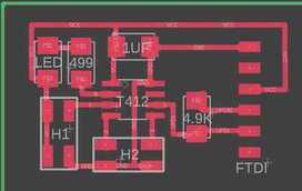
I ended up with the following:
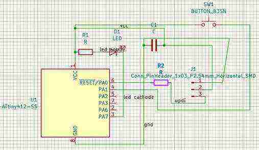
Then, Dr. Harris pointed out to me that I needed to have the button connected to ground to have it be pull up. I also realized that I was using the attiny 412 chip from one of the default libraries rather than the fab one, so I swapped it out. Mr. Dubick told us that to limit errors from the electrical rules checker, we should use the symbol editor to make unused pins labled as disconnected and invisible and add power flags to power and ground since the board expects an external power source.

The only warning from the electrical rules checker was that I edited the attiny 412 symbol, which was intentional and fine.
I then pulled it into the PCB editor and wired everything shown below. Dr. Harris told me to make the traces at least 0.4 thickness, so I made mine 0.6. I also changed the design rules checker to have the minimum trace clearance 0.4.
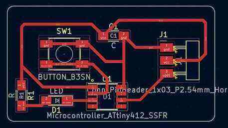
The design rules checker just had some warnings about the silkboard, but our milling machine does not use silkboards, so the board was fine.
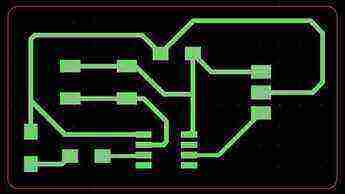
I then got the gerber files by going file > plot, and I unchecked everything except the F.Cu and Edge.Cuts since that is all that needs to be milled. To make sure everything worked well I looked at it in the gerber viewer.
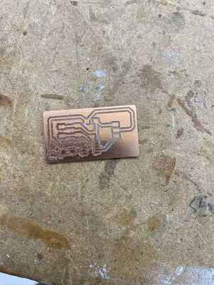
I then milled the board, but the first 2 attempts did not turn out well since part of the trace cut did not go all the way and left some copper.
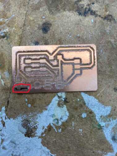
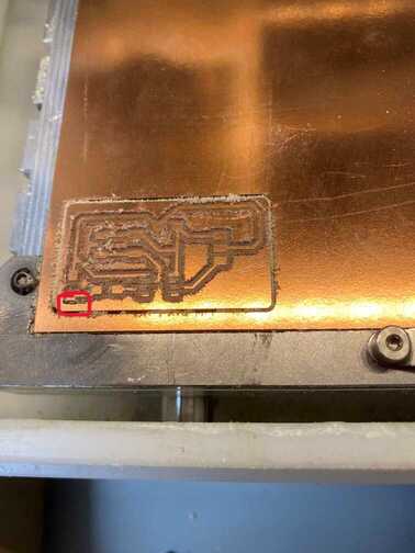
I had thought the first was a fluke due to uneven material thickness, but I realized that I could do a simple fix by increasing the trace depth from 0.15 to 0.25, and that turned out well.
I then soldered the components on.

I then uploaded the following code:
const int ledPin = 1;
const int buttonPin = 0;

void setup() {
  // put your setup code here, to run once:
  pinMode(ledPin, OUTPUT);
  pinMode(buttonPin, INPUT_PULLUP);
}

void loop() {
  // put your main code here, to run repeatedly:
  if (digitalRead(buttonPin) == LOW) {
    digitalWrite(ledPin, LOW);
  } else {
    digitalWrite(ledPin, HIGH);
  }
}
Group Site
Our group work for this week can be found here.
I worked on interpreting the results from the oscilloscope and writing the code for using PWM to observe with the oscilloscope.