Computer Controlled Machining
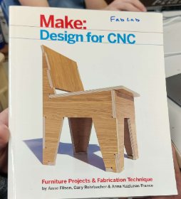
This week’s assignment was to design something that was meter scale and cut it using a CNC machine. I used the book “Make: Design for CNC” that my lab had available. I knew that I already wanted to make a chair so I went through the book to find the best designs. I ultimately decided on creating something similar to what was on the front cover. I have put a picture of the book below. I did want to change my design though from what was on the front page. In the sections below I talk about how it varies.
Designing my Chair
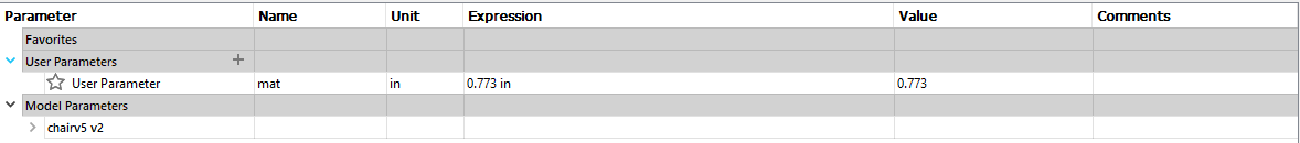
When I was designing my chair, there were a few important things that I needed to keep in mind. The first being the thickness of the stock that I would be using. The best way to incorporate this would be using parametric design that I had learned in the past week. I clicked on the modify parameters tab in Fusion 360 and created a constraint called I referenced a sheet originally that was .773 inches so that is what I used for my parameters. I would later have to adjust this to the material thickness after I determined what thickness I was going to use.
I started by designing the two ends for my chair. At first, I slanted the back of the chair way too much but then I quickly adjusted it. Once I had the rough outline for what my chair would look like, I focused on creating the tabs. While I could have created a parameter for the tab length, I ultimately forgot to and ended up using the equal constraint to make them all the same size. I never ended up changing their size so I never knew if this would have worked. I used the material thickness parameter for the depth of the tab and extended them using the rectangular pattern tool. I also needed to include two holes towards the bottom that would serve as the mounting spots for support. I placed the squares on the same level by using the rectangular pattern tool once again.
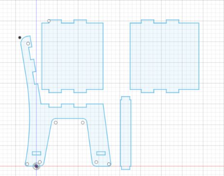
For the plates and braces in between, I started with a set of rectangles. Instead of trying to subtract the tabs from them, I added a set of tabs to each side. This helped me keep everything simple since I learned from Charles De Mey that it is easy to mix them up. I used the same parameter for material thickness so that I could easily adjust the tabs if need be. Once I had added the tabs to everything, I checked that it would all align. First I extruded the piece to the material thickness. After that, I used the move tool to position each part. I also could adjust each object’s opacity so that I could see all parts of the joints.
Testing my design
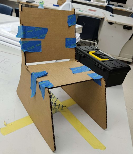
I tested my design using our lab’s laser cutter. This allowed me to scale down my chair and make sure that everything fits together as it had in Fusion 360. Despite the tabs being too long because of the scaling and material thickness differences, everything fit together. For this prototype, I used a previous design. Unfortunately, when I was working on it one night, Fusion 360 crashed and took my chair file as well as some other important files from my bioengineering class. I still have not been able to get those files back. It also helped me because I recognized that I would need to add support in the lower reason. When I tested it by putting weight on it, the legs bowed outwards. but since this was only to test the tabs, I was able to use it. Since it all fit together I moved on to learning Aspire.
Learning Aspire.
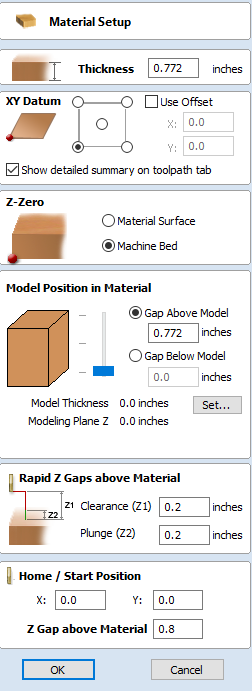 Despite this being the first time that I had used Aspire, I was able to catch on quite quickly. It was very similar to software like Inkscape in the sense that I could easily edit my files. The new part was learning how to use the toolpath features. Before I began, I needed to make sure that I had the material settings correct. The most important thing to set up properly is where to zero the z-axis. The way that my lab does it and our machine is through a Z-plate that detects when the bit hits it and can therefore zero the z. It is also really important to set the proper material thickness. If it is too thin, the material will not be cut through all the way and if it is too much the sacrificial layer will be cut through.
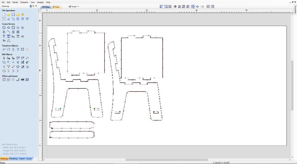
After I made sure to select 0 from the bed and had the proper thickness, I went on to move my file into the software. At first, I tried to import the DXF that I had got from fusion until I realized that it would work. From this point, I could use either an online convertor or Corel Draw to get my file to an SVG. I chose to use an online converter because I did not have Corel Draw on my laptop. Once I had my SVG created, I imported it into Aspire. Originally the file was not scaled properly so it took me a few attempts but I got it. Then I needed to make sure that all the shapes were closed. Originally I tried to select them all at once and use the join vector tool but when this didn’t work, I had to select each line at a time and join them. I faced a lot of issues when creating my dogbone joints. I needed to create them so that my piece would fit together perfectly. The corners originally had 2-4 different nodes within a very small area so I had to delete them. Once the nodes were deleted, I was able to use the dogbone fillet tool to get all my joints perfect.
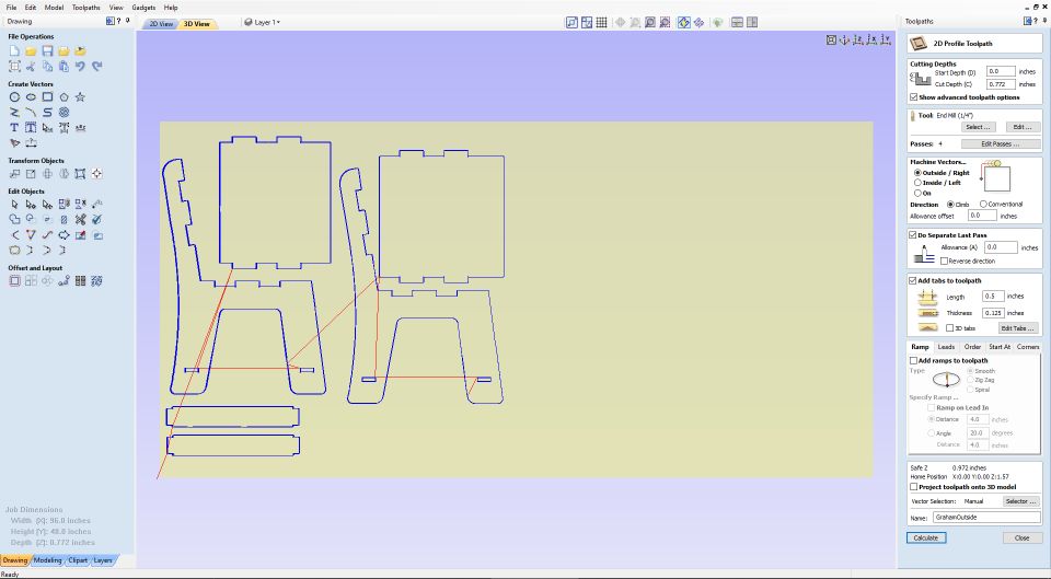
I then needed to create my toolpaths. Since I had never used this Aspire before, I decided for some reason not to look up a tutorial but rather play around until I figured it out. This would lead to a fatal error that I would later have to fix. I did end up learning how to do the tool paths and I thought that it was easier than using the Fusion CAM tool. I started by creating the exterior contours in a profile I called ‘Outside Graham’ It only took a few clicks and I had my outside done. It was while working on the inside my inexperience in the software shown. I used the same techniques for the inside but I did not change from where the bit would cut. Instead of telling the machine to cut from the inside, I left it set to the outside. This threw my tabs off and led me to redo my cut. Luckily I noticed this early on and didn’t end up wasting extra material. After all of this though, there was still one issue looming.
Aspire Demo Version Issue
Since I was doing everything on my laptop, I decided to use the demo version of Aspire because I didn’t have the full version. After two hours of setting up tool paths and troubleshooting, I went to export my file. It allowed me to save it as an Aspire file which I then moved onto the main shopbot computer. When I tried to open it up, I was greeted with a message that said I wasn’t allowed to open this file because it was created in the demo environment. I tried to work around this but ultimately found there was nothing I could do. The next thing that I tried before giving up was to export just the tool path. This didn’t end up working either so I was stuck with a useless file. From this point on, I moved to a different computer within my lab that had the full version of Aspire. On those computers, I tested to make sure I could export before I tried to do the toolpaths again
Using the ShopBot & Safety
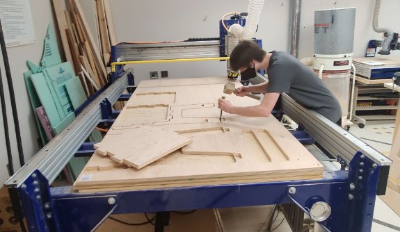
Throughout the week, My instructor constantly reminded my piers and me of the yale student who was killed when working with these dangerous machines. The most important rule that we had while working with this machine was having two people in the room. On top of all the goggles and headphones that we were wearing, having someone with you to go over the workflow was critical. Another very important rule this week was ALWAYS having the workflow open when you are in the room. this made sure that we were focused and always knew the step we had just done, are doing, and need to do in the future. Because of all these rules, no one was injured in our lab this week. Here is a copy of our shop’s workflow: Alpha ShopBot Workflow. Using the shopbot at first seemed intimidating although I had used it the previous year. I won’t go into any detail on how to use it because the workflow shows it all but here is a general explanation. The first thing to do before putting on your piece of stock is to zero the bit against the bed. Then you want to screw on the stock. I chose to use 10 screws, five on each side. Loading Aspire and the shopbot software, you will want to double-check everything before running the air cut. The aircut is critical to do, especially if you have any doubts about where you nested your pieces. If the aircut is successful, the next step is to let everyone know that you are preparing to start your actual cut. Then you can follow that up by running it.
Postproccessing
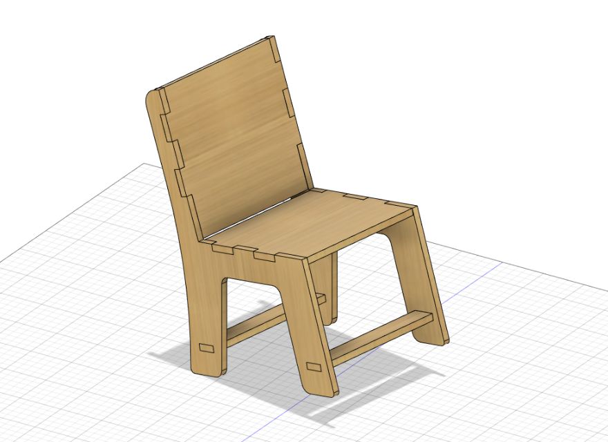
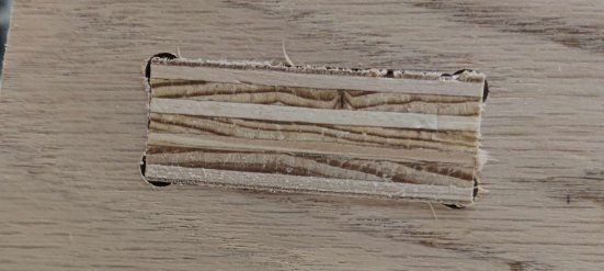
 This is the most important step any time you are working with wood. The first thing I did was use a chisel to remove the material from the rest of the stock. I didn’t use too many tabs (about 6 per piece) so this step did not take long. After that, I used the belt sander to quickly rid the pieces of the remaining tabs. I may have messed up with the next step but I was so eager to see if mine fit together that I assembled it first before really working on sanding. Once I knew it fit together, I then went on and started using finer grit sandpaper to smooth everything out. In the end, I thought my chair turned out good. I have considered staining it on my own time but for now, I will leave it as its natural color
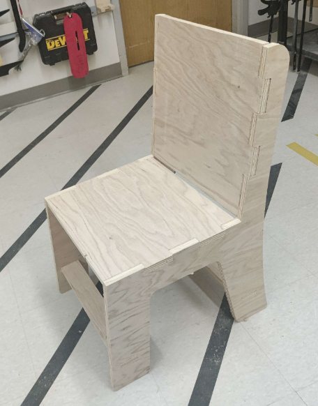
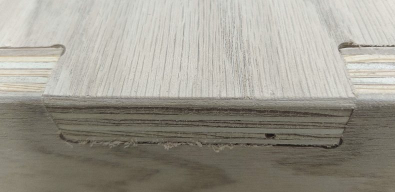
I also noticed that my joints were very tight. I did like this as the goal was not to use any screws or nails to hold it together. I contribute this to my use of parameters. Because I knew the exact thickness I could adjust my design to have minimal clearance within the tabs and therefore they would snap together quite well. I also did not have to do any sanding to the tabs to get them to fit together.
Challenges
The main challenges that I encountered were working through the dogbones. I kept trying over and over again to get each of the corners to be dogbone because I needed them for the joints to fit together. Because of the way that Fusion360 exports files, the lines weren’t lining up to allow for a smooth fillet. I tried to take the simple route of getting around the dogbone joint issue but after a while, I realized that I was going to need to Corel draw to make serious modifications. I ended up resolving this issue by redoing a majority of the lines in Corel draw before exporting it to Aspire. This ended up costing me hours but in the end, allowed my project to work first try.
Group Work
During this week’s group work, I helped run the test for the CNC. The most important part of this week was safety, however. We spent a lot of time talking through what to do if something went from and our instructor did a great job letting us know that it is OK to hit the big red stop button. I was not here to witness or help out with the runout test since I had an appointment. Instead, I worked on the group site when I got back.