Machine Week
Charles, Grant, Graham, Teddy
Because of the number of participants from our lab this year, we decided that the best thing to do was split up the groups. Our instructor suggested that we split up with the people with better coding skills in one group, and the mechanical-minded people in another. The first thing that my group decided to do was go outside and come up with a new idea. Originally as a whole, we decided that we were going to make a motorized etch sketch. We fell in love with this idea because the code would be hard to come up with and the mechanism that would be needed would be hard. I was looking forward to this project since we had been talking about it for the weeks leading up to it but because of the split, we needed to brainstorm something new.
Idea 1
The first idea that we had was a CNC-like machine engraved on a hotdog. We were really into doing something completely useless so this fit right in. during our conversation about this machine, we talked about using a laser to burn a pattern into the hotdog but because of safety concerns we decided that we would do a router. The hardest part that we briefly thought through was making sure that the hotdog was level on the rotating axis. Our first solution was to use a metal rod that would go all the way through. We weren’t able to come up with a way that would make sure it was straight so we started thinking of other things we could do. The next idea was to stretch out the hotdog. By doing this we would know that it would be straight but because of the strain on the hotdog, we thought it may break. Because of many similar issues like this, we decided to move onto idea 2.
Idea 2
Since we had been on the topic of food, we started thinking about preparing food. This is when we had the idea to make a pizza preparing machine. We were inspired by a store in California called [insert name] that uses a large robot to create a burger. Seeing what they had done to one essential part of American cuisine, we knew we needed to replicate this for our pizza machine idea. Once we had our idea, we started to think through our execution. This is when [TEDDY WARNER] had the idea to incorporate tool changing. After thinking through it and consulting our instructor, we started to get an idea of what we wanted our machine to look like. I then went home that same night and designed the entirety of our prototype. I talk more about it in the [designing the prototype] section. Once we had this original design, we went back and consulted our instructor on this design. As he went through it, he used his mechanical engineer background to suggest changes. Out of the entire design, he only suggested a few changes. Teddy and I went back and started to work on the essential changes that he recommended. We weren’t able to present this design to him until after it was too late. Since we had finalized our design, we worked on splitting up the work between the four group members
Splitting it up
When we were splitting it up, we needed to make sure that everyone had a clear understanding of what they were doing. Discord was a great tool that kept us connected because we were out of school for half the time. Teddy was in charge of making sure that the electronics were sorted. Teddy had made his CNC machine a year prior so when it came to creating and editing the firmware, Teddy knew what he was doing. Teddy was also in charge of making the electronics case. He also decided that a working pizza machine was not enough. He added built-in games so that when you are waiting for your pizza to be made, you don’t have to worry about bordem. On top of that, Teddy took the initiative to create the main carriage. With the suggestion of our instructor, he added on z-axis so that we could adjust the tool changing positioning. Charles was in charge of coming up with the actual tool-changing system. He used his unsurpassed skill in Fusion360 to design his parts days ahead of schedule. Originally we were going to use a servo system that could lock in each part but with the guidance of our instructor, we changed to a claw system. Charles with the help of Teddy worked hard to get this system perfect. Grant was in charge of securing the power supply, its components, and the bed. The bed was the most important portion of Grant’s work. He had the great idea to inlay an actual pizza pan so when the pizza is done, it can be directly transferred to the oven. Grant also used living hinges/kerf bending in his design that contained the power supply. He went through a few iterations but eventually found one that worked the best. Grant also volunteered to help compile our group site. My job was to redesign the x/y carriage, design the corners, and also work on any other miscellaneous work that we may encounter. It was when I was working through my x/y carriage design when I had a pure stroke of genius. I realized that instead of relying on the 3d printer to do everything, I could use our lab’s laser cutter to make more than half of it. It saved hours and allowed me to rapidly prototype different designs. When I was working on my corners I needed to make sure that I had enough room for everything to securely fit in. It was also important to have clear communication with Grant as his design depended on mine.
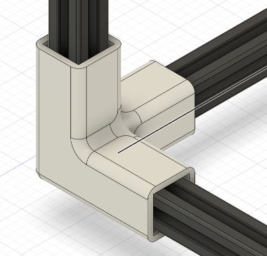
Designing the original corners
When designing the corners there were a few important things to keep in mind. The first being the size of the aluminum extrusion that we were using. We decided to use 20mm extrusion which allowed for a nice balance of size, strength, and durability. In the original design, I tried to use a center rod that allowed the extrusion to be perfectly centered and to lock in. there were a few issues with this, however. The first was the size of the pole. While in concept it should have fit with room to spare, it proved to be useless and even broke off during testing. another issue was the unnecessary print time that it added. Because of its location, I would need to use supports that not only took up extra material but also added an hour of print time. After some conversation with my teammates, we decided to remove it. After removing that and testing, I realized that I needed to add more to the length of each side. Originally only 30mm were contacting the surface. After revision, I upped it to 80mm which had a dramatic effect on the structure of the frame. I made sure to include a chamfer to each opening for easy insertion of the extrusion. My original design also called for the belt tensioners to be a separate piece that would then be screwed into the frame using threaded inserts. I wasn’t taking into account the fact that I could print it in a vertical direction that would eliminate the need for support. I made countless stupid assumptions and errors throughout this project which I will hopefully cover during this
Designing the original main carriage
Designing the original carriage was rather hard. The first thing that I had to do was determine the distance between the rods. We didn’t want to go too wide but at the same time, making them close together was also not optimal. In the end, I decided to make them 90mm apart. I felt this was the best since I ran a few different test parts on our lab’s laser cutter and then seemed to be just far enough apart. After I knew the distance between the two, I needed to research the size of the linear bearings. I found out that the ones we were using had an out diameter of 15mm. I would use 15.07 in my design to provide a little extra room for them to slide in. Now that I knew these numbers I could go back and work on the actual design. I started with a rectangle that was 120 by 120. It was important to have this size or bigger because I knew I needed room for all the tool-changing mechanisms to fit.
Designing the original x-axis system
I based my x-axis on the many designs that I saw online. The core part of it was mounting the stepper motor above the linear rails. I started by making a 2d t shaped design. Included in this design were the proper holes they would hole the stepper motor. I made sure to go back to the datasheet to make sure that I had the right dimension and even went as far as running a quick laser cut to check once more. One I was this design I needed to add a way to make sure the belts were tight. I did this by adding two very small tabs that sat on the outside of the carriage and would attach to two bearings. The next part of my design was working through the way it would attach to the rails. I decided that I would do a set of 4 screws in the base of the system where the screws would be able to go through. I did this and then added a wider hole so that the screws could sit below the stepper.
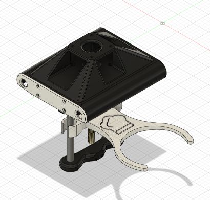
Designing the original tool changing system
For the original tool-changing system, I was going to use a servo to lock in the different components. I first made a rough design of what the carriage could be and worked off of that. I started by making the amount for the servo on one side. I did this by finding the specific servo datasheet. Once I knew the distances between the screws, I extruded two posts that had the proper m2 screw holes. I also designed a little servo that I used to make sure everything would fit. Once I designed that piece, I moved to the opposite side so that I could work on the part that the bar would lock into. I extruded a little cube and then cut a smaller, thinner rectangle into it. I finished it off by using the fillet tool to smooth out all the bodies. Afterward, I went back and added a little screw hole on the left side for an m3 screw. Now that I had the two mechanisms done on the main carriage, I switched over to the working on the bar that would come across. I decided that I would laser cut this so I just made a little 2d sketch. In this sketch, I included a hole for the servo that was the appropriate size. I was also very conscious of the shape. I made sure that it would loop over everything properly and wasn’t interfering with anything. I then needed to edit the receiving end. I only needed to add a slot that would accept the locking mechanism. I did this by creating a rectangle on the top plane and then extruding it down. I needed to make sure that I was leaving enough material for there to be supported while at the same time making sure that the servo would be able to get to that area. I was able to assemble all these parts to make sure they would work together. They all looked like they fit together so I started focusing on designing other parts of our machine
Teacher feedback
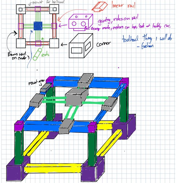
Before we started manufacturing the parts that each of us had made, we met with one of your instructors who is a mechanical engineer. During our talk, he gave us many helpful tips where we could improve our design as well as areas that he liked. The first thing we talked about was general movement. Since my first design, we had already changed over to using v rollers instead of linear rails. We talked to him about this decision where he gave us a helpful tip. he said that it was most efficient to use 3 rollers. I, however, in an act of pure stupidity, decided against this. While it didn’t directly affect our functionality later, It just provided a little extra manufacturing time. After we talked about my x and y carriage design. He suggested a few minor changes that I implemented and will talk about in the next section. We then moved on talking about the tool-changing system. As a reminder, we were planning on using a servo as a locking mechanism with the main carriage facing up, our instructor suggested that we use the z-axis and gravity to hold each piece together. We didn’t know what he meant originally so he made a little drawing to show us what it would look like. We thought this looked good and the concept seems to work. It would also be easier since we could use the marlin that teddy was preparing to control the z-axis. We left Charles with determining how this would work. I would recommend going to Charles’s site to look at what he did since some issues took some time to conquer. With the feedback for those two key components. We talked through everything else and eventually got the go-ahead from our instructor.
Designing the new x/y axis system
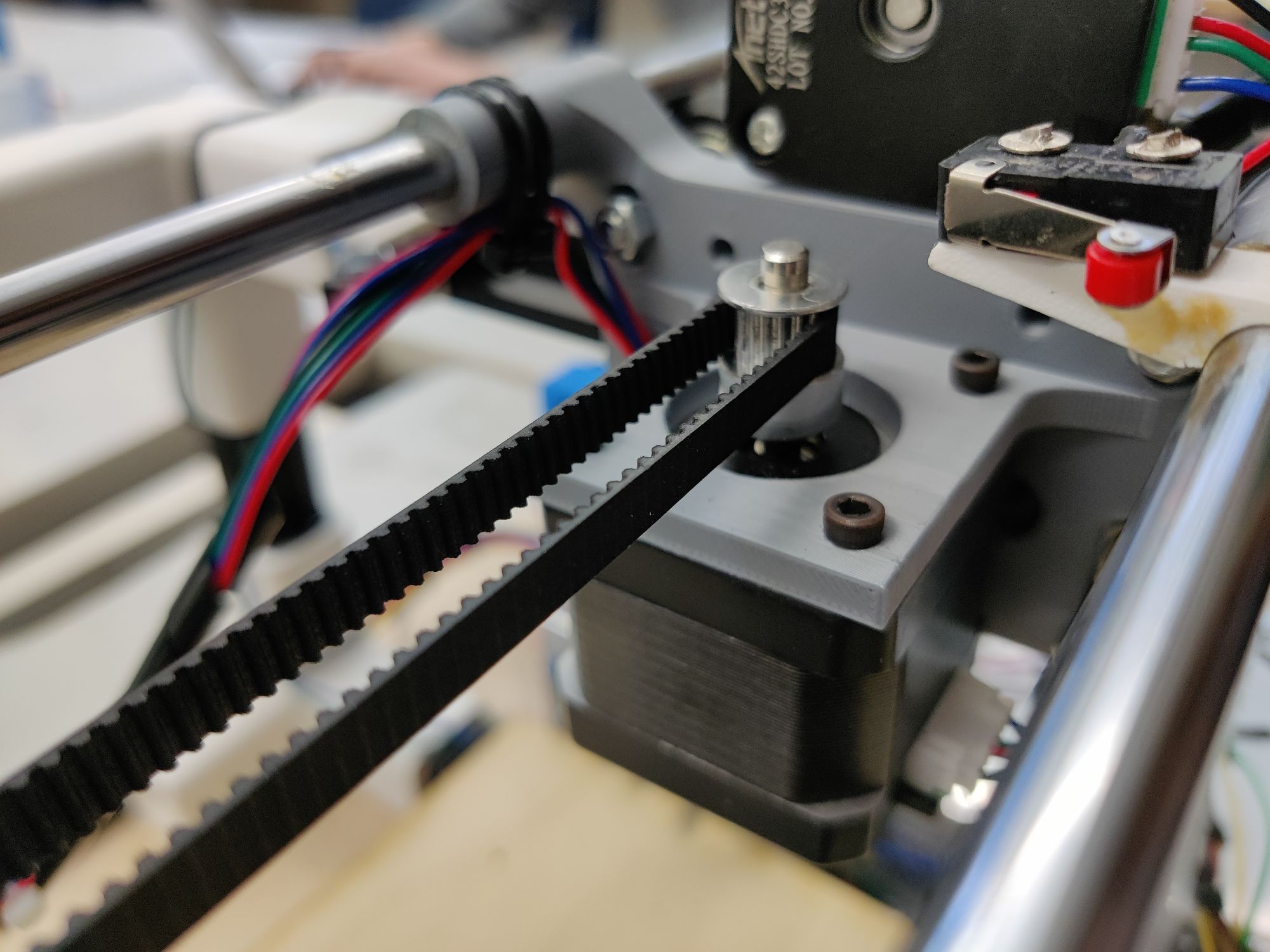
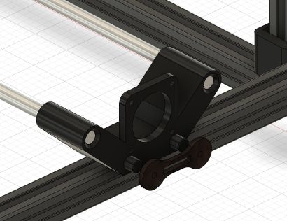
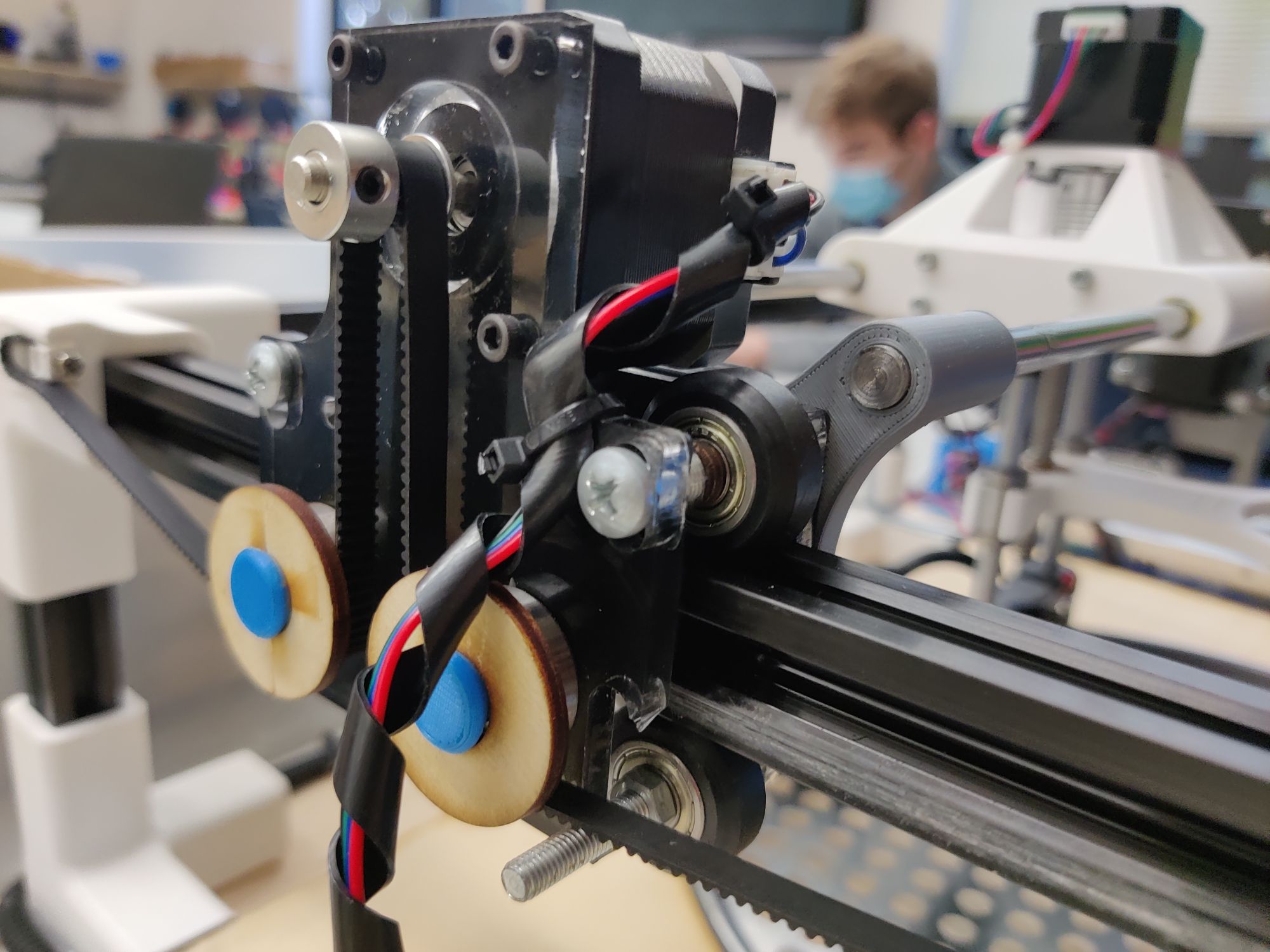
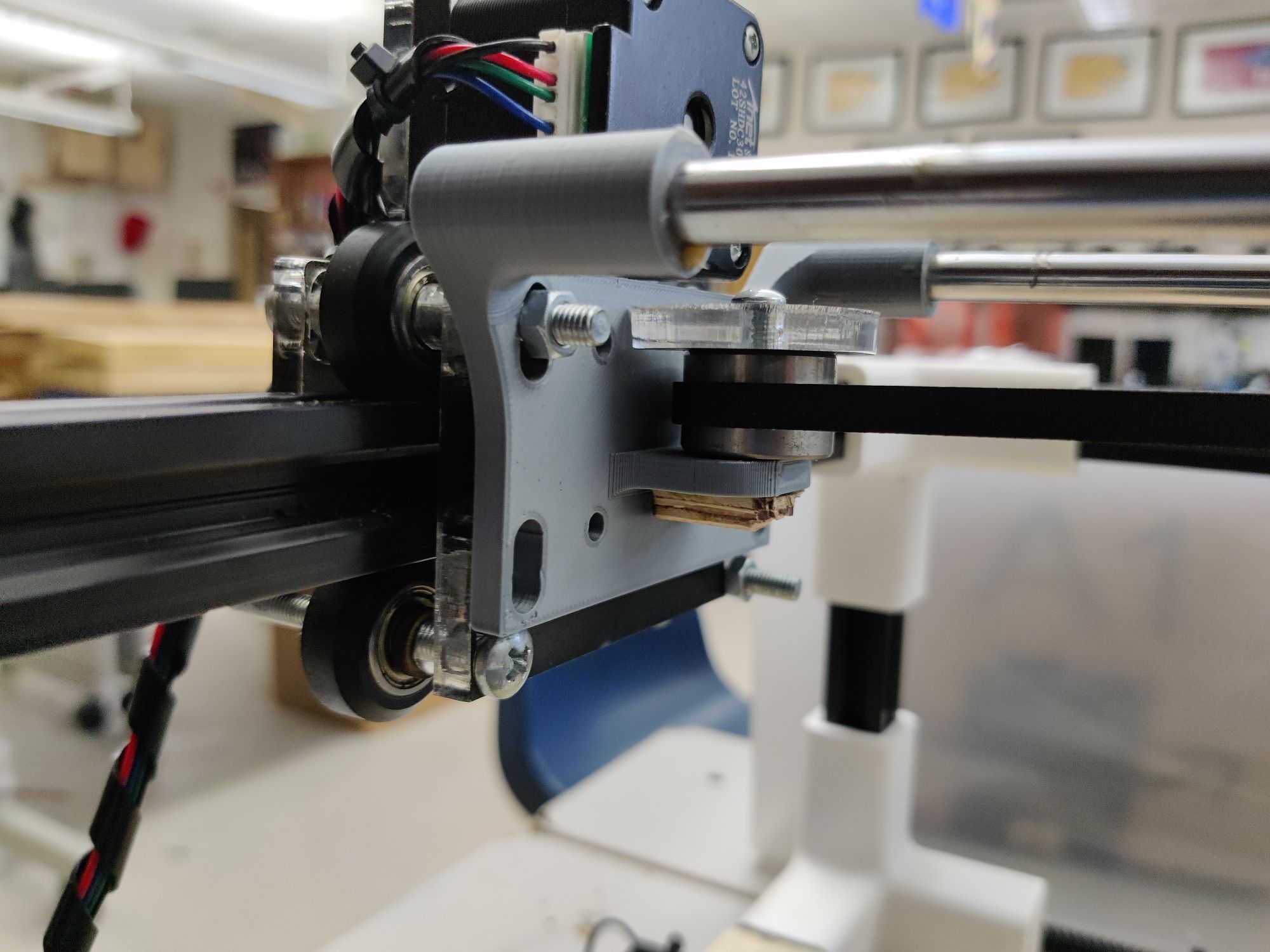
the old system needed a complete redesign. The system that it would be mounted on was different, the size was different, and also the y axis system was different. Originally we were going to put the y axis system on the main carriage but after some talks, we moved it to the same place as the axis system. I decided that I was going to make it all with two parts. One part would be full of mounting holes and be 3d printed and another part that would be laser cut and would hold the x motor. This design proved to be revolutionary as we ended up breaking both sides of the x carriage but because of the reduced production time, they could both be made 50% quicker than before. For the 3d printed part, I needed to include the mount for the two aluminum rods as well as the y axis stepper. On the other side, I would also need to include something for the belt to loop around. The main body started life as a rectangle that was 110 by 90. I then added the same place amount for two steel rods on each side. I also included the holes for the v roller mounts. I made sure that I shaped them like oval so that they could be adjusted. I extruded this basic piece for 20 mm and then the rod holders a little further. For the stepper motor side, I used the same Nema 17 schematics to layout the holes on a 45mm rectangle that I extruded from the rest of the body. For the alternative side, I just made a little l shaped piece that came out. I made the end a cylinder so that I could use it to slide on two bearings. I forgot to add a ‘top’ to this piece so we ended up using a threaded insert to hold on a laser cut circle. This kept the belt on quite well and allowed us to adjust the tension as well. For the 3d, laser-cut piece, I projected the first sketch and then traced the important components over. I then added the top mount for the x-axis stepper motor. I ended up copying over the NEMA 17 diagram that I had made for the motor so I could make sure that everything was consistent. this piece was symmetrical so I didn’t need to create a separate one for the tensioner side. After I made this system, I added it to our main fusion file so that we could see our machine as it was put together.
Troubleshooting the x/y system
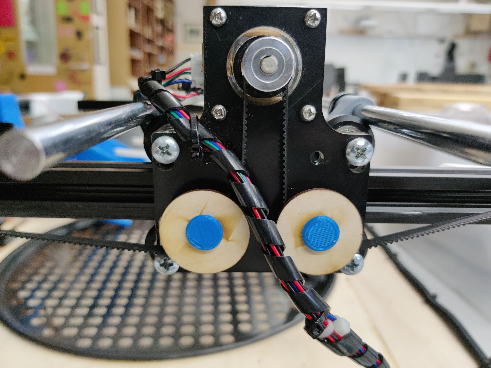
When we started assembling the machine, we encountered numerous issues. The main issue that we faced was in my design. The clearances on the x-axis carriage were way too tight, by something around the lines of 10 mm on each side. I had made the holes for the v rollers to mount on 25mm apart max and with the aluminum extrusion already 20mm, I left no room for the actual wheels to fit on. I should have recognized this when I was testing out the design via my laser cut part. Luckily, however, I did realize this issue before it started to delay the rest of the project. I quickly went back into Fusion and made the mounts 15 mm farther apart on each side. This provided more than enough room for the wheels to slide over the carriage during assembly and also allowed them to be tightened perfectly. This simple mistake ended up helping me create a far better design when it came down to the end so overall my teammates weren’t too frustrated. Another issue that we faced when working on the x-axis was the clearances between the inside of each part and the aluminum extrusion. Instead of going into Fusion and designing a part that could be needed to be printed, I took to the laser cutter to create a simple fix first in cardboard and then in wood. These simple oval spacers weren’t entirely needed because the carriage still rolled perfectly but ended up helping out in the end. The third issue that we faced with the x carriage was the clearance on the rod holders. Since I had made them 8.05mm in Fusion, the fit was rather tight. I fixed this issue once more by using some of the 3d printing lubricants that we had in the lab. Once I applied a generous amount, we were able to use a mallet to lightly tap each piece into place. The final issue that we faced with the carriage was the strength of the parts. On two separate occasions, we broke each side. We ended up at first printing out a new one for the servo side and then for the other side, I printed out an extra piece in anticipation of it breaking, which it did. Once these two pieces broke, I knew that I needed to make major design changes. As I was making some of these changes, we got the machine completely working and no longer needed them. Despite this sounding like all of our issues, this was only the start.
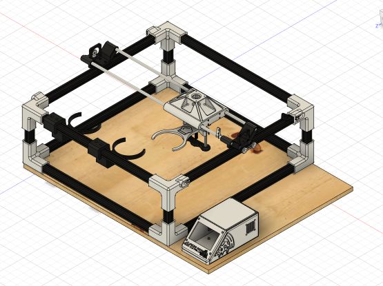
Building and testing the machine
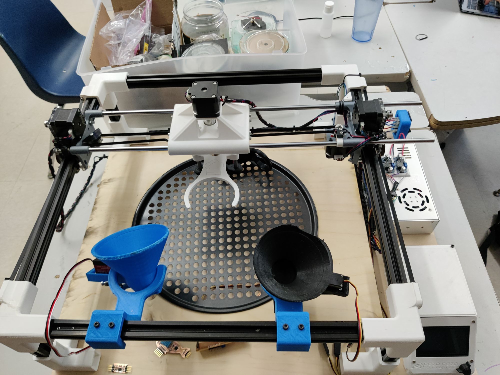
Seeing our machine come together was the best part of the week. We started by using the band saw to cut each piece of aluminum extrusion to the proper size using teddys cut list. During our planning, we miscalculated the amount of extrusion that we were going to need so during the cutting process we needed to make sure that we only cut what was needed. We started by cutting each of the mainframe pieces that needed to be made 488mm. After that, we used the scrape from our 600mm extrusion to make the parts that would hold up the upper frame. We cut each of these to 100mm and then used a mallet to gently pat each of them into their corner that I had designed earlier on. Teddy didn’t get the memo however and ended up cracking on all the way around however it was nothing that some simple super glue couldn’t fix. Once we had the essentials done, we used the extra scrap that we had to create two additional 488mm pieces to help square out the bottom. This simple strategy ended up helping us make sure everything was square for the x-axis since we didn’t have enough for the y axis. Teddy then used a table saw to cut a piece of scrap wood into a base that we would secure the frame and electronics to. The board he chose was warped however so we had to make sure everything was square when we secured the frame down to the bottom using nothing other than hot glue. Despite this sounding like a foolish decision, it allowed us to pull up and relocate the power supply. We mounted the electronics case and power supply on the right side. Teddy used his previous experience in marlin to add games to our machine. Once we had all electronics mounted we started wiring up each system. we started by wiring the x,y, and z motors and testing them. Once we knew that they were working, I started to assemble my two carriages. I was surprised at first that everything fit together and even more surprised when it fit on the machine. We used a mallet to hammer the steel rod into each carriage. When I ordered the rods, I didn’t think to check if they were hardened or not. I ended up ordering hardened steel rods so when it came time to cut them down and prevent a serious overhang, we weren’t able to. We decided to leave them be and focus on other, more important things. Once the entire x,y, and z-axis were assembled we added final touches like and stops, which teddy has an affinity with, to each axis. After hours of assembly, we were able to start working on the actual testing. We started by just running the original home features so that we could make sure everything was moving in sink. At first, the motors were backward but after flipping some wires we got it running. The next issue that we had to deal with was dealing with the belts. Because of the location that we decided to put the tensioners, the belt would get tight when moving to the far sides of the x-axis. When we tried to loosen it, however, we experienced some skipping. We fixed this by finding the perfect median. This took time however but at least our machine could move freely. After we got all the motors and end stops working, we started working on the code. I wasn’t involved in this process at first but after my teammate, Charles had to quarantine because of the virus, I needed to step in. Along with teddy, we working through gathering the exact points for the tool changing. Once we had these points we were able to put them all into the code and test them. It works the first time but after adding some weight to each hopper and continuously testing, we got it working. The next step was to generate the code for the circle. We started by making a simple SVG of a circle in Inkscape and then using cnc.js to convert that into a pocket cut. This could be read by the machine which would perform a spiral pattern. We added this to the tool changing code to get the movement down. We then started messing with the steppers. We started by opening the hopper with a stepper at which point, all the sauce exited in one spot. We slowly worked through it until about 30% was open and the perfect spread was achieved. We did the same for the cheese stepper but since our cheese was expired and warm, it tended to stick to each other. We noted this and then used our hands to move the cheese around until it would fall. We reckon that we could have added a better system that would move it for us but we didn’t think about that ahead of time. After we had everything working, we performed this final test that you can see below.
## Group Site
More documentation can be found on our group site Group Site