Week 11&12. Mechanical Design, Machine Design (Mar 29, Apr 05)
Note: For these two weeks, there are only group assignments and no individual ones
Week 11&12 Group Assignments
-
design a machine that includes mechanism+actuation+automation+application
-
build the mechanical parts and operate it manually
-
document the group project and your individual contribution
-
actuate and automate your machine
Slide and Video
Here is the slide
Here is the video
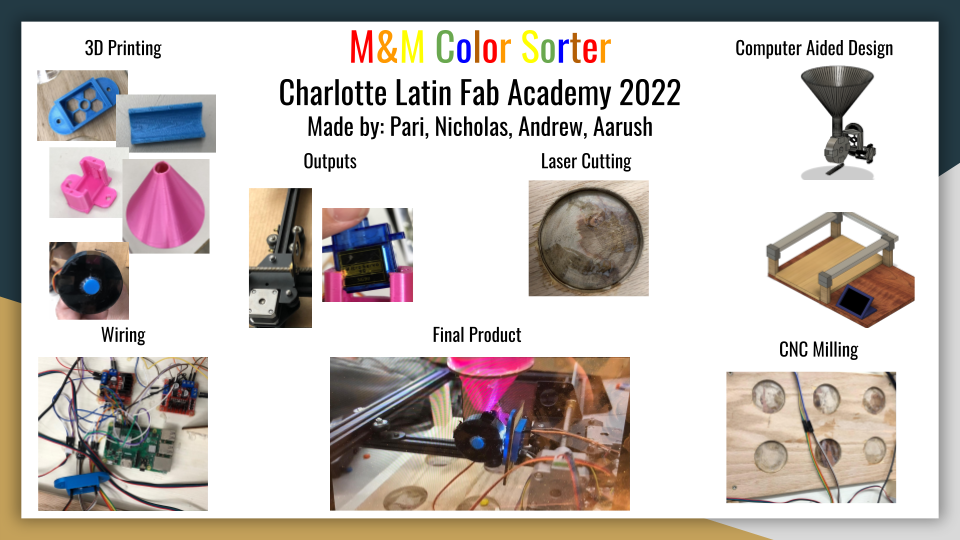
M&M Color Sorter
This week my group consisted of Nick, Pari, Aarush, and I, who worked on trying to build a two axis M&M self sorting machine using a color sensor. Below describes personal contributions. This mainly includes
-
3D designing/printing the parts for the funnel mechanism, with help from Aarush. This includes the funnel, wheel, servo mount, color sensor mount, drop chute. Our entire funnel mech went through three iterations.
-
Working with Pari from FusionCAD, to Aspire CAM, to Shopbot CNC for the wooden bed where the M&Ms will drop
-
Working with Pari to test and get the steppers working as a first step
-
Assisting the design of the fixturing pieces for the funnel mechanism.
Concept
The group originally looked into making some sort of RFID item cabinet, but after this was shot down by the instructors, they went back to the whiteboard and searched for new ideas. Eventually, Pari mentioned the idea of an M&M color sorter. After a bit of discussion, Nick and Aarush drew up some concept images on the whiteboard.
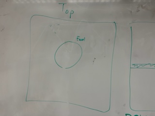
Above is the top view
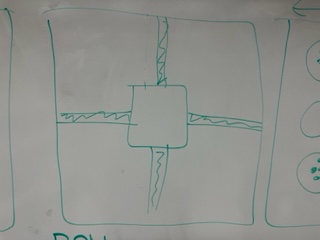
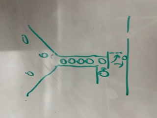
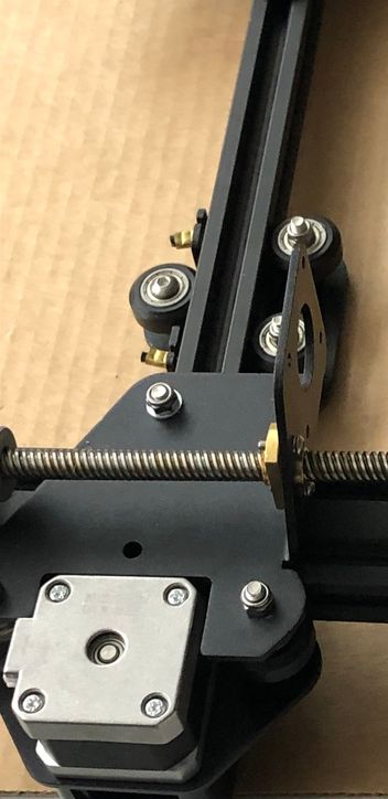
Above is a view of what the machine axis would look like.
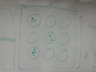
Above is a view of what the bed would look like
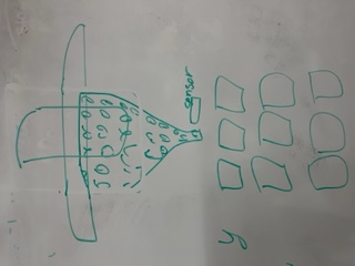
Above is an image of the funnel mechanism
Above is the image of how the M&M will get scanned by the color sensor
The idea was to have a funnel moving on 2 axes with a color sorter and hatch at the end of said funnel. An M&M would fall to the base of the funnel and would be color checked, then the cnc component would move the funnel over top of the hole designated to that color where the hatch controlled via servo would drop that m and m out into its hole and additionally the number of each sorted color would be tracked on a Raspberry Pi and displayed on a small screen.
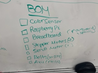
From here, they began creating a bill of materials that would be needed along with the design that had been drawn.
Design Considerations
The M and M sorter would use a few different components: 2 steppers so the funnel could move on both x and y axis as well as a color sensor, all of which would be hooked to the Raspberry Pi. At that time the dropping mechanism was to be a servo motor which would also be connected to the Pi.
CAD and 3D printing
Andrew and Aarush were the ones who worked on CAD designing and 3D printing the various parts for our funnel mechanism, including the funnel itself, wheel mechanism that spins the m&m to get scanned, sensor and motor mounts, and the drop chute to direct the m&m into the hole.
When the plan was laid out, Aarush set to work on designing the funnel that would be used to hold the M&M’s and drop them. From prior design work, Aarush already knew the basis of designing a funnel. In order to send an M&M down the funnel, Aarush made the bottom slot of the funnel big enough to fit an M&M but not too big as to let more than one down at a time.
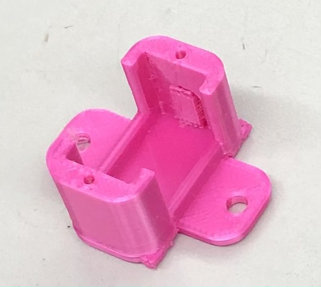
After he finished the initial design of the funnel, Aarush sent the .stl file to Andrew who worked on creating a slot to insert the servo motor and the hatch that would open and close the bottom of the funnel.
Here is an image of the hatch.
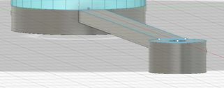
Here is the funnel and servo mount on one file.

Andrew sent this design back to Aarush who fine tuned the design and printed it on his 3d printer at home. Once the file was sent to prusa slicer, however, it was found that it was too long, so, in order to fix it, Aarush scaled the Z-axis down.
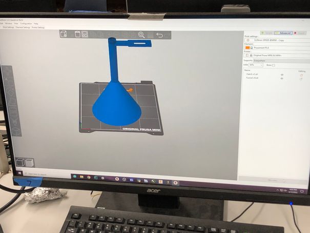
However, due to not having the correct resources for the printer filament, the print failed.
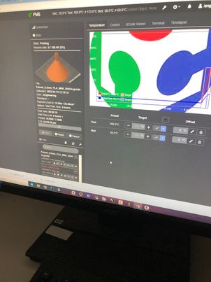
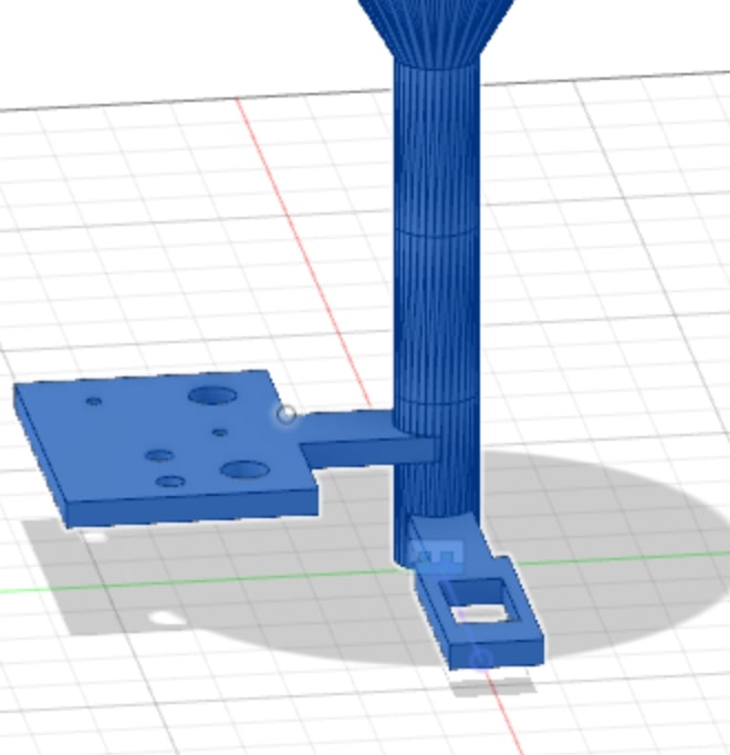
To solve this problem, they waited to print at school but then they were met with another challenge: they forgot the funnel mount. Andrew then worked on designing a mount for the Funnel so that it would attach onto the 2 axis portion of the gantry. He considered the location of the screws that would be needed to mount it onto the actual piece.
Unfortunately, he was not able to print the funnel out because his personal printer had no filament for it, so he waited until he could go back to school and print. In the time when he was waiting, the plan for the gantry changed, in that it was flipped upside down. Also, the group decided not to use a horizontal hatch system and instead use a wheel rotation system of the m&m’s. This was somewhat inspired by this video.
While this didn’t require too many major changes, it did mean that more parts would be added. Although before it was just a hatch and a funnel, now it required a funnel, wheel, and a chute, as well as some mounts for the color sensor and a servo. Andrew then redesigned these parts in Fusion 360 and made everything ready to print.
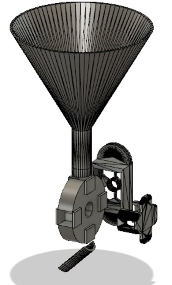
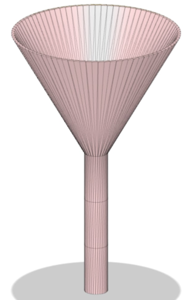
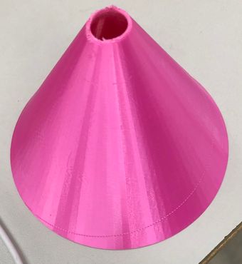
This was the funnel, and as you can see, it’s much shorter than the first iteration design. This is because the object was actually too high to print on the Prusa Printers and it would collide with the top of the machine when printing.

As you can see, this was the wheel design. Andrew, when designing, made sure that it could accommodate an M&M by searching up the diameter and thickness of one. He didn’t have a physical m&m with him so he just found the dimensions online of 1.04 cm diameter and .25 in thickness

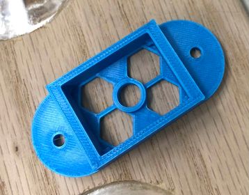
Andrew thought he would look on Thingiverse to try and find a predesigned mount for the TCS3200 Color Sensor, which he found luckily. Here is the credit: KidSwidden’s color sensor
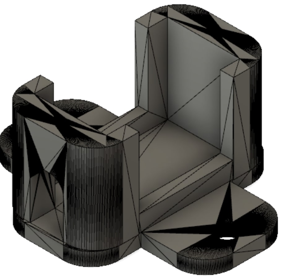
On Thingiverse, he also found a good mount for the micro servo that would turn the wheel. Here is the credit: snblitz’s
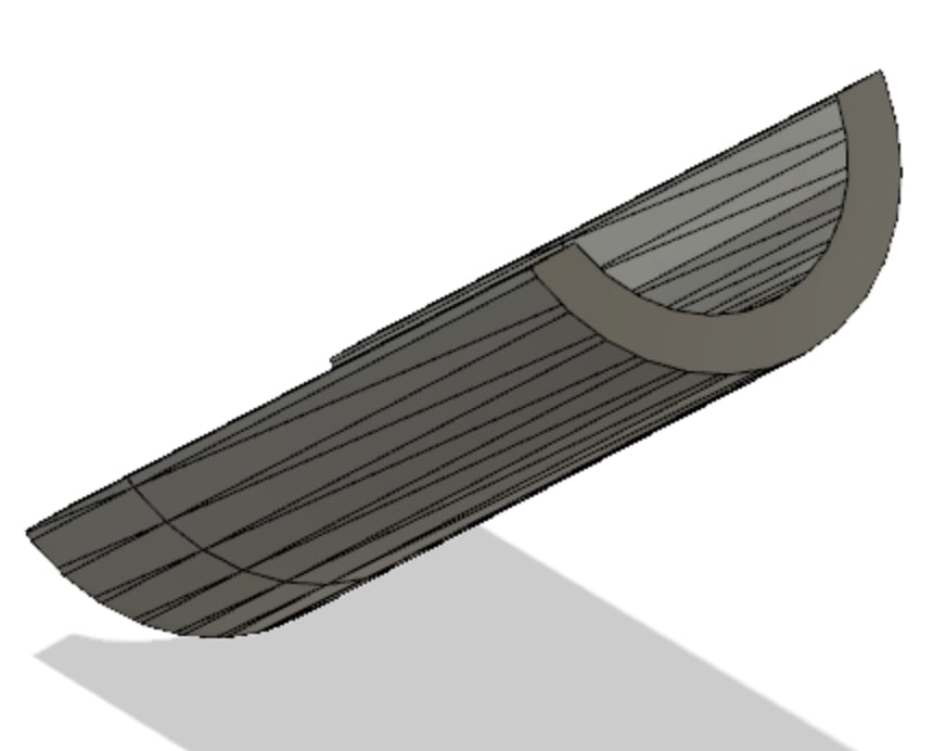
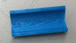
For the chute, Andrew simply took the funnel, and cut the rod piece in half to reveal a slide piece for the m&m.
Now onto 3D printing. For the printing, we didn’t have any major issues since we were using the lab’s Prusa printers instead of our personal Ender 3’s. Our group was planning to print the parts over the long weekend break, but none of our Ender 3’s could be used. Nick’s and Andrew’s printers both happened to be out of filament, and Pari’s and Aarush’s printers were broken.

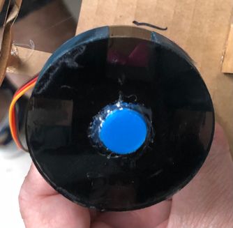
As you can see the 3D printing turned out quite nicely although there are different colors
Stepper Motors
Pari and I began working on the steppers initially where she was able to successfully program and get the motors to move using an l298n motor driver and Arduino. This was mainly just a proof of concept to show we could control stepper motors using the l298n motor driver since none of us had done stepper motors for output week
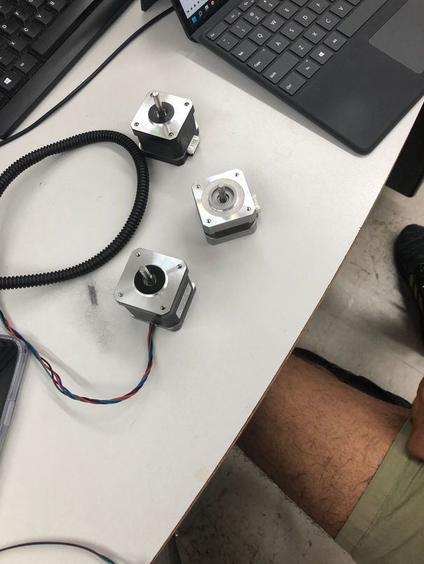
By using a very helpful link Pari followed the step while understanding what concepts it was teaching her. She learned about stepper motors and how they work as she has never used them before. Once following all the steps, with my help, she got the stepper motor to function, which set up a base ground for Aarush and Nick to start the stepper motor and code it using the actual Raspberry Pi.
Later, after Aarush and Nick got the steppers turning with the Pi I discovered that while the stepper motors indeed turned, they turned at an unusually slow rate. After rewatching the stepper motor tutorial that Nick and Aarush had just watched, I couldn’t figure out why this was, so I called Dr. Harris over to help. With Dr. Harris’s help, I discovered the issue, which was that the delay between each motor tick was too high. After making the delay a lower value, I was able to get the stepper motor spinning normally.
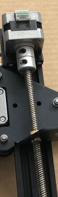
During this process, I discovered that the belt axis was much faster than the rod axis, which made sense because the threaded screw provided more resistance than the horizontal belt.
Wooden Bed
Andrew and Pari were the ones who mainly worked on the wooden bed where the m&m’s would fall onto.
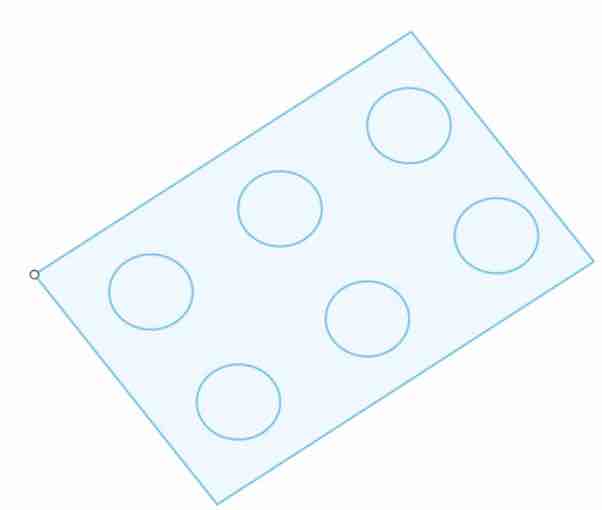
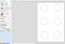
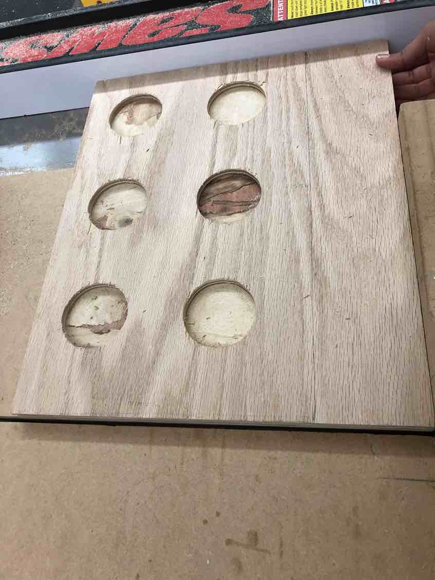
Pari began with designing the file with 6 holes to represent the six colors of m&m’s that the machine sorts: red, orange, yellow, green, blue, brown. She did this using the rectangular pattern tool and doing a 2x3 pattern with the circles in Fusion 360.
Then, Andrew brought the Fusion file into aspire, where he configured the job settings, material offset, and zeroing. The first time he tried to do a pocket toolpath, he zeroed it off of the machine bed, resulting in problems when it was time to CNC.
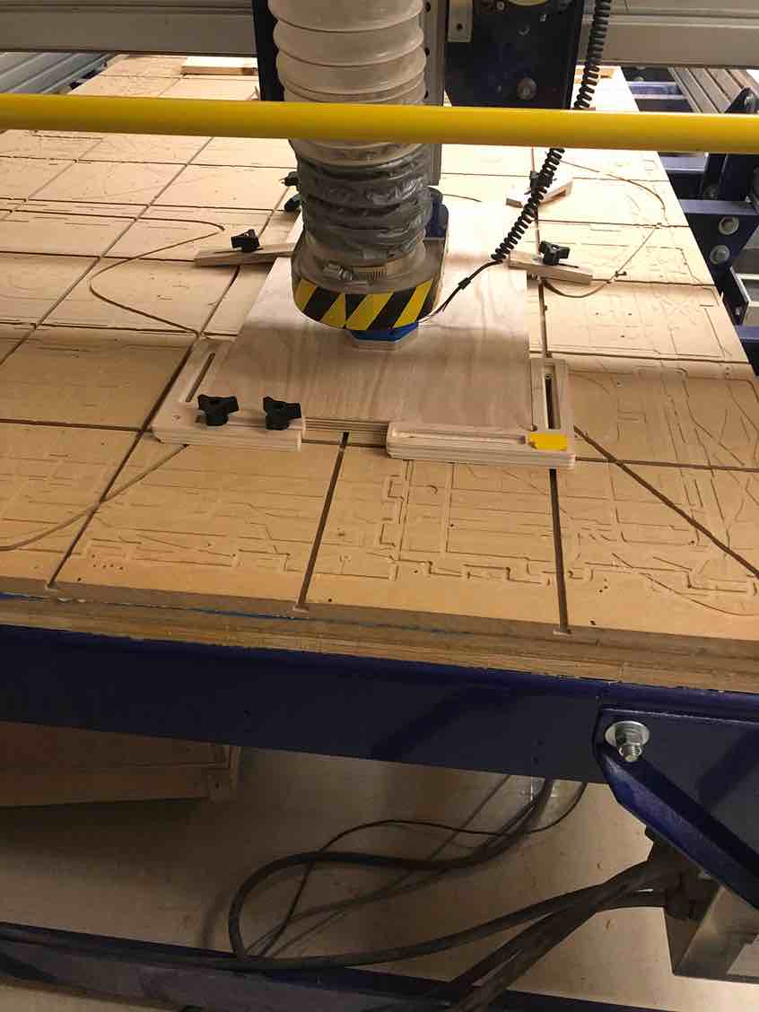
Next it was time to CNC cut. Andrew worked with Pari to clamp the material down using the clamps, something they weren’t very experienced with using. The first time he tried to pocket cut the bed on the shopbot the material came out of the clamps
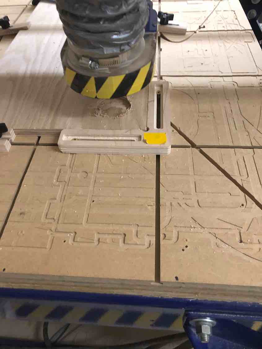
The problem was indeed that Andrew had zeroed the cut off the machine bed instead of the machine surface. Since profile cuts used the machine bed, he had assumed that it was the same for pocket cuts, and was initially confused as to why it was supposed to be zeroed off the machine surface. He did some research and eventually stumbled upon this site that explained the difference perfectly.
Contrary to machine bed touch off, material surface touch off allows the machine to know what it is cutting.
Material surface touch off is used when you need to remove a specific amount of material.
If you were to use material surface touch off, the inverse occurs.
The machine’s reference point gets flipped to where the 0 point is the top of the material.
Now, the machine knows what it is cutting.
With that reference, the machine knows that it has to travel downward .25″, therefore resulting in a .25″ pocket depth.
This explains why pocket cuts need to be zeroed off the machine surface and not the bed, contrary to profile cuts.
With this newfound knowledge, Andrew tweaked the aspire file to have it zero off the machine surface, and worked with Pari to recut. They found success
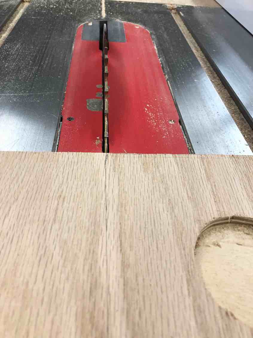
Then, the next issue was that the wood we cut on was too big to fit with our gantry, and we needed to saw some of the parts off. Before using the table saw, Mr Dubick gave Pari and Andrew a brief lecture on two different ways to use the table saw, and then had the two practice sawing
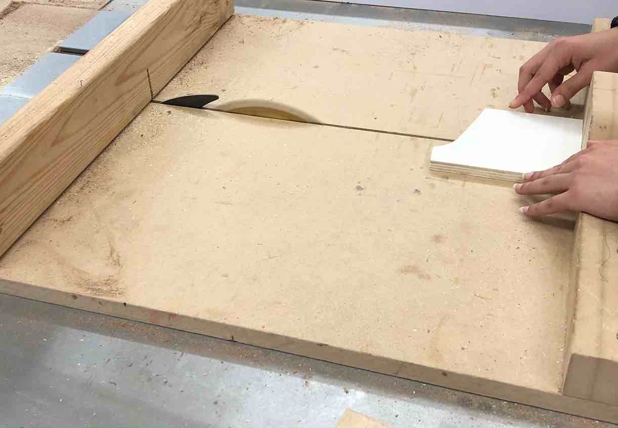
After practicing, it was time for the real deal. Andrew and Pari marked where they were going to saw.
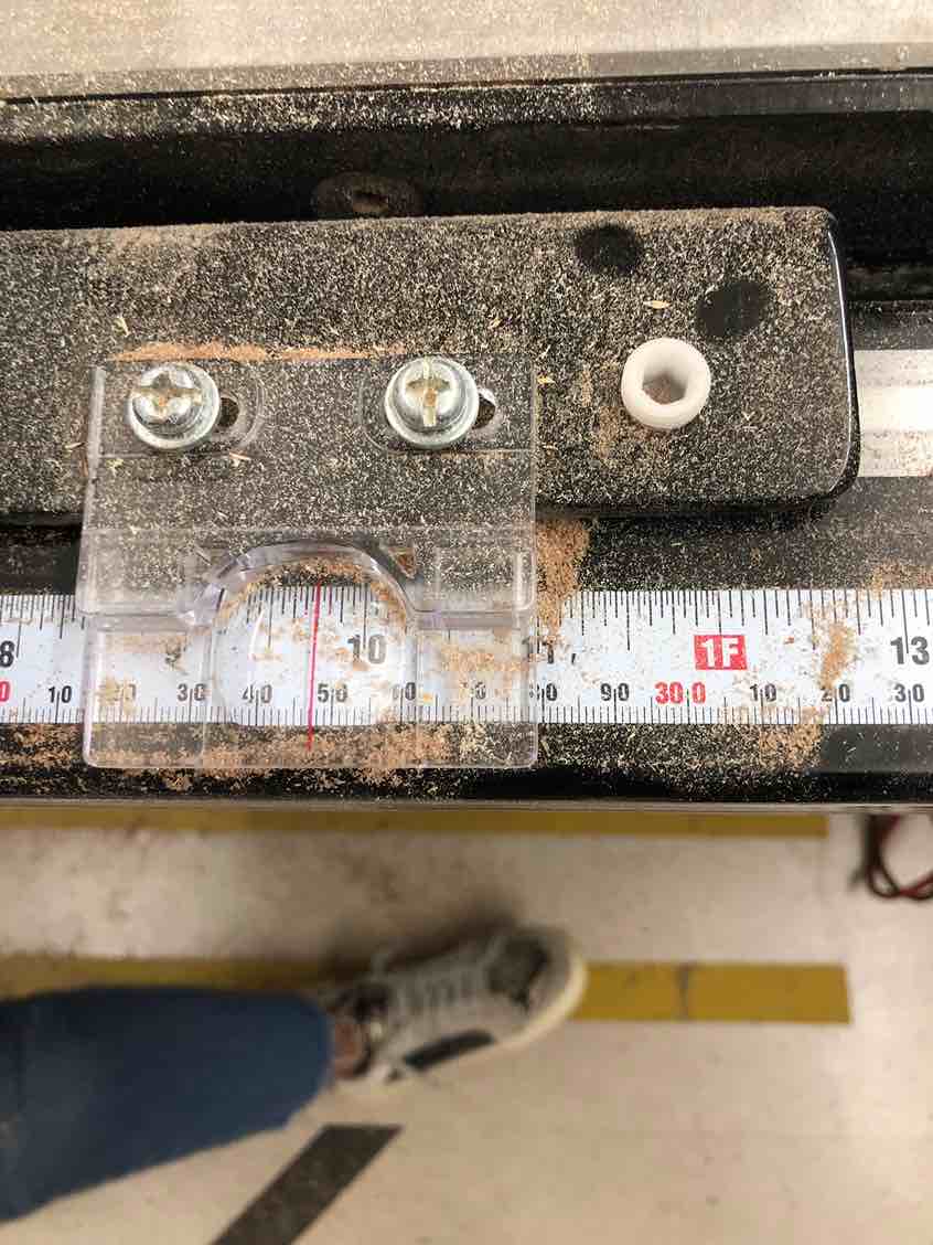
Then they used both of the methods to saw off the excess wood.
Next it was time for post processing, where Pari and Andrew used a combination of sandpaper and a sanding router to smoothen out the wood.
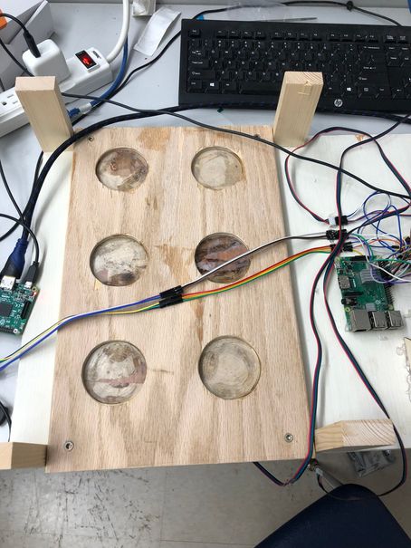
After Pari cut out some sanitary acryllic circles for each hole in the wood, here is the final bed
Week 11-12 Group Site
Note: Here, I will be only linking the site since I talk about my contributions to the group work above
Week 11-12 Files
Click here to access the files I used for this week.