Semi Custom Quadcopter
Final Slide
Final Video
Phase 1: Ideas, Sketching, Research
Sketching and Inspiration
From Weeks 1&2
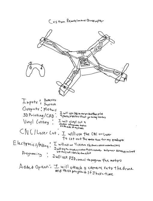
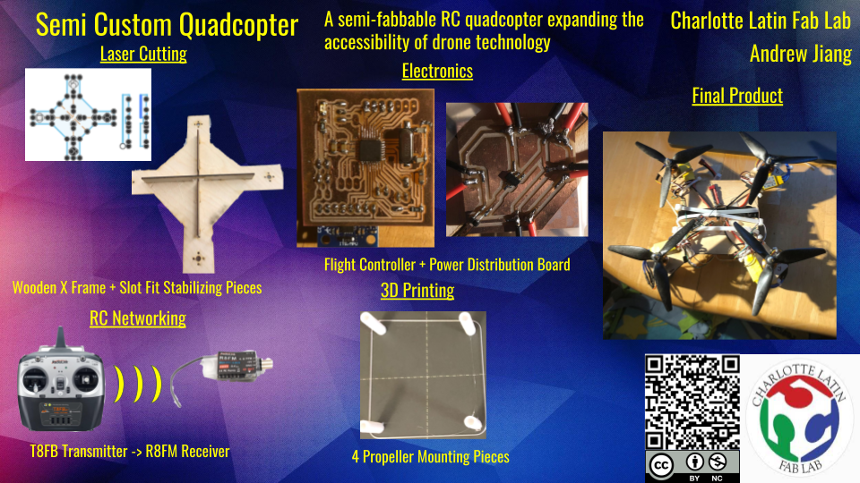
The idea for my final project is to create a semi custom built quadcopter drone that is able to achieve takeoff, and be controlled by an external RC controller. The inspiration for this project was derived from many different sources: my passion for aerospace, the aviation and aerospace engineering class I am currently taking in school, as well as a very interesting and complex Arduino tutorial I spotted before Fab Academy even began. The core idea of my project is that it will be cheaper than commericial drones. This means that it’s more affordable and ultimately improves the accessibility of quadcopters.
After discussing my project idea with Dr. Fagan, another one of my instructors, he advised me to create a plan of what components were needed and how I was going to do it. I first plan on using either the laser cutter, or the CNC machine to cut out the frame for my quadcopter. Then, I will design and mill out a Power Distribution Board, and a Flight Controller, although one of these may come from a kit, depending on my time constraints. Then comes programming, where I plan to use Proportional, Integral, Derivative (PID) control with Multiwii to program the motors. Next, I will 3D design and print custom plastic propeller blade mounts to attach onto my motors. Finally, I will assemble the electronics and the frame together, and test to make sure it works.
CAD Modeling and Sizing Research
From Week 03
I began by doing some research on the most popular quadcopter bases and their sizes, so that I could have a baseline for the size of my custom quadcopter. I wanted my quadcopter to be of a medium size, not too large or too small. If it was too large, it would weigh too much and I would have to get larger motors in order to actually get it off the ground. If it was too short, the frame would be very small, meaning it would be very tough to fit my electronics within the frame.
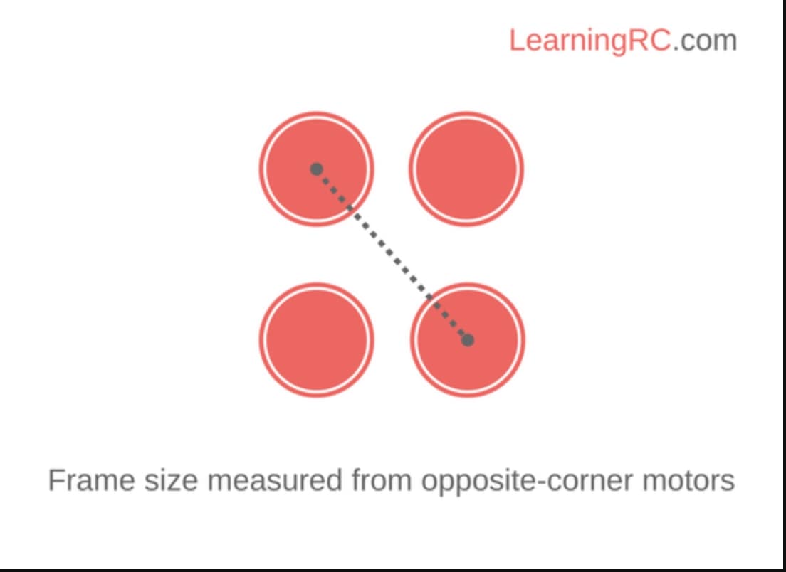
Keeping these size constraints in mind, I started with a google search on quadcopter sizes. This tutorial by Learning RC was very helpful, and I learned that quadcopter sizes are measured from one corner to the other.
Now that I knew how quadcopter frames were measured, I actually needed to decide which size the frame would be. I took a look at a Genstattu blog post and a BotLink blog post “How to Choose Quadcopter Sizes”, and I learned that most quadcopters are between 180 mm and 800 mm long. From this I started thinking in my head about how big I wanted it to be. I originally decided on the frame size of 2 feet (609.6 mm), since I reasoned that this size would allow me to comfortably fit my electronics and not have too much weight. I later changed this frame size to be around 1.25 feet, as I realized that this was a much more attainable goal. For the shape of the copter, I decided to go with a pretty basic x shape as it seemed to be sturdy and convenient. I also knew that I would have a square in the middle of the x frame to serve as a cocoon for my electronics.
Keeping these constraints in mind, I went over to Fusion 360 and started a new file. I’ve seen drones before, but I wanted to be certain that my quadcopter would look close to industry standard. I went to Google and searched “X Frame Quadcopters”. I found a Walmart base design that was similar to what I was looking for.
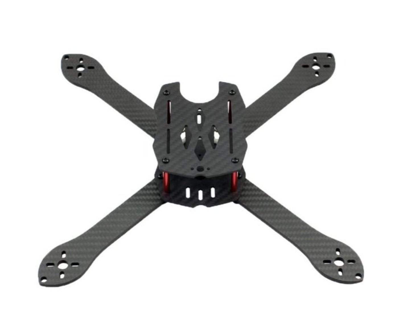
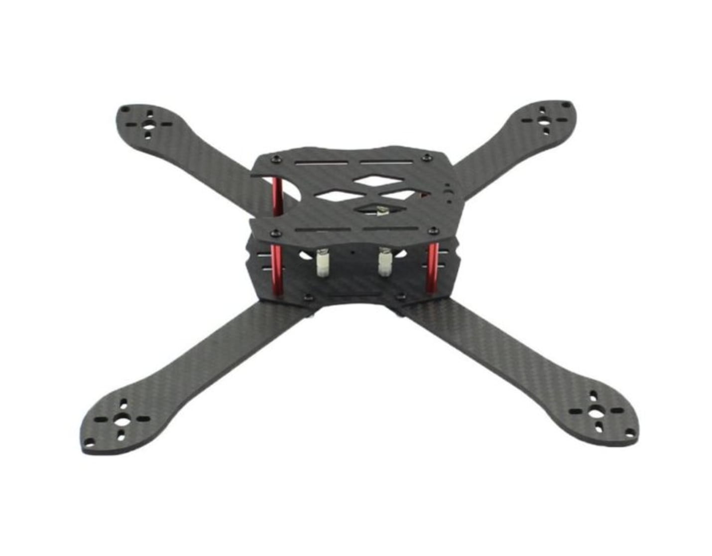
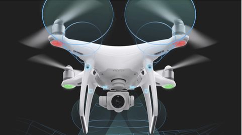
However, when looking at that base, the cage shape in the middle did not appeal to me, so I kept searching for a better model to base my design off of. I found this Drone Rush article about quadcopters of varying sizes, and finally found a design I was looking for: the DJI Phantom 4 Pro V2.0.
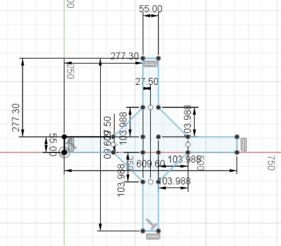
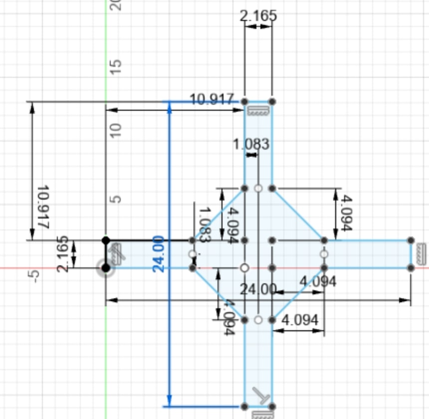
Inside that fusion file, I first created a sketch on the top plane, and drew two overlapping rectangles to signify an x frame shape. The dimensions for the width took lots of trial and error because I just couldn’t get them to look the correct size, but finally I settled on a 55 mm width and 609.6 mm length for each of the rectangles. The next step was to create the tilted box in the middle of the rectangles, which is where I plan to hold my electronics. To do this I first drew sketch points at each of the four corners of the overlapping square, then decided on how far out I wanted the box to be. Again this took trial and error, but finally I decided on about 104 mm, and drew sketch points for that distance to the up/down and left/right using the sketch dimension command. Once I had drawn all of my necessary sketch points, I simply connected them using the line tool, deleted the overlapping lines in the middle, and then redrew those lines to connect everything together. I had finished a base design
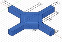
I then proceeded to extrude the sketch outward for a distance of 55 mm so that it would form a square shape on each side.
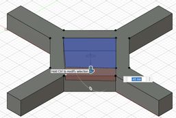
The next step was to design the cocoon where I would sit my electronic pieces into, which really just required a sketched square and reverse extrusion set to cut. I proceeded to do exactly that, repeating the process of using sketch points to design my tilted square. I gave the square about an 150 mm side length, then proceeded to extrude about -45 mm downward into the previous shape. This resulted.
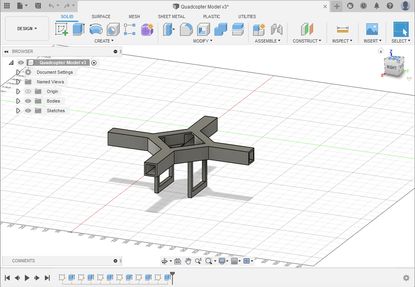
Then, I wanted to hollow out the sides. This would give me ease of access to electronics, ensure the motors could be connected to the flight controller, and conceal my electronics when I was done with the project. To do this, I createed sketches on the right, back, front, and left planes. On each, I drew a second, smaller square over the existing square, and reverse extruded it until the shell was hollow. It resulted by looking like this.
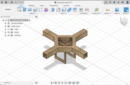
I now had an X Frame, so the next step was the landing gear. The landing gear was a extra addition to the design, and it consisted of two handlebars that ran under the copter. I once again drew a sketch on the bottom of the copter, created two rectangles that were symmetric and even with the two sides of the copter. and extruded them for 152.4 mm (6 inch). I then drew another sketch, this time on the side of the newly extruded rectangles, used the same strategy as the hollowed sides to create smaller rectangle, and then reverse extrude to hollow the landing gear.
The design was almost finished, except for it’s appearance. When I looked at the design, I realized that it didn’t really look like the design I had in my head. After examining, I realized that this was because of the design material. Last week while sketching, I had said I would use plywood for the quadcopter, yet the Fusion design was not in plywood. To solve this I pressed the “s” key for shortcuts, and typed in appearance to bring up the appearance menu. Finally, I simply searched up wood, dragged an option from the appearance menu to the design, and it looked like this.
The design was complete.
Phase 2: Subsystem Construction
Frame
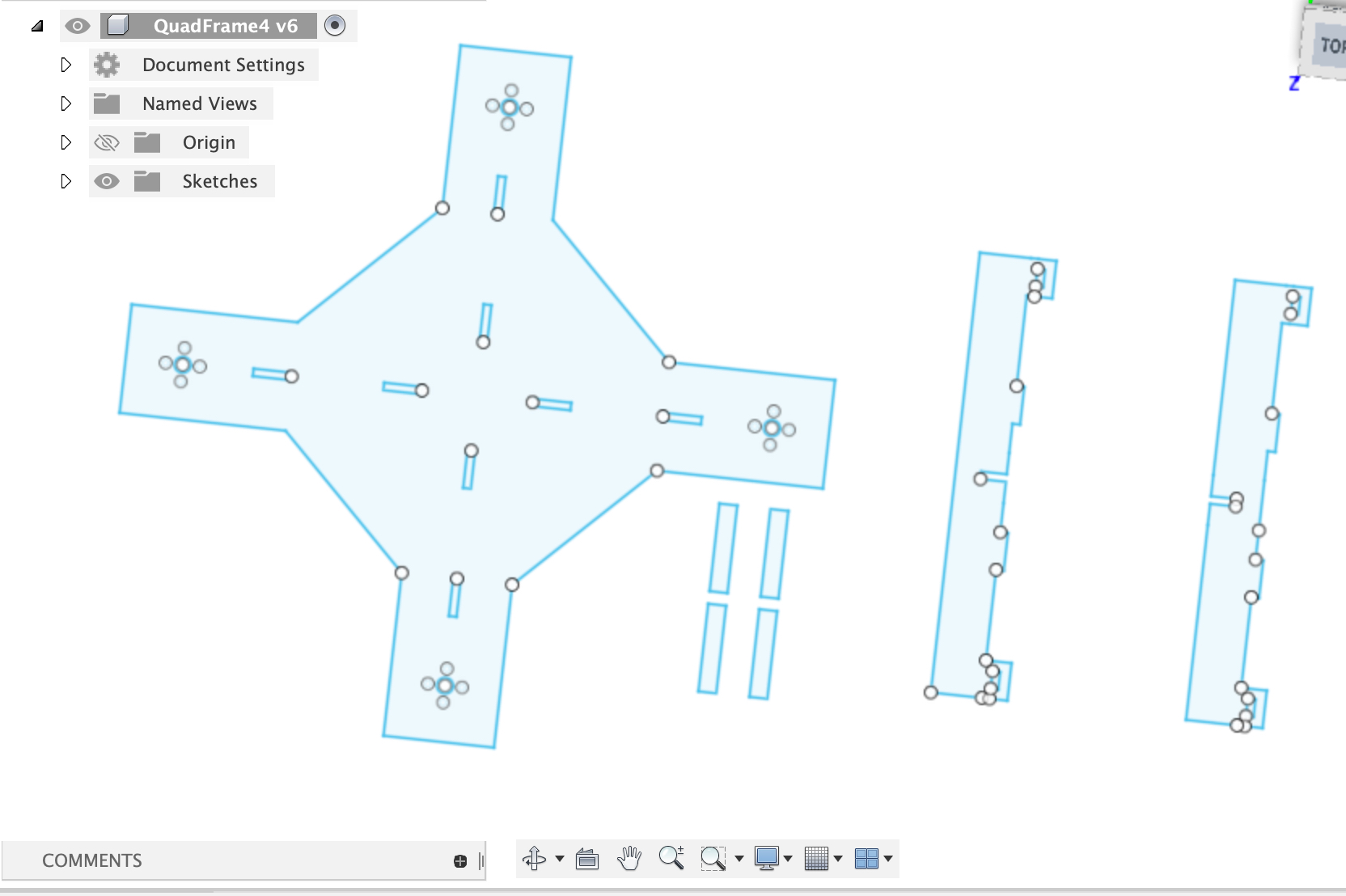
I started off by basing the frame design for the laser cut on the quadcopter model I designed in Computer Aided Design week.

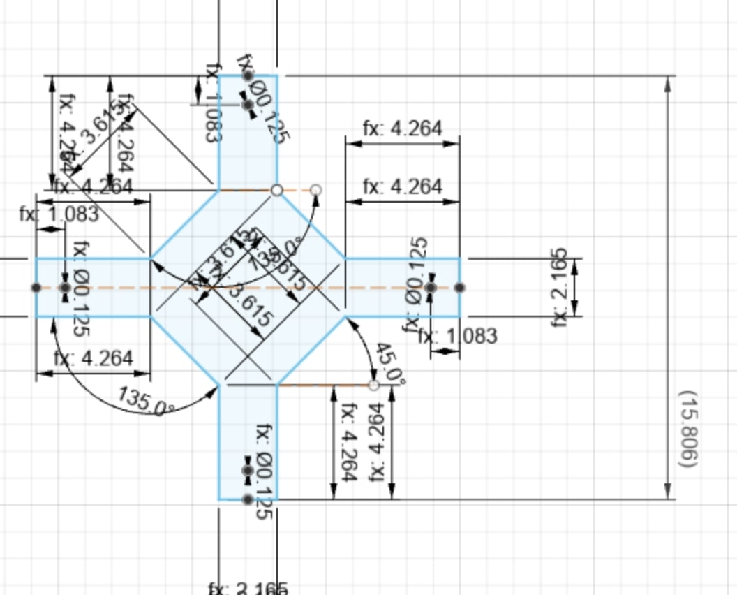
In CAD week, I designed the quadcopter to be two feet across the diagonal since I didn’t know what an appropriate size was yet. Now I wanted to shrink this substantially to make it a more manageable size, so I shrunk the design so that it was 1.25 feet across the diagonal. I did this using the sketch scale design feature in Fusion 360 accessed under Modify->Sketch Scale. Here you can notice that I haven’t addded holes for the motor mounts to this design, since I wasn’t sure of the correct positioning yet.
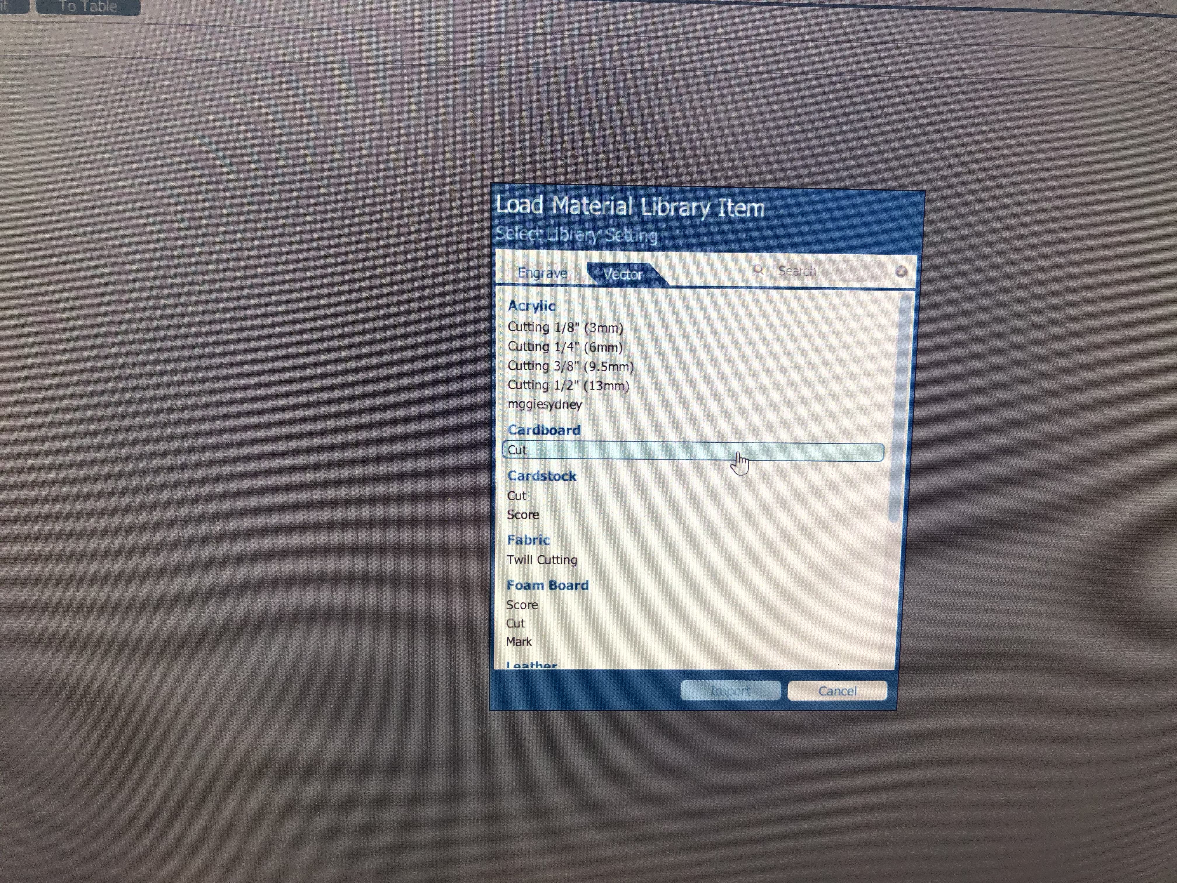
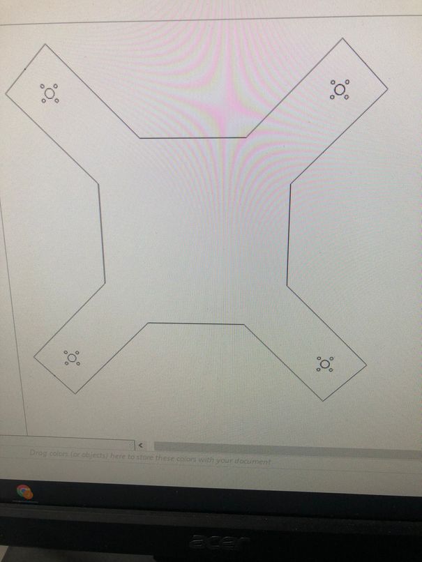
Then I went to laser cut, first testing the design on cardboard. I exported the Fusion 360 file as a .dxf, then brought it into Corel Draw, making sure everything was hairline. Then I hit File->Print, checked that there were no issues, and configured the frequency, speed, and power settings of the Epilog Fusion laser cutter.
This led to the laser cut of my first prototype frame
After cutting it out, I then needed to add motor mounts to the design. Again I did this in Fusion 360.
Then I once again brought the design into Corel Draw.
This was the second prototype of the laser cut, with the motor mounts.
Once this one worked, I was feeling pretty confident with the frame design, but I still wanted to make it smaller. To do this, I didn’t use sketch scale, but just changed a parameter since I didn’t want the whole quad to shrink, but just the sides. Then I tested this laser cut on cardboard once again before trying to transition to wood.
As you can see, the laser cut burnt through the cardboard with the motor mount, which had never happened before. This happened since I realized that I had not accounted for the laser cutter kerf. I found the kerf value of the laser cutter, 0.012 in, from our group work, then added that to the distances. Next I performed another test cut, which was successful since nothing burnt up.
Here was the result of that cut.
Next, I felt ready to tackle laser cutting the wood. I simply imported the settings for 1/8 inch wood instead of cardboard this time. This was the product.
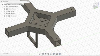
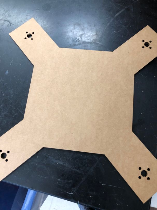
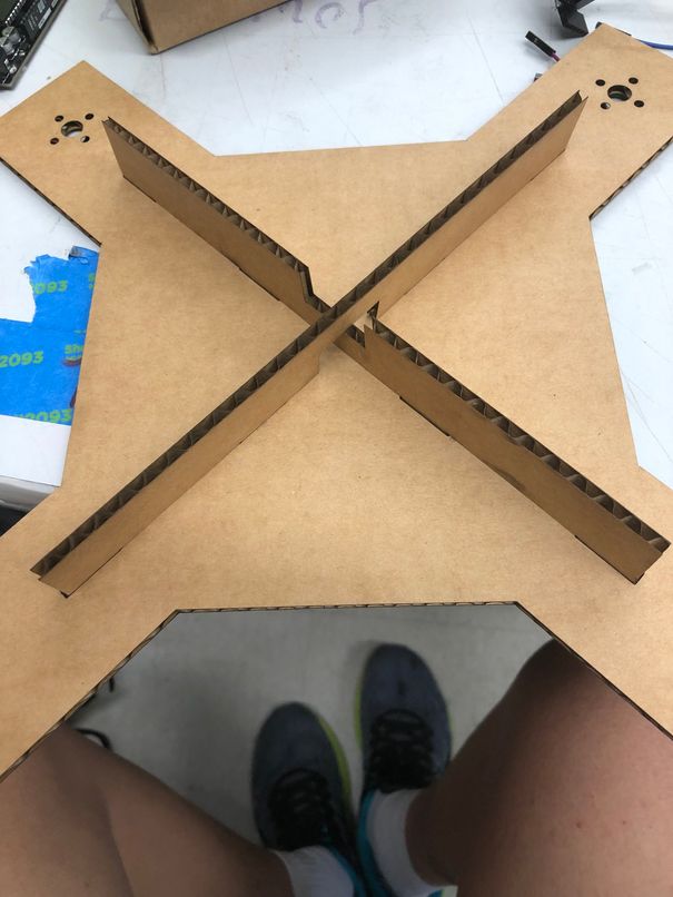
However, the problem with this frame was that it just wasn’t structurally sound. Even with the wooden frame, it was way too bendable and, as Dr. Fagan pointed out, it wouldn’t hold up with the shaking of spinning BLDC motors. He then recommended that I add two slot fit pieces going across the diagonals of the frame to make it less bendable and more rigid, which is then exactly what I did. This idea was somewhat inspired by this instructables. Here is how the final drone frame design looked.
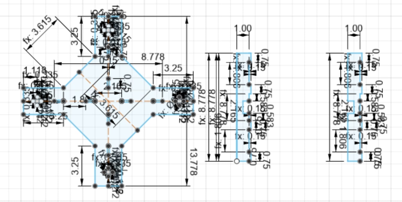
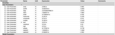
As you can see I’ve added press fit tabbed pieces in the design to improve the stability of the quadcopter frame. I also remembered to account for kerf with all the slots being cut out. This ended up being the final version of my frame design and here are all the parameters I used.
Again I first performed a test of the new V3 frame design on cardboard.
Once all the pieces were cut out, I fit them together, and they fit together perfectly.
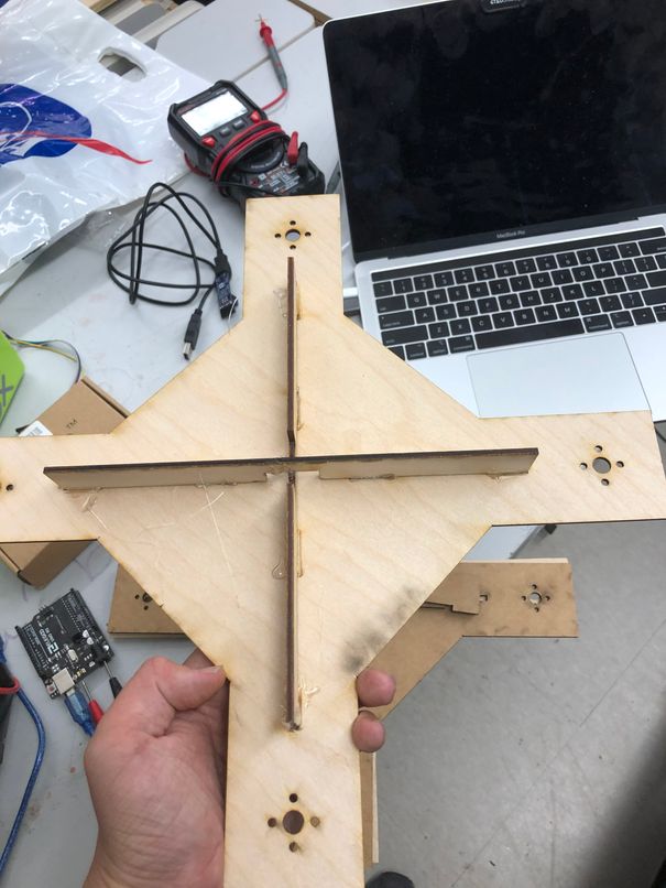
Now it was time to do the final cut on wood, where I simply imported the wood laser settings instead of the cardboard one on the Epilog Fusion Pro Laser Cutter. I didn’t have to change the design to account for the wood thickness since the wood I was using (4 mm thick) was very close to the thickness of cardboard (0.15 inch thick), but was a lot more dense and sturdy. Here is me cutting the design out on wood.
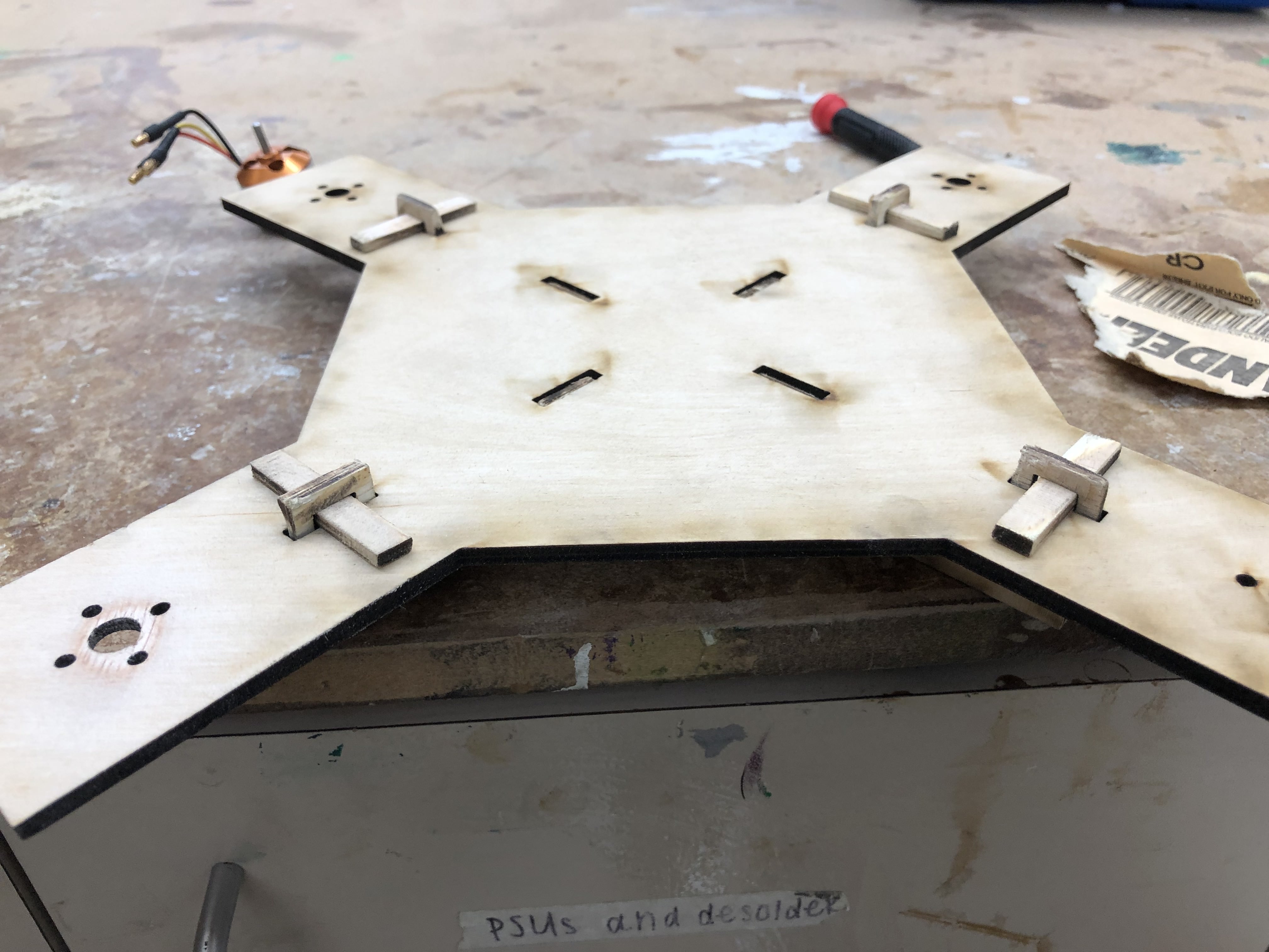
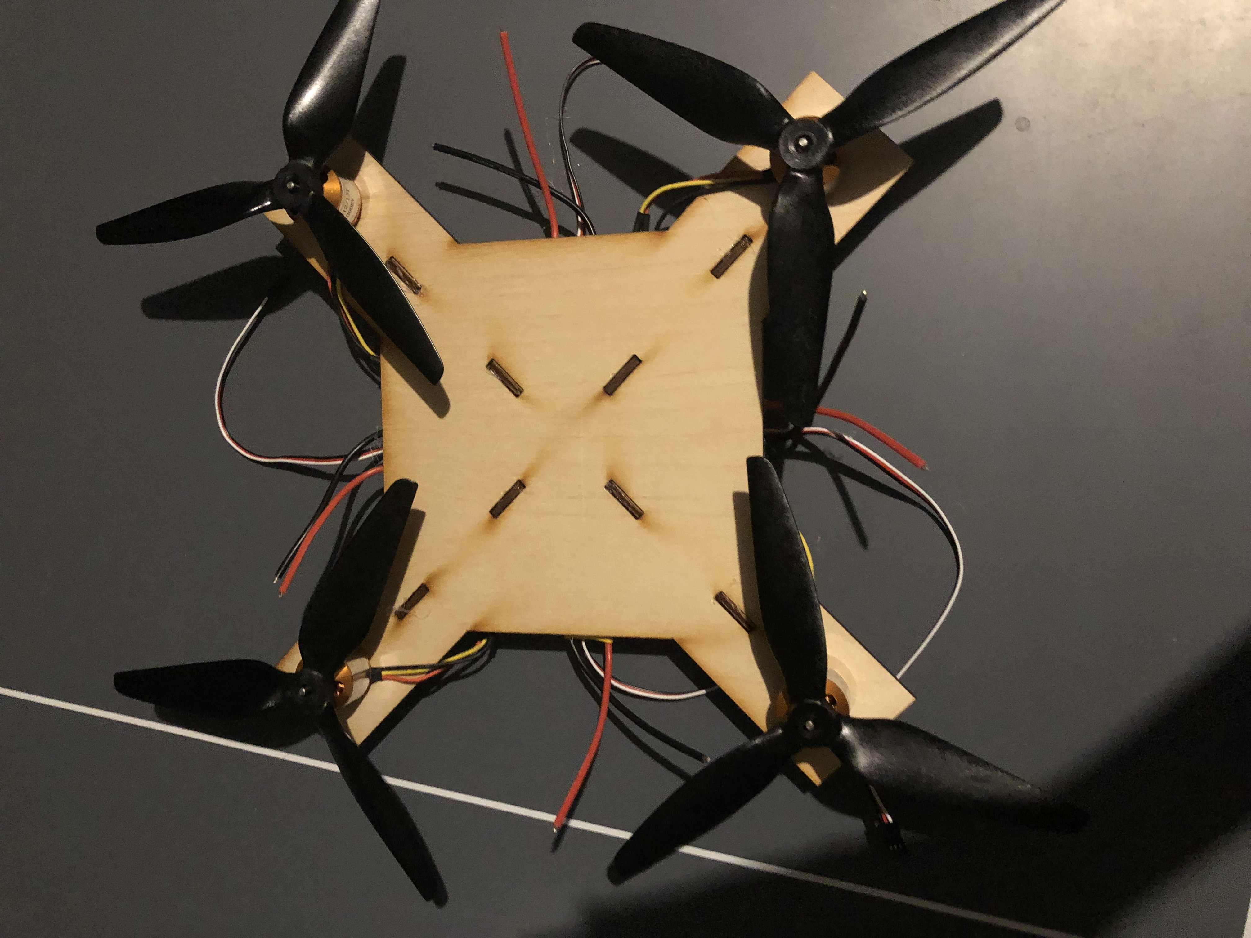
Here’s how the frame looked, after hot gluing the pieces together. As you can see, the frame has much more stability than the first few iterations.
Finally, I decided to make a more reinforced frame, better than all the previous versions. I designed this frame with an idea from Dr. Taylor, which was to add more slot fit pieces and thus eliminate the usage of glue.
I first did a test cut on cardboard
This was the result
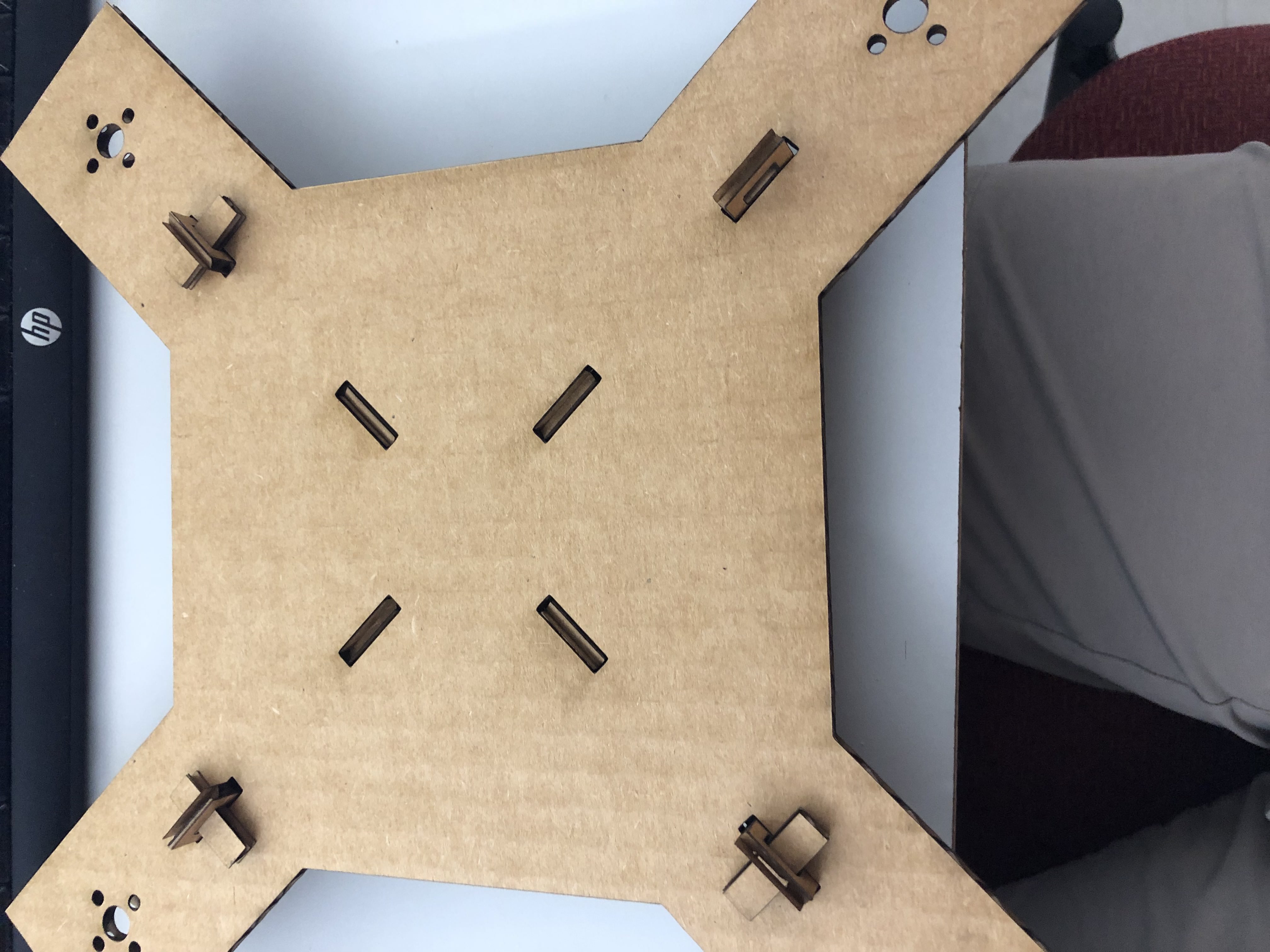
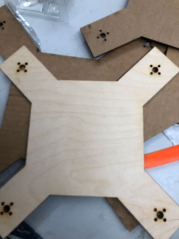
Then I did a cut on wood, which ended up being a final version
This was the final frame, which is all press-fit.
Flight Controller
Version 1
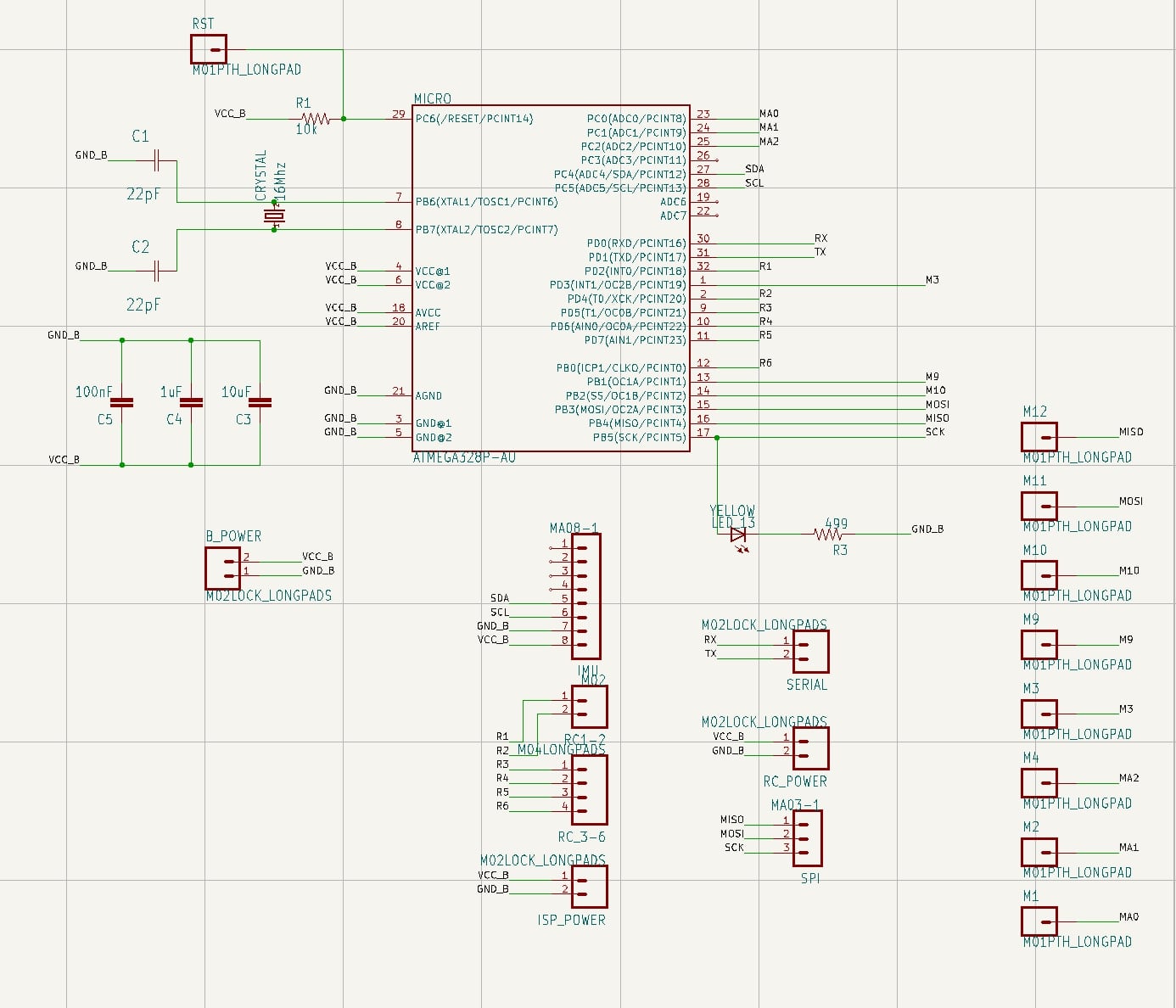
For the flight controller, the main control board for the motors and the project as a whole, I modified the satshakit flight controller created by Danielle Ingrassia to fit my own project. Since the flight controller included an embedded power board, I was initially planning to use that, but then I found this sentence in the documentation
For drones up to 4 motors and 15A ESCs, is possible to use the embedded power board, otherwise is recommended to use an external power board, and to make the satshakit flight controller without the power board embedded.
Since I would be using 30A ESCs and 4 motors, I reasoned that the embedded power board was not a good idea, and that I would make my own power distribution board, using the battery to power the ESCs with a 5V regulator to power the flight controller and receiver.
Thus I first imported in the satshakit flight controller schematic, which looked like this.
Then I imported in the satshakit flight controller pcb layout, which looked like this.
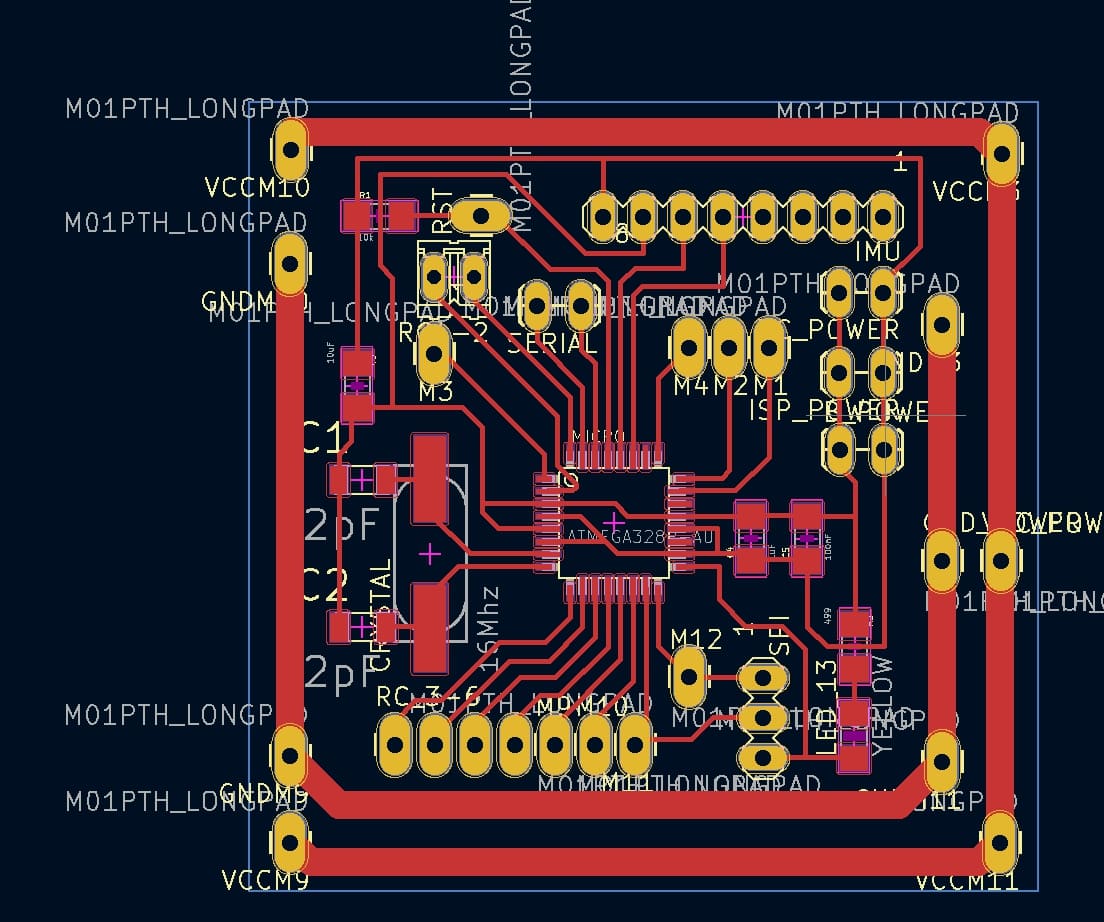
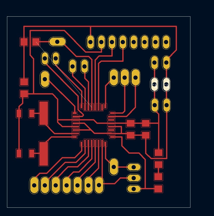
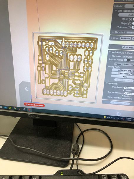
As mentioned prior, I wanted to get rid of the embedded power board, so I removed those two traces from the PCB design. I also added a border around the traces in the edge cuts layer. The PCB design looked like this.
After exporting the design as a F.Cu gerber, Edge Cuts gerber, and a drill file, I went to go mill out the PCB design. By this point I was pretty familiar with PCB milling, and I simply followed the same processs as always. A more detailed documentation of PCB milling can be found in Week 05: Electronics Production. I made the trace clearance 0.35 mm and trace depth 0.3. Looking back on it now, I should have made the trace clearance much larger so that no excess copper would remain on the board, and be prone to causing a short. Below are some videos/pictures of the process.
Here’s what the design looked like in the Bantam Tools milling software.
Here’s a video of me locating the 1/64 end mill bit.
Here’s the probing material thickness with the 1/64 end mill.
Here’s the location of the 1/32 bit after the 1/64 milling
Here’s the milling using the 1/32 bit
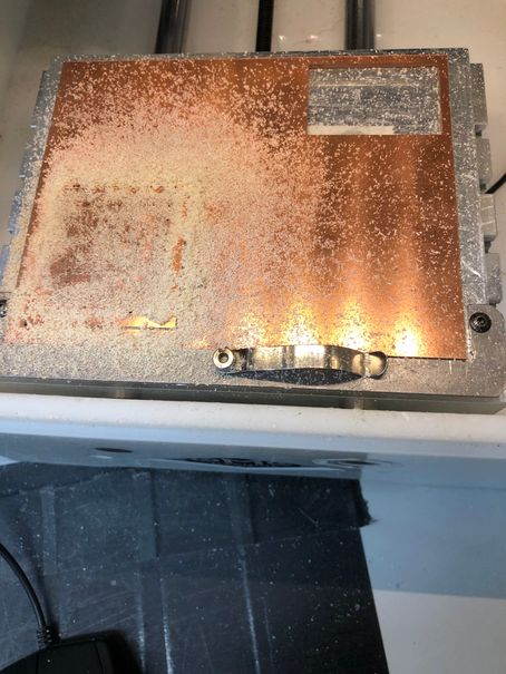
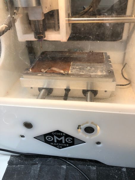
Here’s how the machine looked after the milling finished.
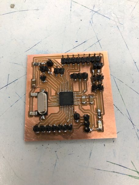
Next it was time to solder on the components. The components used for this board were
-
1x ATmega328p chip
-
Male THT headers
-
1x 16 MHz crystal oscillator
-
1x 10k ohm resistor
-
1x 499 ohm resistor
-
1x red SMD led
-
2x 22 pF capacitors
-
1x 10uF capacitor
-
1x 1uF capacitor
-
1x 100nF capacitor
Here’s how it looked after soldering
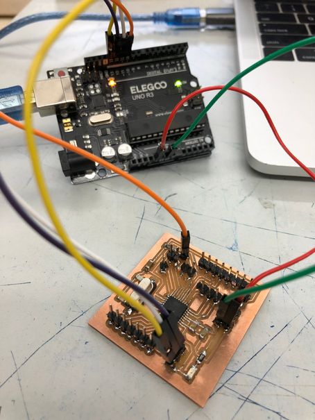
Next it was time to program the satshakit. First I would need to burn the bootloader, which would turn the Atmega328p chip into programming mode. To do this, I would need to turn an Arduino into an ISP programmer, and then use the ISP connections to upload the bootloader onto the chip. First I tested that my arduino wasn’t broken by uploading a simple blink sketch onto it.
Then I uploaded the ArduinoISP sketch to the Arduino Uno, making it an ISP programmer. Next, I wired up the VCC, GND, MISO, MOSI, RST, SCK pins of the Arduino to the satshakit, which looked like this.
Then I went to Tools, chose the programmer as Arduino as ISP, and then hit burn bootloader. The first time I received this error about the device signature being 0x000000. At first I didn’t know what that menat.
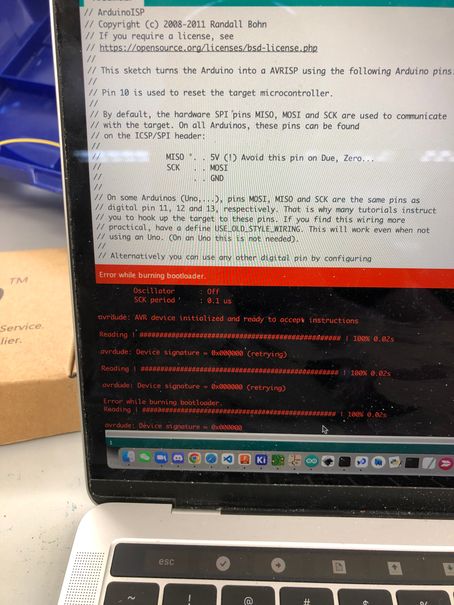
After consulting Dr. Harris and researching the error online, I found this resource, which said that a potential cause of this error may have been that:
One of the SPI pins was shorted to ground
Then, I took a multimeter and did continuity tests all throughout the board, sure enough finding that my MISO pin was shorted to ground. After removing the solder bridge and trying to burn the bootloader again, this time with a Atmel ISP/FTDI development board, the bootloader was finally burnt.
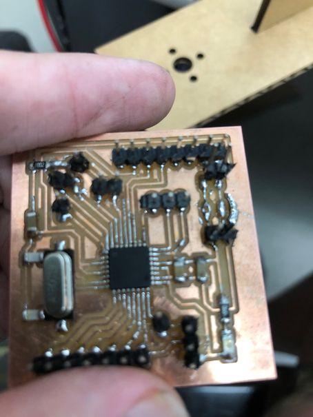
Unfortunately, what happened was that I ripped a critical power ground trace when trying to take a header off. This was my fault once again, since I had soldered the male THT headers onto the front of the board instead of the back, which made the headers very unstable and easy to rip a trace off, which is unfortunately what happened. Having no other option, I had to remill the board once again.
Version 2
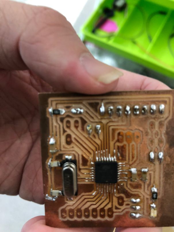
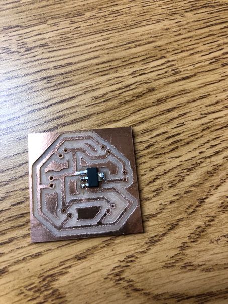
For the second version of my flight controller I was determined not to make the same mistake as I had on the previous one. After milling and soldering (following the same process as the previous one), the board looked like this.
Next it was time for programming. I did the same thing as I had done with the previous one: turned my Arduino into an ISP programmer, then wired up the connections, and tried to burn the bootloader. Once again, I received the error of the invalid device signature, but this time it wasn’t all 0s like the last one. When I tried burning the bootloader agian, the signature changed even though I had done nothing differently. This time, I decided to ask for Dr. Harris’s help, and he gave me these three options.
-
Use a programming socket for the Atmega328p chip, meaning I would need to take the chip off the board, program it, and put it back on
-
Use surface mount clamps to do the same thing, program the chip then put it on
-
Take a surface mount Atmega328p with the bootloader already on it from an Arduino
I deicided to try the first option initially, meaning I would have to desolder the chip from my board. I used a high temperature reflow heat gun to try and take it off, but the chip wouldn’t budge on the board. At this point, I decided to try burning the bootloader once again, just to see if anything changed. I cleaned up some dirty traces which had excess copper left with some tweezers, and to my surprise, it worked for me in trying to burn the bootloader. I think that the dirty traces were causing shorts between the SPI and GND pins, since I had noticed that those were shorted together when I checked continuity with a multimeter.
After I burnt the bootloader, I worked to get the multiwii code uploaded onto the flight controller. I first took a look at this arduino flight controller tutorial. Then I went to the MultiWii website to get the Arduino code for the Multiwii GUI.
I encountered some problems when trying to open the MultiWiiConf program on a mac. This error kept showing up.

I tried a few different methods to debug the issue. First I found this apple help site that seemed to address the problems that I encountered: that I somehow didn’t have permission to open that app. I went into the app file, accessed the sharing and permissions, and changed them to “read and write”. However, the problem still persisted.
The next thing I tried was searching the error up online to see what other people did to solve the issue. During my research I found this stack overflow forum post that seemed to relate to what I was experiencing. I tried the solution of editing the app file itself, which had me resign the app using sudo, move the app to quarantine, and then make the file inside executable. After all these steps, it still did not work to open the app
The last thing I tried was trying to open the MultiWii GUI on processing. I found this flitetest tutorial online that detailed each step of the process. I followed the steps to open the Multiwii program in processing, import the controlP5 library, then export the application to open it. Finally the interface showed up, but I soon realized that I couldn’t edit the interface in any way whatsoever, and everything was red. Thus this method didn’t solve my problem either.
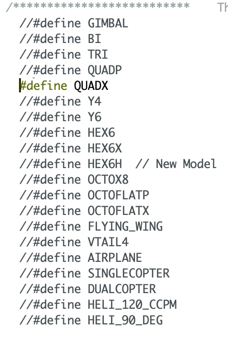
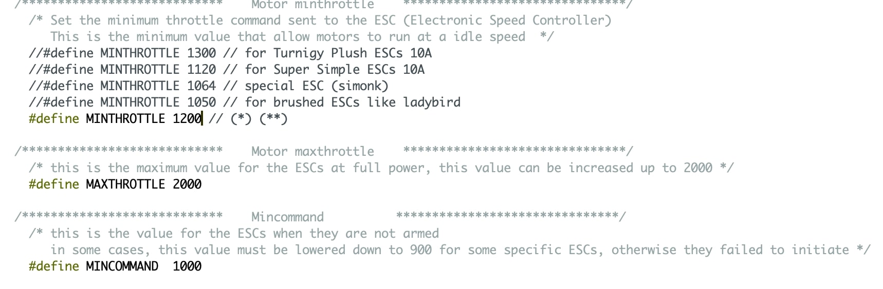
Thus I decided to ask Dr. Harris for help, and he informed me that the Multiwii GUI would only work on a Windows computer. With this info, I started trying to modify the Multiwii arduino code to fit my quadcopter. I found this arduino tutorial online which showed the steps for modifying the code. I first uncommented the QUADX definition in Multiwii, since I was doing a quadcopter with an X frame orientation.
Next, I changed the min, max, and normal throttle values to more accurately match my specific motor.
After changing the code, the last steps involved soldering the IMU onto the flight controller and then testing the multiwii code on the finished flight controller. Here’s what the flight controller looked like after the IMU was soldered on.

Finally I had to upload the flight controller code onto the board. I plugged in an Arduino into a windows computer, converted it to an ISP programmer, and then wired up the ISP connections from the Arduino to the board. Then I ran the multiwii code which was worked in the Multiwii GUI. As you can see in the video below, the sensor values respond to changes in the IMU’s movement.
This demonstrated that the flight controller worked, which was a big breakthrough in my project.
Power Distribution Board
Version 1
For the power distribution board, I spent a lot of time pondering whether I should use a commericial one or just make one. In my head, the concept was pretty simple: just have a few connected power and ground traces which all run to the battery. Ultimately, I decided to do some research on them first. I found this video below by Joshua Bardwell which explained the power wiring of a flight controller.
I also found this video by Robojax which explained the difference between different commercial power distribution boards.
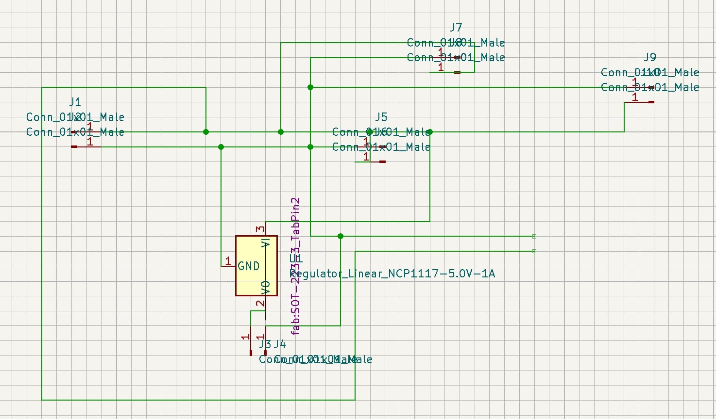
From these videos I identified that a power distribution board could be complex, but it could also be incredibly simple. Since I’m only doing the first spiral, I wanted my power board to be fairly simple and only contain the necessities. I went to draw up a design in KiCAD. Here is the schematic.
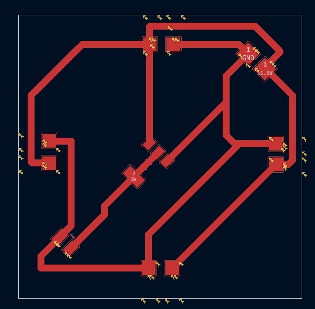
Here is the PCB layout design which I did in PCBnew. I used through hole pads instead of surface mount here since this allows me to directly solder an ESC wire into the hole.
The components of this board I’m using here are
-
6x 2 pin THT header holes (4 for ESCs, 1 for battery, 1 for FC)
-
1x 5V regulator (to regulate the voltage going to the flight controller since the full 11.1V battery voltage would fry the FC)
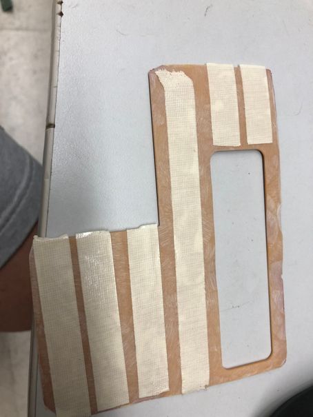
Once I finished designing the board, I went to go and mill it out. Unfortunately, it turned out that our lab had actually run out of single sided copper boards, and so I had to turn to using double sided PCB boards to mill. However, with my design containing through hole components, a double sided board would not work. Thus, my only option was to sand down the copper on one side of a double sided board, which would turn it into a single sided board which I knew how to mill. At first, I tried using sand paper and a sanding router to sand it, which did nothing except scratch the copper, which is not what I wanted. Then I consulted fellow student Jack Donnelly, who had just milled out his board, and he told me that I should use the belt sander because it had such a high torque and it was way easier to sand. This is what the belt sander looked like.
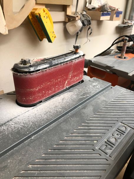
For this step of the process, I wore both a mask and eye protection because I had been warned by Jack that there would be tons of copper shards being sanded off. Then, I turned on the sander, and pressed the copper sheet against it. After ~10 minutes of sanding, I had finally managed to get all the copper off the back side of the board. Then I used the vacuum to suck up all the copper shards which had gotten on the tool, on the board, and on my hand. Finally, once the board was clean, I put nitto tape on the back of the board. It looked like this.
Next was the milling process, where I used a 1.75 mm trace clearance, 0.3 trace depth, 1/32 and 1/64th bits to do. Here are some snippets from the milling.
Here is what the board looked like stuck onto the bed
Here is me locating the 1/32 flat end mill tool after using the 1/64 end mill already.
After milling, then came soldering, which was pretty straightforward since I only needed to solder the 5V regulator for now.
Here is what the PDB looks like with the regulator on it.
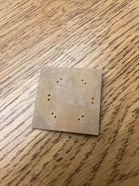
Here is the result of the sanding on the back of the PDB
Unfortunately, I realized when trying to solder on all the ESCs, that the board I had made was too small. It wasn’t large enough to be able to connect all the ESC wires up to it simultaneously, rendering it a useless board. Thus, I had to make another power board.
Version 2
For version 2, I approached the problem of making a power board, with a better understanding than last time. The whole reason that the power board was too small last time was because I had not done proper measurements on the frame, which at the time had also not been finished yet either. With a finished frame, this time I could truly make some proper measurements to determine how big I needed this board to be, and how thick the traces needed to be.
Firstly I wanted to find out how large the board should be to be able to wire up 4 ESCs, 1 battery, and a two pin header. To do this, I did some measurements/sketching on the finished wood frame. I also used callipers to measure the distances, which is a very precise tool compared to a normal ruler.
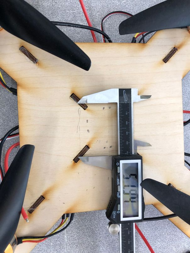
Once I measured out exactly how large the board should be (~ 52 mm x 52 mm) and the thicknesses of the ESC wires/battery wires, the next step was to consider how thick I would need ot make my traces in the KiCAD design. In the past when doing electronics design, since I was always working with low currents, I never had to worry about a specific trace width, and would always just make them as large as the board could hold to make soldering easier. This time however, considering the trace width is absolutely a necessity since the power board will need to hold 30 A of current and distribute them to the ESCs. From my research I found that if I hadn’t considered this factor, according to this site, then it could lead to the board warping, layers peeling, and cracks developing.
To measure the width of trace needed, I used this online calculator, which asked me to input in the desired current and trace thickness values. I didn’t know what the trace thickness of the copper sheet was, so I looked it up online here. After inputting in the required values into the calculator, I determined that a 1.75 mm copper trace would be able to handle the 30 A current coming from the battery. Just to be safe, I wanted to make the traces 2.25 mm wide. I took this information and started designing a new PDB.
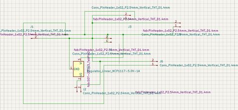
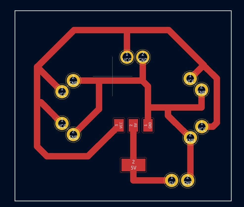
After finishing both the PCB and schematic design in KiCAD, here’s how the designs looked
I took these designs to the milling machine, where I milled the board out of a sheet of copper.
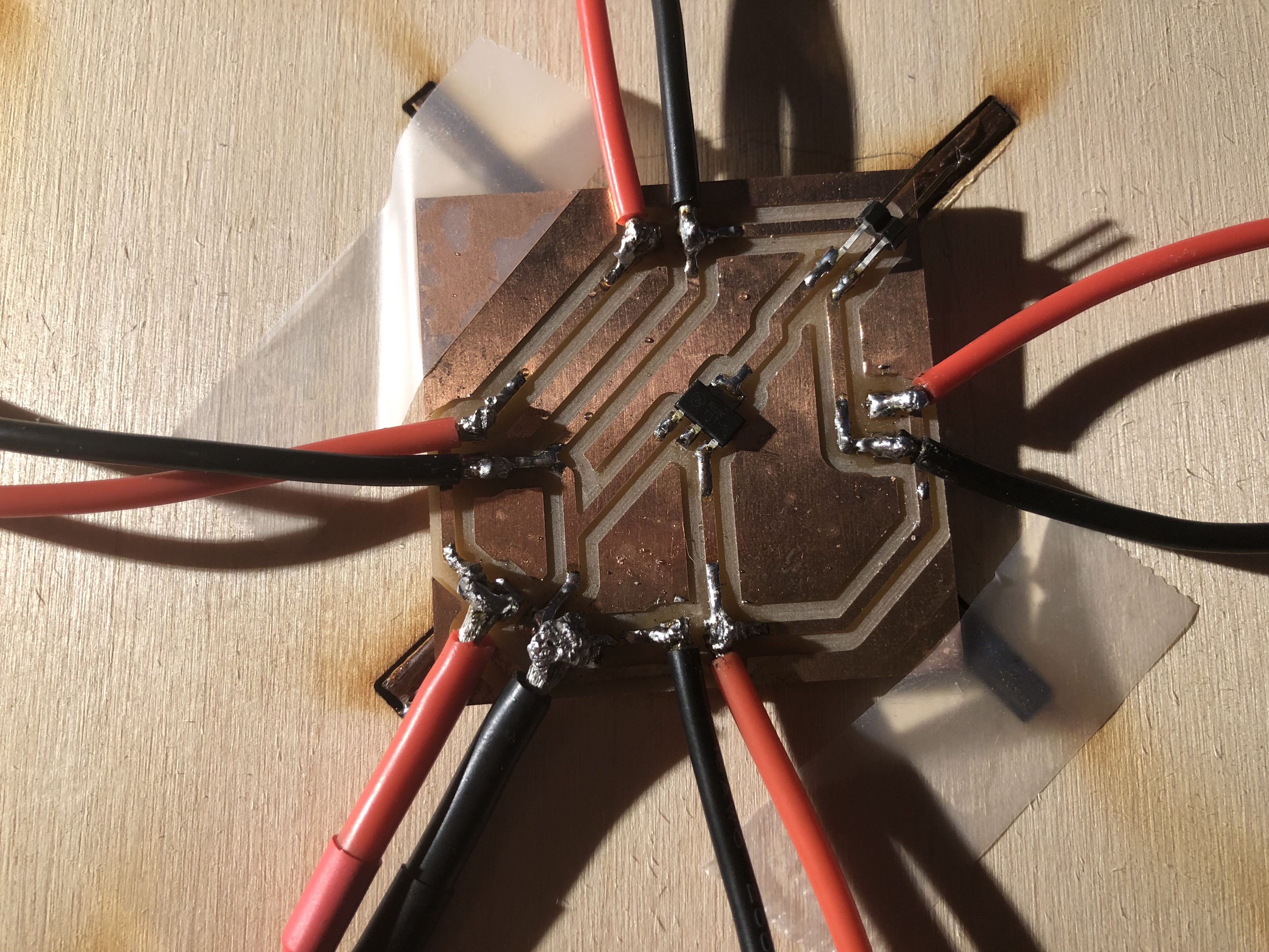
After milling out the board, I soldered on a 5V regulator and a 2 pin horizontal header to it according to my PCB diagram. Without soldering, I matched up the ESC end wires and the battery wires to their respective places, and determined that they indeed fit. Thus this demonstrated that the PDB indeed worked.
Propellers and Mounts
For the propeller design, I noticed when putting the props onto the motors that the prop holes were too big to fit the motors.
Thus I wanted to 3D print some pieces that would close the gap and make the props fit. I started in Fusion 360, where I used calliper measurements to design this rod looking piece.
After finishing the design, I went into PrusaSlicer, duplicated the piece 4 times, and sliced the stl design into a gcode file. Then I went into Octoprint, uploaded the file, and started the print.
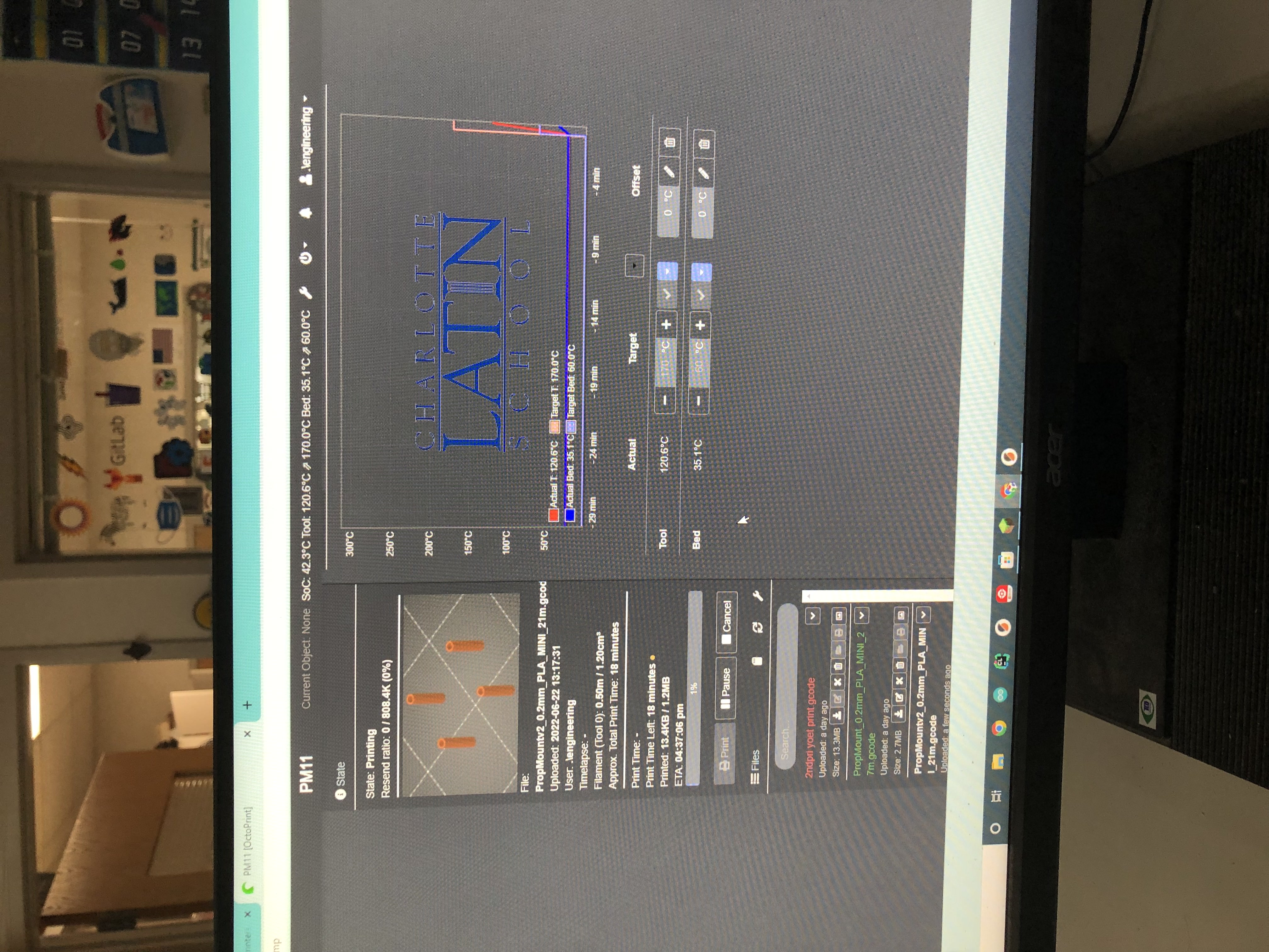
Here are the results of the print

Here’s how the prop mounts look when attached onto the props and the motors. As you can see they fit perfectly onto both things.
Transmitter and Receiver
To be able to transmit joystick inputs and receive them on my flight controller, I decided to buy a commercial transmitter and receiver as opposed to making one using the nRF24l01 module which I used during networking week. This was mainly because of the time constraints on the project which prevented me from making everything from scratch, and since quadcopters are so complex, I needed to focus more attention on the flight controller aspect. So, I decided to use the Radiolink T8FB 2.4 GHZ Transmitter in tandem with the Radiolink R8FM Micro Receiver, which outputs a PPM signal and is exactly what I needed. To verify that it was actually going to transmit and receive data, I wanted to run a PPM reader program and test the transmitter receiver with an Arduino.
First I loaded up the transmitter with 4 1.5V AA batteries.
![]()
Then, I looked for videos online of how to bind the transmitter and receiver I had, and I found this one specficially for the R8FM.
Following the video, I then powered up the receiver by hooking it’s 5V and GND to those respective pins on an Arduino Uno. The LED began flashing a bright purple, indicating that it received power. To bind the two together, I held the button marked ID SET on the side of the receiver, and waited until the LED stopped flashing, which indicated that it was properly bound.
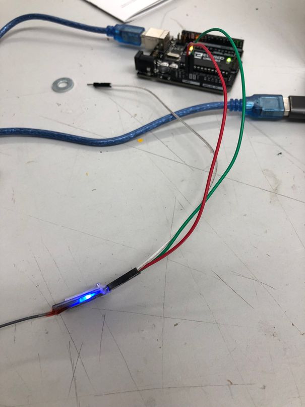
Finally, to switch the receiver from S-Bus (another form of data) to PPM (the data format I was using), I simply pressed the same button once again, turning the LED from purple (S-Bus) to red (PPM). Once both the transmitter and receiver were properly bound, I worked on finding a program which would decode the PPM output that the receiver gave to the Arduino and print the values of 4 channels, or the ones used by the joystick, which were the only ones I cared about. The idea was that if an Arduino could read what was being sent, then a satshakit flight controller would be able to as well.
During my research on PPM decoding programs I found two viable options at first. I decided to try both of them
For the first option, I used jumper wires to connect the PPM/S-Bus pin on the receiver to pin 2 of the Arduino. I first tried following the exact code, which worked in printing out some values, but only worked for the first six channels since the person who made the tutorial used a 6 channel receiver. Also, I noticed that the values weren’t changing correctly according to what I was doing with the transmitter and they were just randomly spasming out.
This was the code I followed at first
unsigned long int a,b,c;
int x[15],ch1[15],ch[7],i;
//specifing arrays and variables to store values

void setup() {
Serial.begin(9600);
  pinMode(2, INPUT_PULLUP);
  attachInterrupt(digitalPinToInterrupt(2), read_me, FALLING);
  // enabling interrupt at pin 2
}

void loop() {
read_rc();

Serial.print(ch[1]);Serial.print("\t");
Serial.print(ch[2]);Serial.print("\t");
Serial.print(ch[3]);Serial.print("\t");
Serial.print(ch[4]);Serial.print("\t");
Serial.print(ch[5]);Serial.print("\t");
Serial.print(ch[6]);Serial.print("\n");

delay(100);
}

void read_me()  {
 //this code reads value from RC reciever from PPM pin (Pin 2 or 3)
 //this code gives channel values from 0-1000 values
 //    -: ABHILASH :-    //
a=micros(); //store time value a when pin value falling
c=a-b;      //calculating time inbetween two peaks
b=a;        //
x[i]=c;     //storing 15 value in array
i=i+1;       if(i==15){for(int j=0;j<15;j++) {ch1[j]=x[j];}
             i=0;}}//copy store all values from temporary array another array after 15 reading
void read_rc(){
int i,j,k=0;
  for(k=14;k>-1;k--){if(ch1[k]>10000){j=k;}}  //detecting separation space 10000us in that another array
  for(i=1;i<=6;i++){ch[i]=(ch1[i+j]-1000);}}     //assign 6 channel values after separation space
Here is the first result which wasn’t quite what I was looking for.
After looking back at the tutorial and the comments, I noticed that I was having exactly the same issue as user jesse214 was having, where the code was only outputting “errant numbers that didn’t change”. I found out that he had solved the issue by changing the seperation delay from 10,000 to 5,000, and so I tried this solution as well. This was the modified code which worked in printing out 6 channels of data.
unsigned long int a,b,c;
int x[15],ch1[15],ch[7],i;
//specifing arrays and variables to store values

void setup() {
Serial.begin(9600);
  pinMode(2, INPUT_PULLUP);
  attachInterrupt(digitalPinToInterrupt(2), read_me, FALLING);
  // enabling interrupt at pin 2
}

void loop() {
read_rc();

Serial.print(ch[1]);Serial.print("\t");
Serial.print(ch[2]);Serial.print("\t");
Serial.print(ch[3]);Serial.print("\t");
Serial.print(ch[4]);Serial.print("\t");
Serial.print(ch[5]);Serial.print("\t");
Serial.print(ch[6]);Serial.print("\n");

delay(100);
}

void read_me()  {
 //this code reads value from RC reciever from PPM pin (Pin 2 or 3)
 //this code gives channel values from 0-1000 values
 //    -: ABHILASH :-    //
a=micros(); //store time value a when pin value falling
c=a-b;      //calculating time inbetween two peaks
b=a;        //
x[i]=c;     //storing 15 value in array
i=i+1;       if(i==15){for(int j=0;j<15;j++) {ch1[j]=x[j];}
             i=0;}}//copy store all values from temporary array another array after 15 reading
void read_rc(){
int i,j,k=0;
  for(k=14;k>-1;k--){if(ch1[k]>5000){j=k;}}  //detecting separation space 5000us in that another array
  for(i=1;i<=6;i++){ch[i]=(ch1[i+j]-1000);}}     //assign 6 channel values after separation space
Here is the result of test #2 which worked, but only for 6 channels and not 4 like I had wanted originally.
This result proved that PPM data was indeed being received, but still I wanted only 4 channels to be printed and not 6. I decided to give the PPM reader library a shot. After downloading and importing the PPM reader library, I initially didn’t know how to use it, but after looking at it’s github page, I found some example code which I modified. The original code looked like this, and was meant for 6 channels.
#include <PPMReader.h>
// #include <InterruptHandler.h>   <-- You may need this on some versions of Arduino

// Initialize a PPMReader on digital pin 3 with 6 expected channels.
int interruptPin = 3;
int channelAmount = 6;
PPMReader ppm(interruptPin, channelAmount);

void setup() {
    Serial.begin(9600);
}

void loop() {
    // Print latest valid values from all channels
    for (int channel = 1; channel <= channelAmount; ++channel) {
        unsigned long value = ppm.latestValidChannelValue(channel, 0);
        Serial.print(String(value) + " ");
    }
    Serial.println();
}
I wanted only 4 channels of data, so I modified the channelAmount from 6 to 4. The interruptPin was also changed from 3 to 2.
#include <PPMReader.h>
// #include <InterruptHandler.h>   <-- You may need this on some versions of Arduino

// Initialize a PPMReader on digital pin 3 with 6 expected channels.
int interruptPin = 2;
int channelAmount = 4;
PPMReader ppm(interruptPin, channelAmount);

void setup() {
    Serial.begin(9600);
}

void loop() {
    // Print latest valid values from all channels
    for (int channel = 1; channel <= channelAmount; ++channel) {
        unsigned long value = ppm.latestValidChannelValue(channel, 0);
        Serial.print(String(value) + " ");
    }
    Serial.println();
}
Here was the result of test #3, which finally worked exactly how I wanted it to. As you can see, the 4 channels of data from the joysticks are being printed and the value is changing in correspondence with the stick movement.
This proved that the transmitter and receiver subsystem worked.
Phase 3: Assembly and Integration
For the integration of the entire systme, I started with soldering the ESCs and Battery T connector onto the PDB I had made prior. I did this by taping down the PDB so it wouldn’t budge, then soldering each wire onto it’s respective pad.
After soldering everything, the next step was to calibrate each ESC with the correct throttle range. I did this by directly plugging in the receiver to each ESC like so.
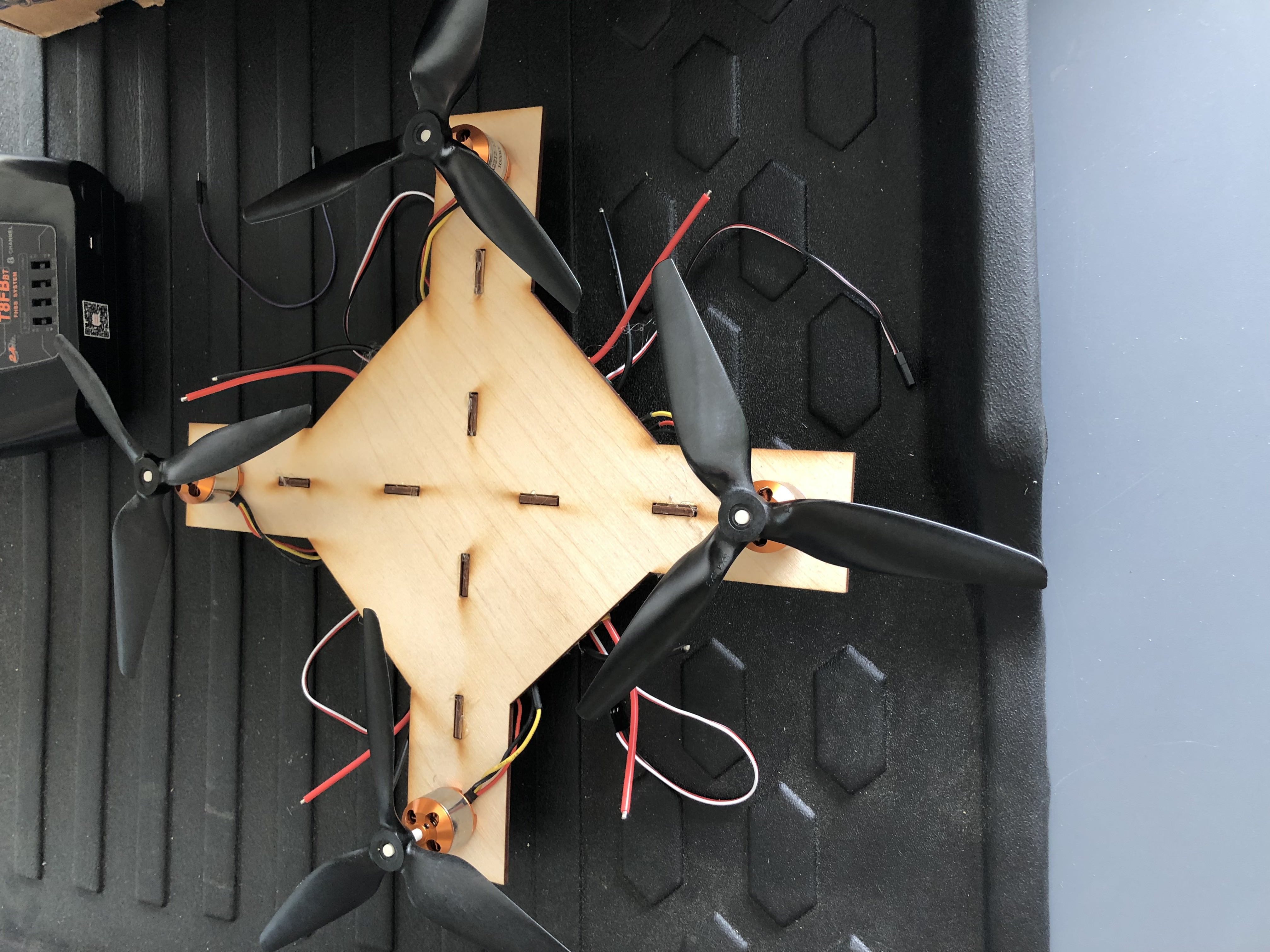
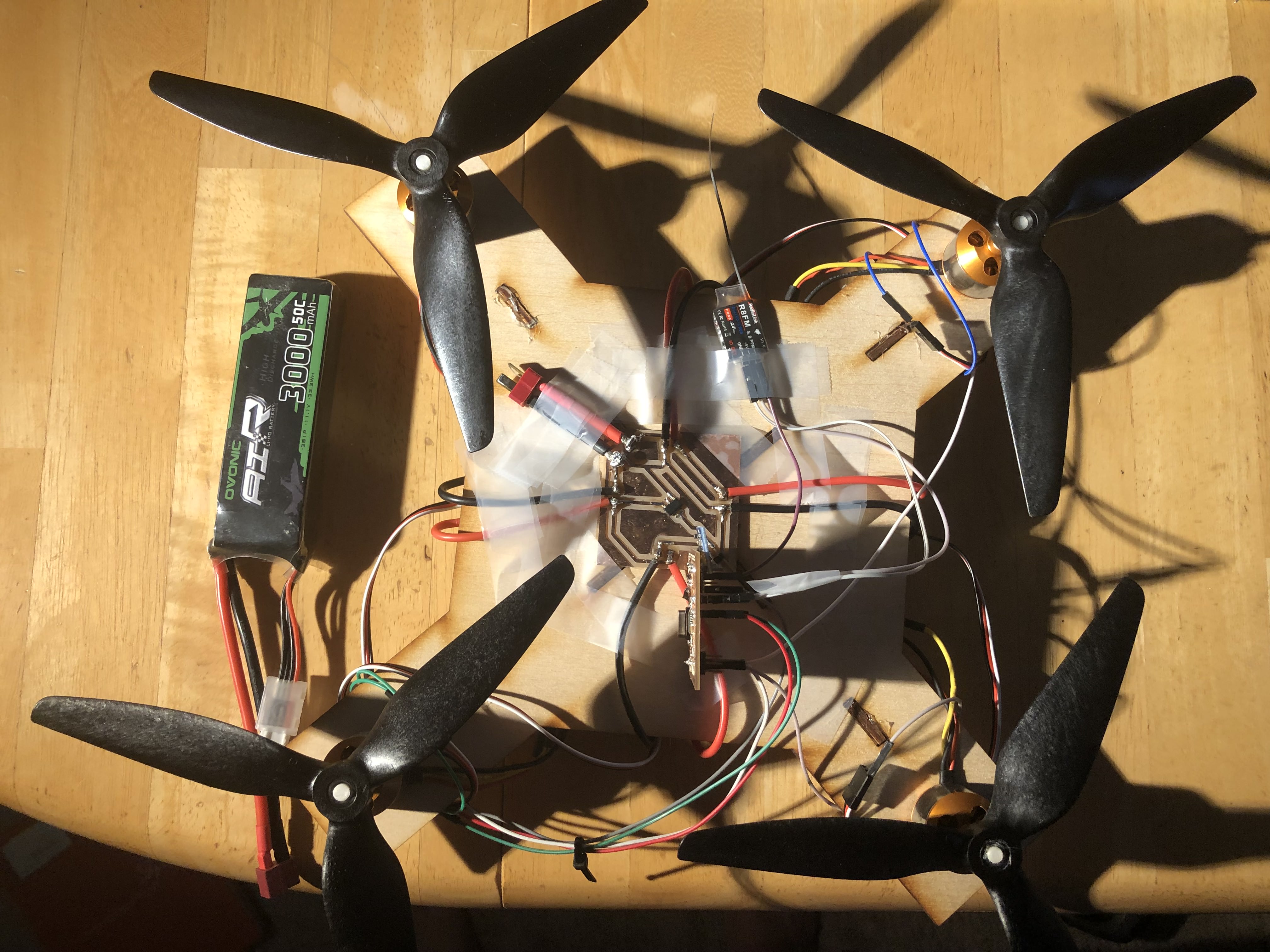
After calibrating each ESC, I plugged the wires of all electronic components into each other. This included connecting the PDB, flight controller, receiver, and transmitter together. Here was how it looked when set up.
Next I tried getting all four motors turning in unison, which I managed to do this after a few tests. As you can see, one of the motors was broken, so I worked to get that one replaced after this. Here is how that looked.
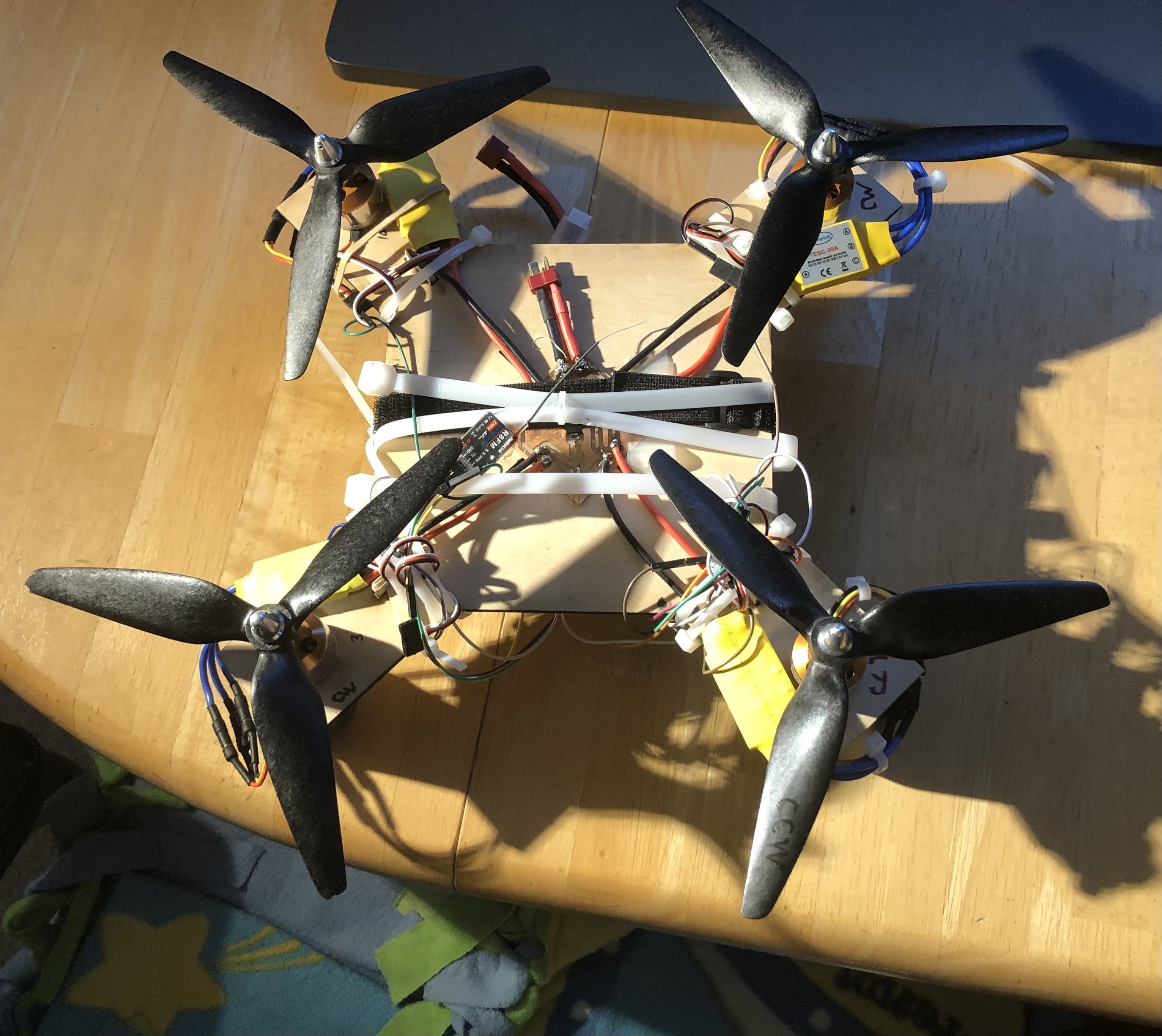
Here is how the quadcopter looked at this point without the new motor
Next I worked to actually get it to take off the ground. I also cleaned up the wire management of the quadcopter and organized it so that there weren’t loose wires hanging everywhere. Finally, I mounted the flight controller to the bottom of the frame since it had to be in a specific direction.
After much testing–going back and forth between the Multiwii IDE, the Arduino code, and the hardware–I was able to get the flight controller, transmitter, ppm receiver, escs, motors, and the frame all integrated together in a final product, although it was a difficult process due to the number of component parts which all had to work correctly for the quad to simply takeoff
Final Product
Here is how the final product looked, which was able to get off the ground.
Files
Quadcopter Frame(Corel Draw)
Transmitter and Receiver Test Code(Arduino)
Power Distribution Board F.Cu File(KiCAD)
Flight Controller Board F.Cu File(KiCAD)
Prop Mount Stl File(Fusion 360)
Multiwii Code(Arduino)
Questions Answered in Previous Weeks
What will it do?
My quadcopter will be able to achieve takeoff with its movements wirelessly being controlled by two external joysticks. Since the quadcopter portion itself is hard, the goal in Fab Academy for the first spiral is just to make it take flight, and I will expand on the project later on.
Who’s done what beforehand?
Obviously quadcopters are not a new thing and there are tons of prebuilt drones or drone kits you can buy online, of which here I have linked a few: Quad 1, Quad 2, Quad 3. However, these drones are all commercially made and thus cost hundreds and hundreds of dollars to buy. My goal is to be able to make a drone that is still able to fly but doesn’t cost as much.
Within Fab Academy, there are a few people I found who made a quadcopter, but it seems to be very rare. On top of that, within those people who tried to build one, I could only find three or so people who actually had documentation of it working. Here are a few people’s pages that I stumbled upon in my research.
The main one I will be referencing to create the project is Danielle’s page, since so far, he’s been the only one person whom I’ve found who has documented a successful quadcopter. Since he did an autonomous avoidance drone and I am doing an RC drone, I will have to make some modifications to what he did. Overall however, the frame, flight controller, and general things could be similar.
What did you design?
I incorporated both 2D and 3D designed elements into my final project. For the 3D design portion, I will use Fusion 360 to design mounts and cases for my PCBs which will be 3D printed. For the 2D design portion, I will use Corel Draw and Fusion 360 to design a custom frame, which will be laser cut out of wood. I will also use KiCAD to design a flight controller and power distribution boards, which will be milled from copper.
What materials and components were used? Where did they come from? How much did they cost?
Here is the full Bill of Materials which answers these three questions.
| Part | Quantity | Price | Place Found |
|---|---|---|---|
| 1000kV Brushless Motors w/ 30A ESC | 4 | $71.56 | Amazon |
| 4Pcs Carbon Fiber Propellers | 1 | $14.79 | Amazon |
| GY-521 MPU6050 6 Axis IMU | 1 | $6.29 | Amazon |
| RC Radio Transmitter and Receiver | 1 | $69.99 | Amazon |
| 3000 mAh 50C 11.1V LiPo Battery | 1 | $24.71 | Amazon |
| Total Cost | $187.34 |
To calculate the LiPo battery I wanted, I watched this helpful video by Painless360 explaining how to figure out which battery you need.
From this I figured out that the battery would need to provide 4 x 30A = 120A of current. Just to be safe, I wanted a battery that could provide at least 122A. Then the video explained that to find out a battery’s capable amperage, I would need to multiple the mAh value by the C rating. The final thing for figuring out batteries was that the video suggested that I get one with a higher C rating, since this would allow a physically smaller battery to be used while drawing the same current. I also read this article to understand much more about LiPo Batteries.
To actually figure out which battery to choose, I looked at this video.
What parts and systems were made?
Breaking down the quadcopter is a pretty straightforward process once I consider the different subsystems of the quadcopter: the flight controller and power distribution board, the radio transmitter and receiver, and the actual hardware including frame, props, and motor mounts. Of all these systems, the second subsystem will not be made custom, but the first and third system will be. After the first subsystem is made, I will network it with the transmitter and receiver, and then mount it all to combine it with the third system.
What processes were used?
Here is a table describing all of the processes I’m using and what they will be used for
| Process | Usage |
|---|---|
| Laser Cutting | Plywood Quadcopter Frame |
| Computer Aided Design | Frame Design and Mounts |
| Input Devices | Two Joysticks |
| Output Devices | Brushless DC Motors |
| Networking | Transmitter, Receiver, and Flight Controller Communication |
| Electronics Production & Design | Flight Controller and Power Board Design and Milling |
| 3D Printing | Mounts |
What questions were answered?
A potential question that still needs to be completely answered is whether I will be using the nRF24l01 tranceiver module to make a PPM transmitter and receiver, or whether I will use the store bought transmitter and receiver. Currently, I am leaning towards using store bought parts and this is likely what I will do.
How was it be evaluated?
My project should be evaluated on whether it is able to take off, which is ideally what the final product should do. Since my project is already predicted to cost less than normal commercial drones, if it works, then it proves itself as a cheaper alternative. After Fab Academy ends, I plan to try and replace the commerical transmitter and receiver with the nRF module, and see whether I can really make a quadcopter completely from scratch. Another thing I can do to expand after Fab Academy is possibly to try and add a camera. Whichever expansion route I take, it’s no doubt that what I’ve done in Fab Academy is only a first prototype.