8. Computer controlled machining
Assignment: Make (design+mill+assemble) something big
Editing in Fusion 360 and Laser Cutting
Cutting in Cardboard
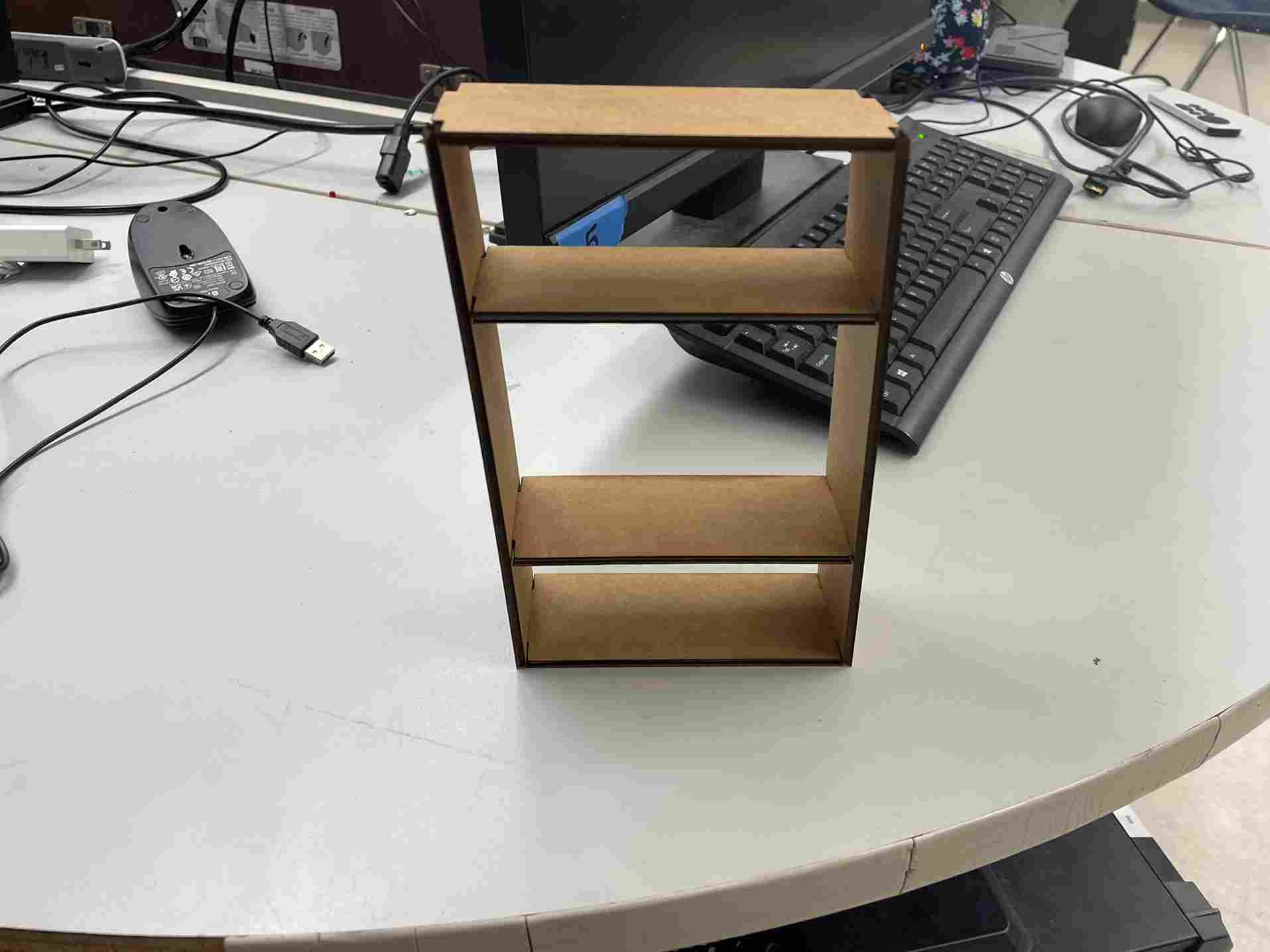
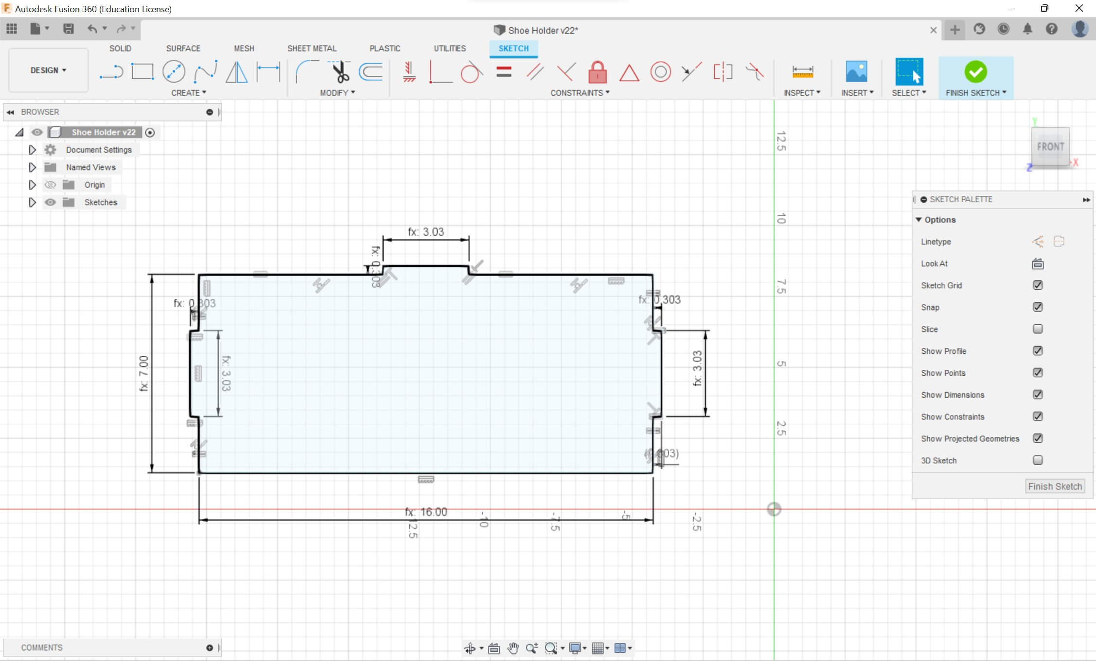
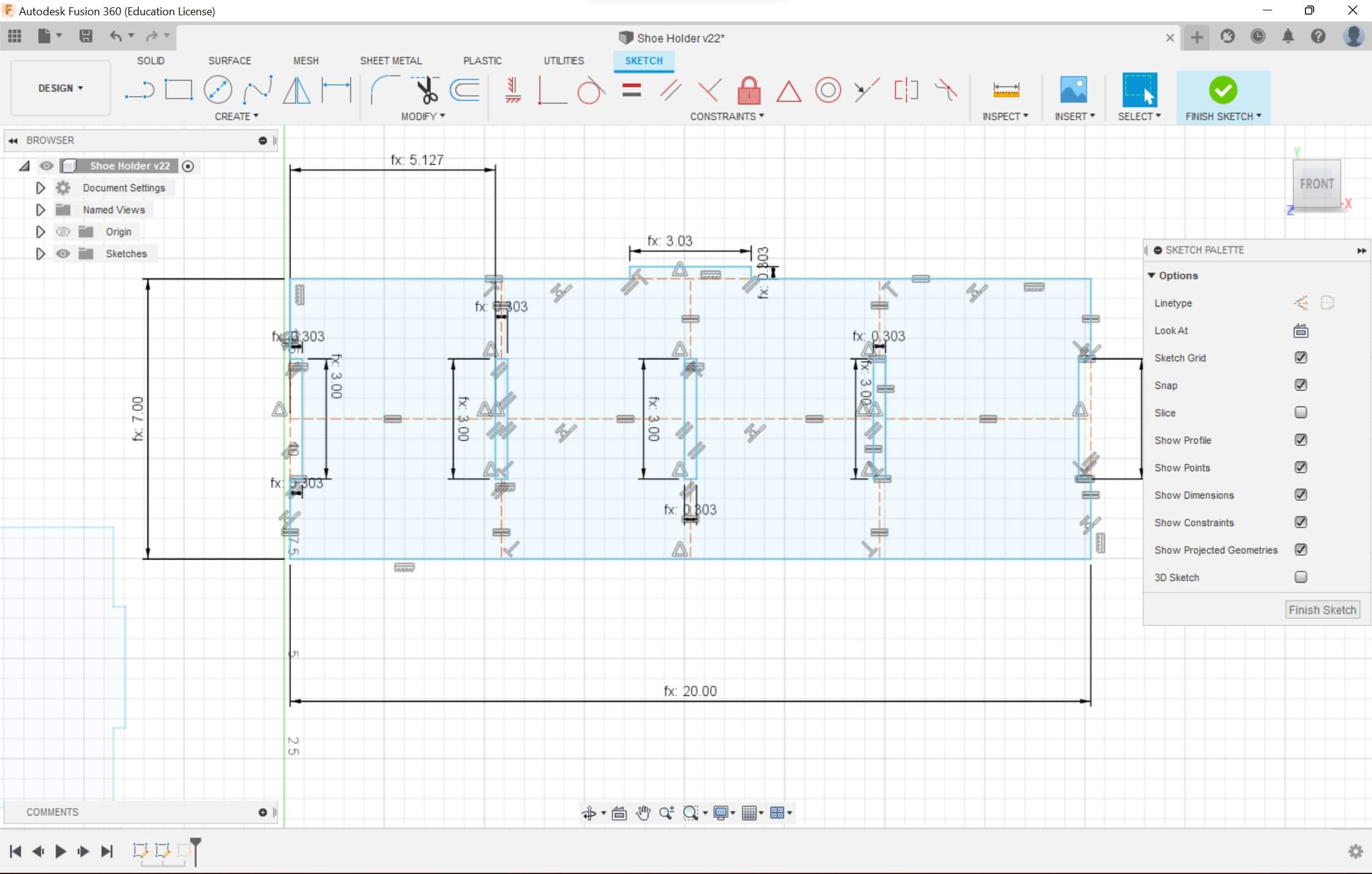
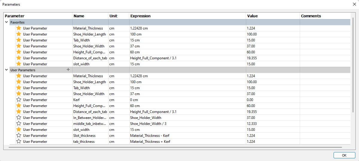
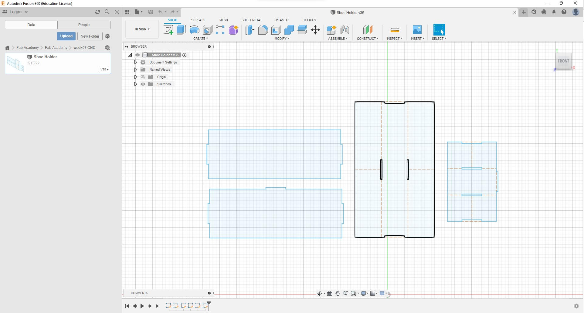
I knew that when designing the shoe rack, I would need at least two components: A vertical beam and the horizontal beam. My first task was to make something for the laser cutter to have a scale of what the object is going to look like. Using my earlier documentation of parametric designing, I created a multitude of parameters. I started with the laser kerf (which I wouldn’t have to include in the final cut in aspire), the material thickness (I was using cardboard), the height of the rack, the length of the rack (which would eventually have to span 1 meter), and finally the width of the rack. The next step was to create the tabs and the slots for the tabbed fit. I made the tab width the thickness of the material I would be using and the length an arbitrary number, I used 3 cm for the length. I decided I wanted to have 4 pads to place so I initially created two slots in the middle and slots extending to the outside of the design for the initial cardboard test. To make the distance between the edge of the vertical beam equal for both slots I created construction lines and added parametric functions to them. For example, the distance between the edge and the slot was a function of the height of the entire rack. So as the height would increase, the distance would increase by a certain amount. I loaded the file onto the printer and used cardboard.
Cutting in 1/8’’ wood.
The cardboard looked good but there was still some area for improvement. The cardboard design would slide from side to side because there was no back support. So, for the next design, I would include a back part, this would improve the look and address the back support problem. I also decided to add a third slot for more areas to put shoes in. I also encountered some problems regarding the kerf and the thickness of the tab concerning the slot. For the kerf, I realized that it would subtract material for the tabs, then add area to the slots because of the nature of the laser. To account for this, I had to add kerf to some lengths then subtract kerf to others for when the laser would cut across the lines. I also realized that I had made the tab length a little bit greater than the slot length so the wood would mesh perfectly. I realized I had to make the length greater by .002” after testing multiple cuts. To add the back design, I had to do two things; I had to add slots so it would mesh with the vertical beams then slots so it would mesh with the horizontal beams. I added the back piece with the tabs and slots, but I also had to add constraints with construction lines. I ended up taking the middle third slot out.
I printed this design and combined the pieces and they meshed extremely well
Preparing the Actual Cut
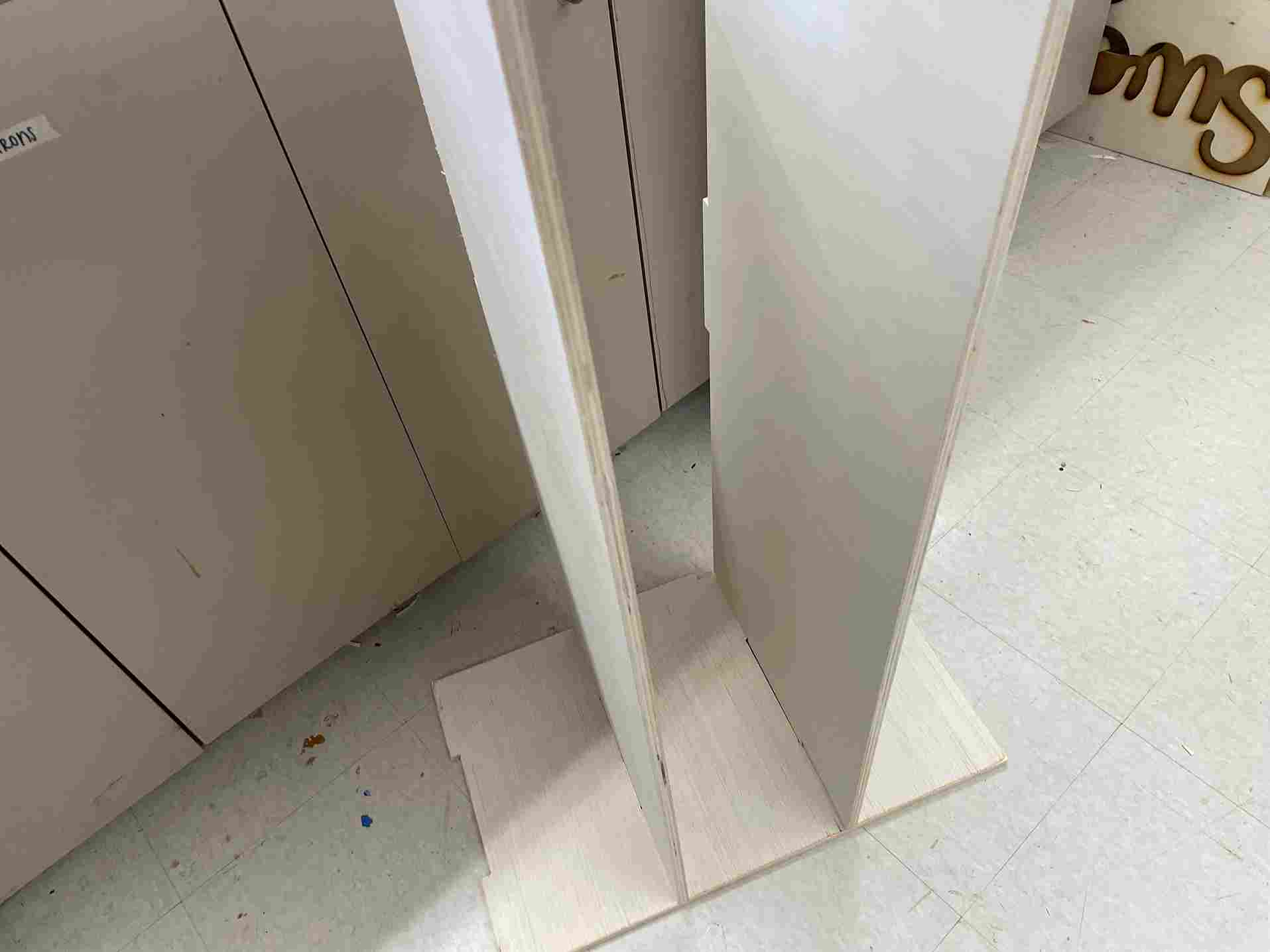
To measure the thickness for the tabs and slots I would use a meshing tool provided from the lab. The best value that my 1/2” wood would mesh with was .482”. For this step, I had to use a tape measure for both my shoe and for the height. Since I had the distance between each beam be a function of the height, I had to constantly edit the height along with the constant I was dividing by to have a value of 10 cm. while increasing the size of the components, I realized that some of my construction lines weren’t correctly scaling, so I had added more constraints to the design. After measuring all the dimensions of my shoes, I had the final design to scale. However, before uploading it into Aspire I realized that I had to add a different design for the horizontal beam. After I finished this, I uploaded the design into Aspire.
Editing In Aspire
First, I had to edit the job settings which included adding the bed’s length and width, I also had to include a thickness of .486” which I received by measuring my wood with calipers then taking the largest value. I made the design off the machine bed and the job setup was complete.
I saved the Fusion 360 file as a DXF, but I soon realized that a DXF file doesn’t save scaling values, so when putting the design into Aspire the scaling was completely off.
I decided to add a reference triangle that was the size of the job bed. I also realized that I could’ve uploaded the DXF into Corel Draw then save it as an SVG which would solve the problem. I uploaded the file with the rectangle reference. I scaled the design down so the rectangle was congruent with the scale of the job. That being 96 in by 48 in. I tried to add dog-bone fillets to the slots and tabs, but I experienced some issues. This was because my vectors weren’t combined. I click the button to combine them, but I still couldn’t add the fillets. I realized it was because the radius of the fillet wasn’t half of the tool bit. Since I was using a ¼” End Mill bit my radius, therefore, had to be .125”. Thanks to a suggestion by a fellow Fab Student Charlie Horvath I realized where I had to put the dog bones. I tried to calculate the tool path, but I was receiving an error. To fix this, I had to go back to Fusion 360 to clear up the paths. Charlie helped me again with this situation. By creating an offset plane then projecting the previous sketches onto the new plane I would be able to get rid of my construction lines and connect all the lines. I used the “P” button to project the sketches onto the new plane. I then deleted all the previous designs so I could upload this new design. I uploaded the file into Corel Draw and saved the file as an SVG. This would save the intended dimensions. I uploaded the file, and the scaling was perfect. I also could’ve used the join curves feature in Corel Draw to fix this issue.
I performed the same steps mentioned earlier. Combining the vectors then adding dog-bone fillets
The next step was to add tool paths for the specific vectors. I opened the toolpaths tab and clicked on Profile Toolpath to create my outline by doing,
- Selecting the outside/right cuts
- Tool: End Mill (1/4”)
- Edit Passes: To less than the size of my bit (.125”) mine was .1617” so 3 passes
- Add tabs
- Label the tool Path
- Calculate the path
For the inside slots it was the same, but the only difference was having the vector cut had to be Inside/Left.
Cutting on the Shopbot
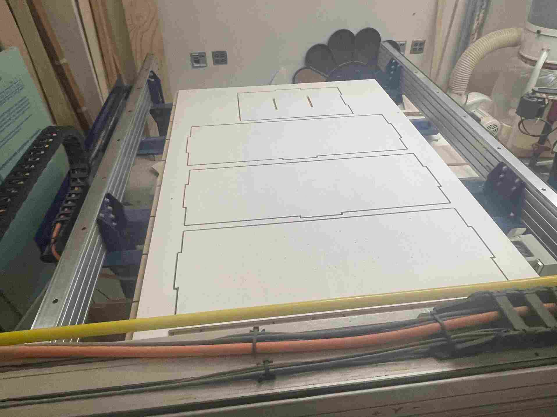
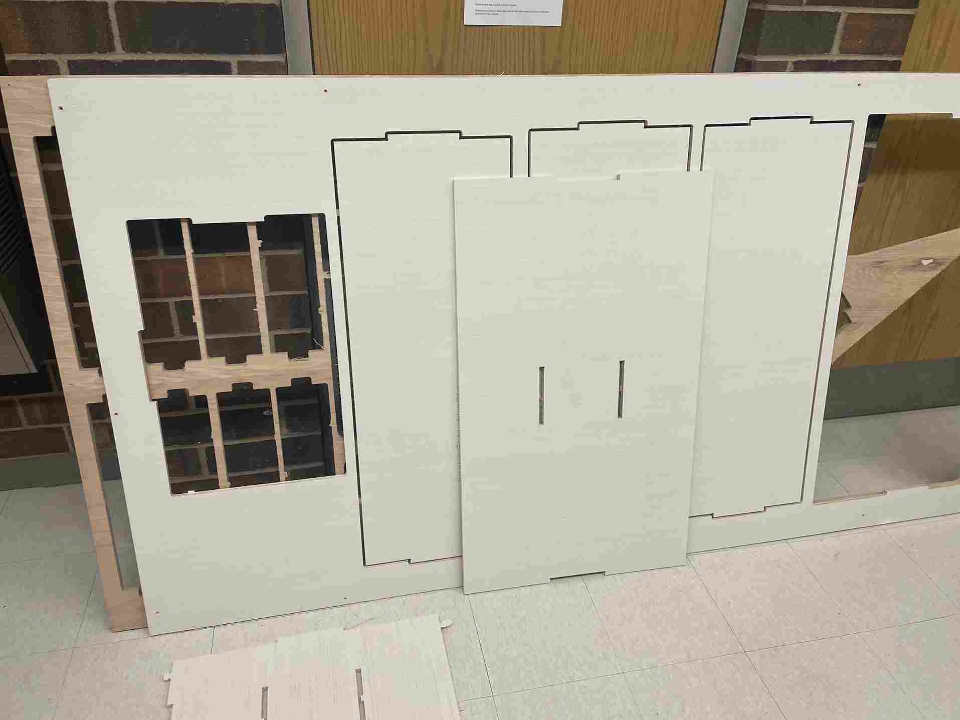
I saved the tool paths then saved the aspire file. However, I ran into some complications. One of the teachers in the lab loaded their wood onto the machine but soon realized that their file wasn’t ready. Since it would be a long process of removing her piece of wood and putting mine on, we decided to use her wood since there was only a variation of .002”. uploaded it into the computer connected to our lab’s Shopbot. I followed our labs workflow which included always having eye and ear protection on, zeroing the z-axis of the machine bed, zeroing the x and y-axis then offset by 3”, etc. At this point, I would normally drill in my piece of wood, but it was already prepared. I looked at the projected time for my cut and it was 3 hours. The teachers and I were deeply confused because my cut according to Mr. Dubick should only be 10-15 minutes. After troubleshooting, we realized that the feed rate was 40 in/min, instead of it usually being 250 in/min. Before cutting it, I realized that I wouldn’t have enough wood for my whole piece, so I had to edit the design in Aspire. I just deleted one of the slots on the vertical beam so that it would have only 3 slots for horizontal beams.
To test the cut, I ran a 3D offset and it looked good. I then activated the spindle then ran the cut for the inside slots. After the slots were finished, the power came unloose to the machine, so I had to rehome the zero. Our lab usually zeros off the machine bed but since the slots were already finished, I had zero off the wood surface then rehome the machine and re-offset the 0’s of the x and y axis. I then went into aspire and changed the cut, so it was off the material surface. After all the troubleshooting was finished, I ran the profile. After the first profile I had to stop the machine because when changing the feed rates my tabs were removed. I had to go back onto aspire then, edit the design so the vector that was already cut was deleted, then check that tabs were added to all the other cuts. After everything was fixed, my profile cut went through smoothly.
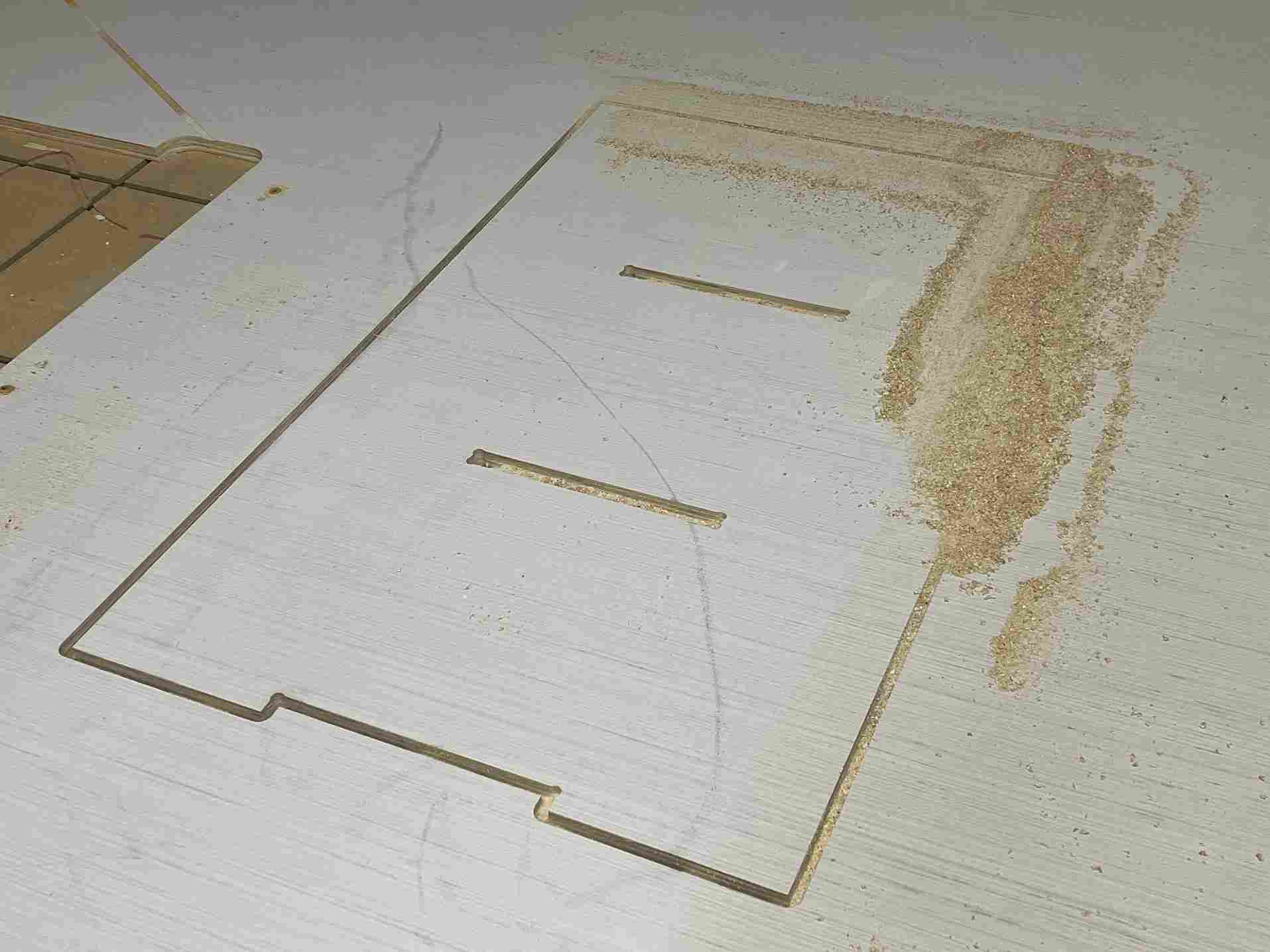
The next day I had to cut out the other vertical beam. This time I forgot to activate the lab’s ventilation. This left a lot of extra shavings.
After I cut this, I went looking for my other pieces, but it turns out that one of the teachers working the day previous took my components because we had similar designs, so I had to wait for them to bring the pieces back.
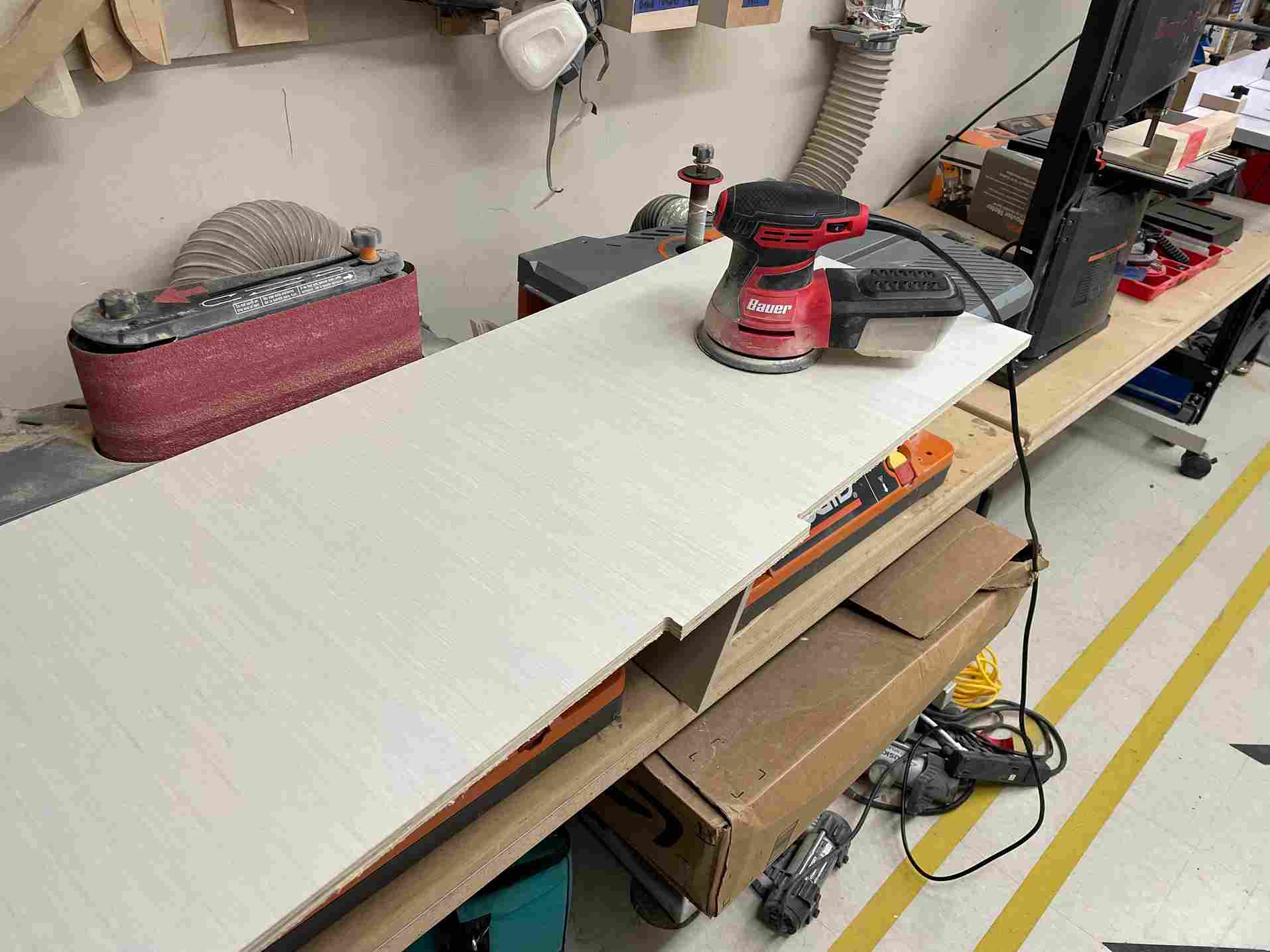
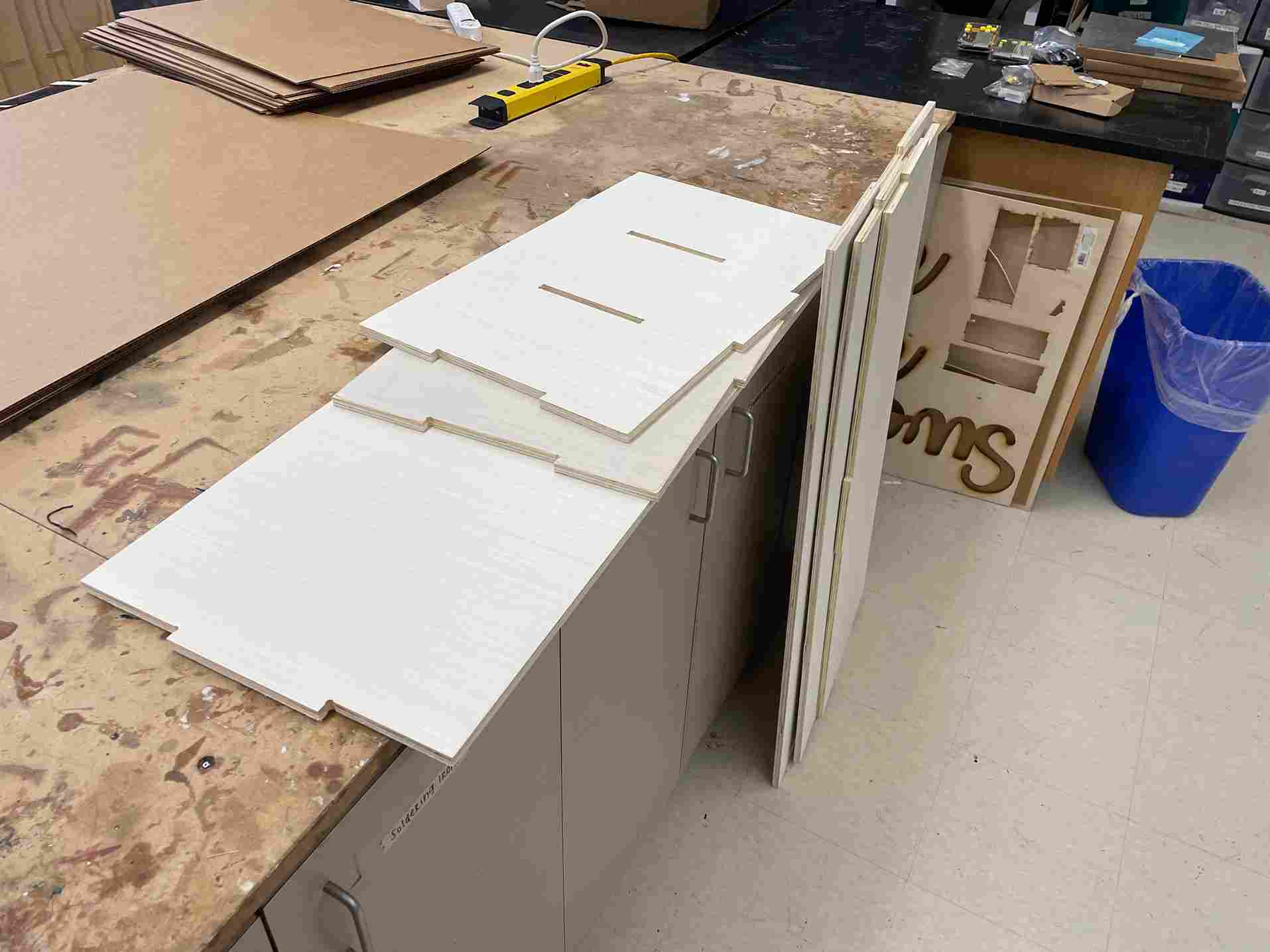
Sanding
I decided that I was going to sand down each piece because my family and myself would be touching the shoe rack and multiple occasions. I was used to the sanding process, so this process was simple.
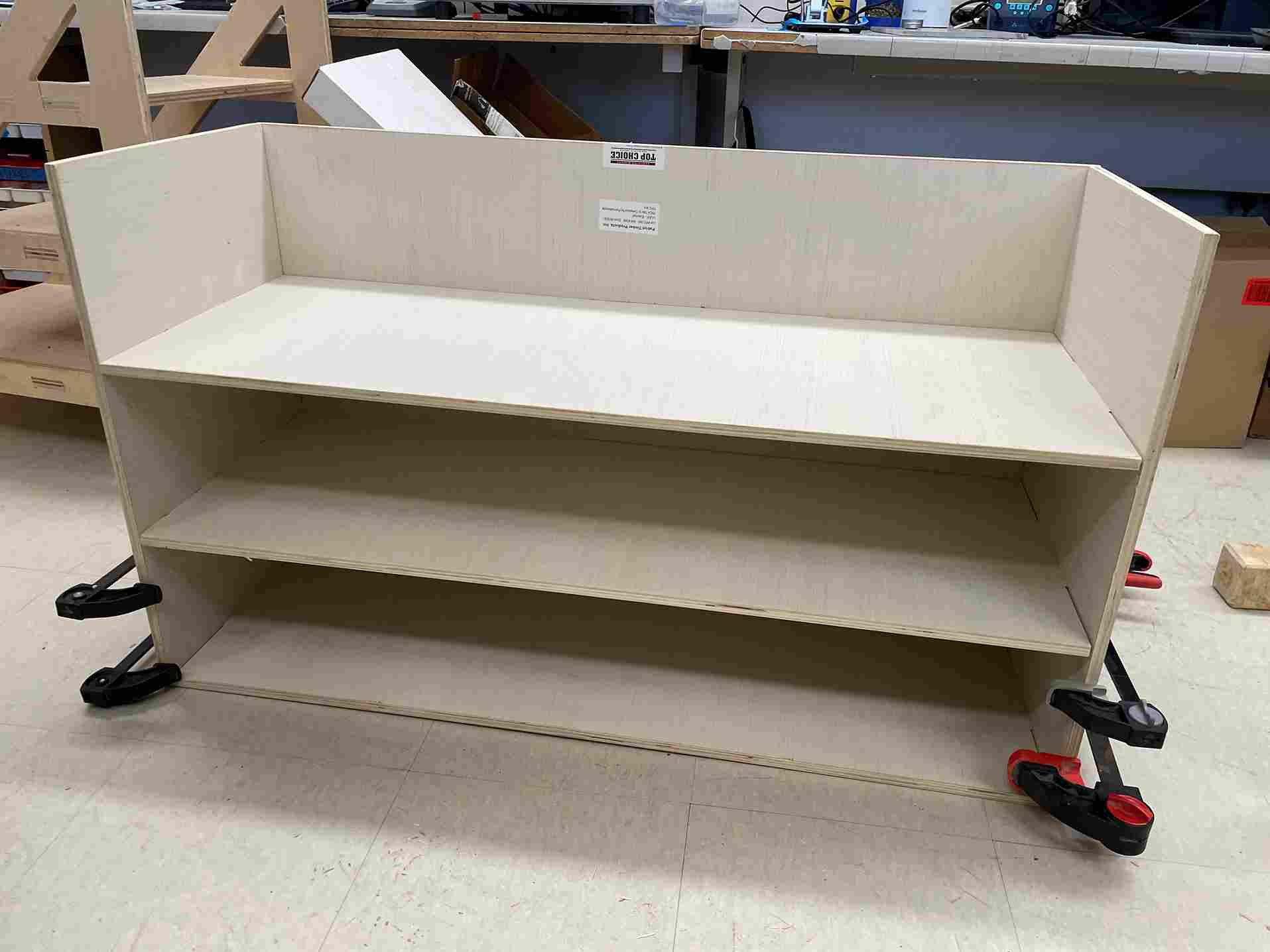
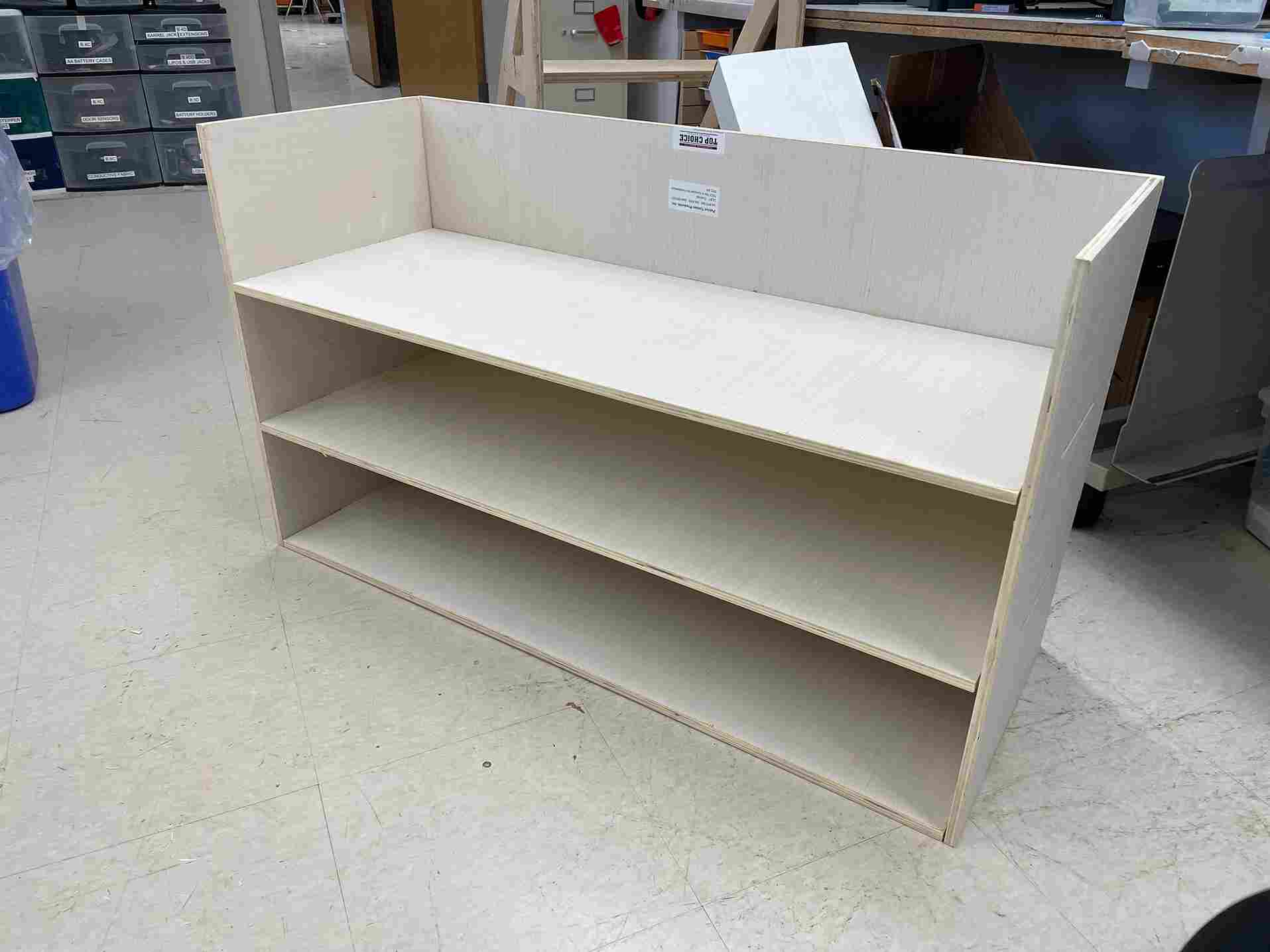
Assembly
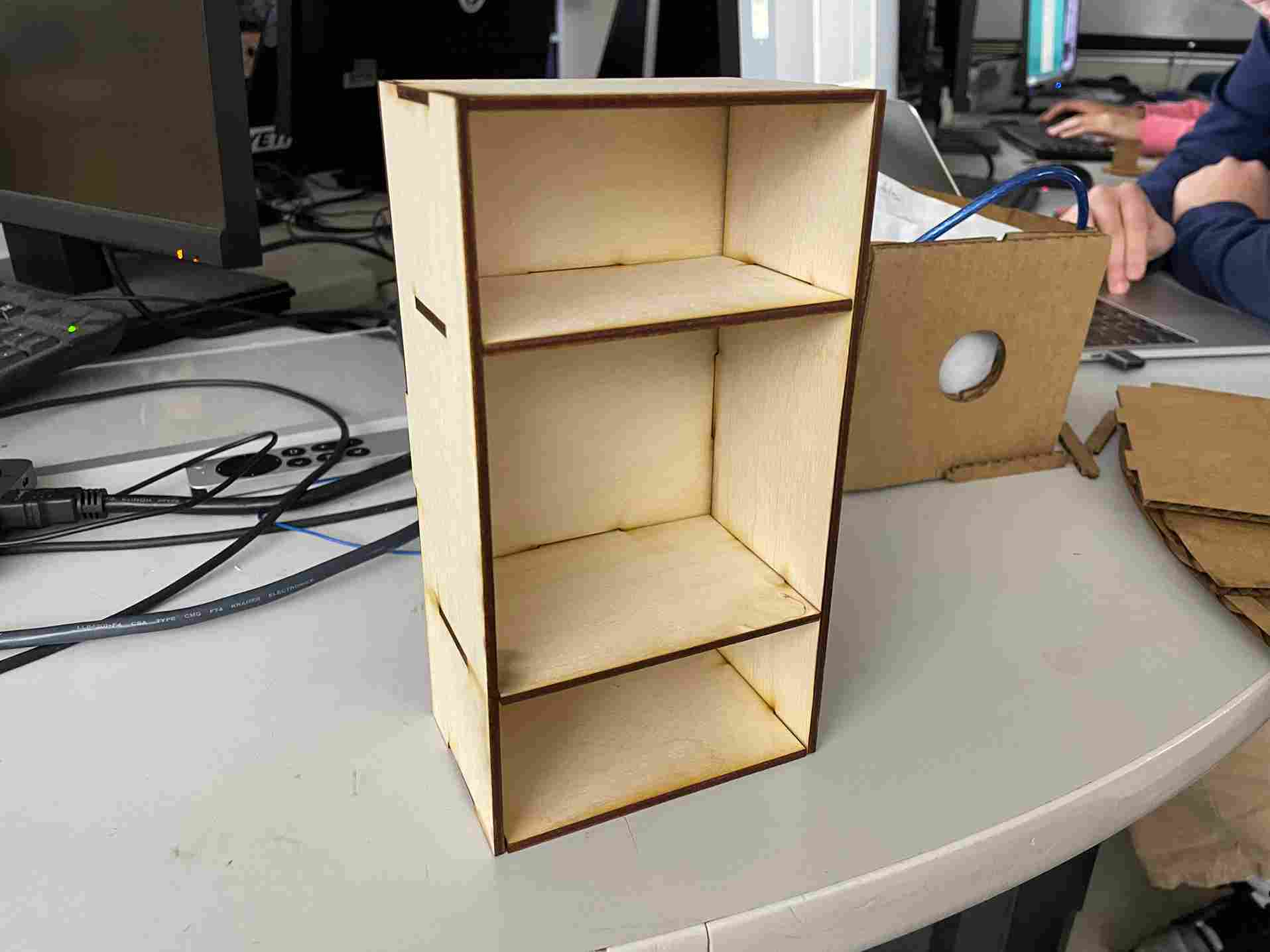
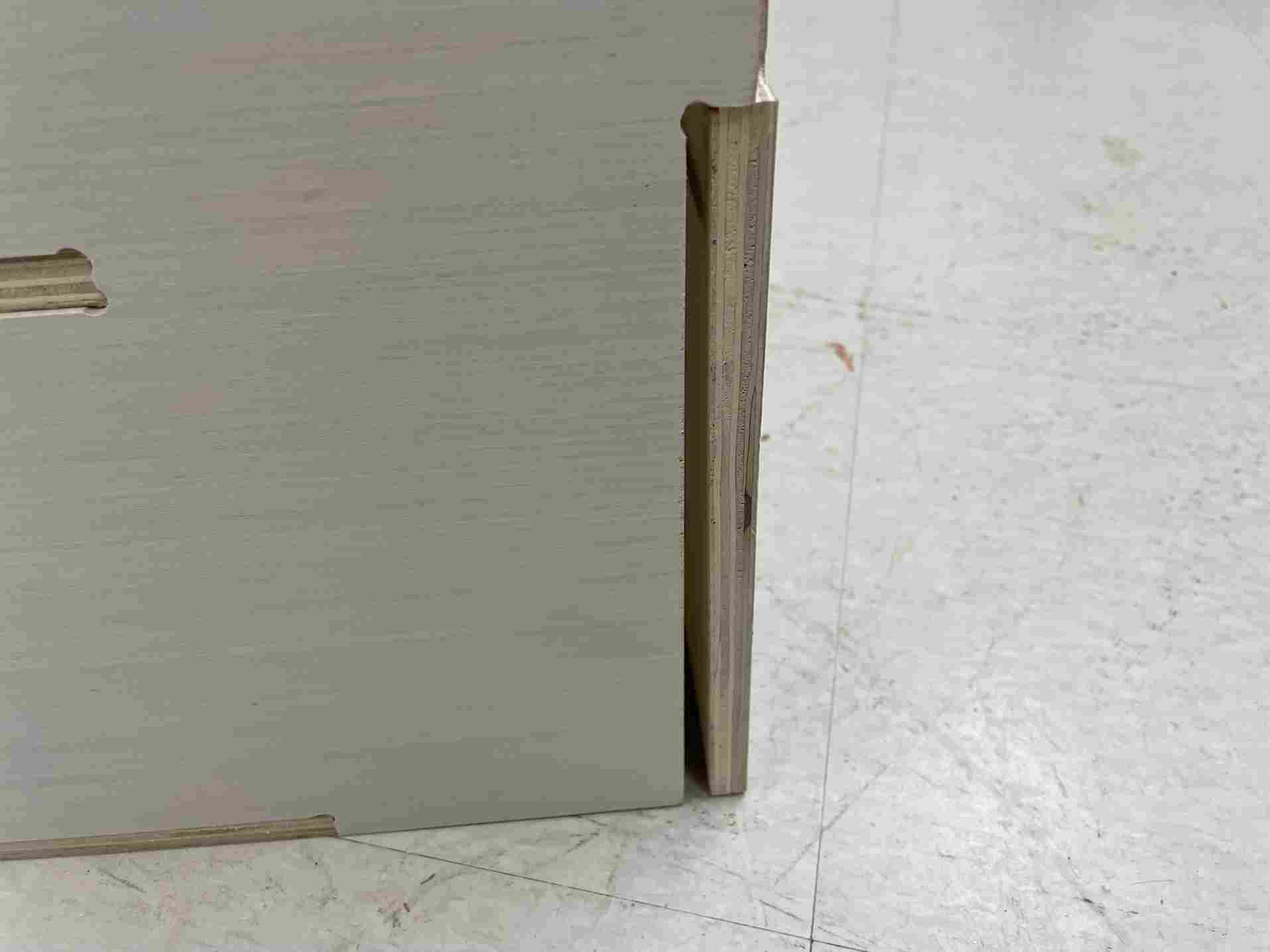
The final step was to assemble the components. Connecting the vertical and horizontal beams after sanding was easy, I just used a mallet to jam them in together. Since I had the outside tabs run as an outside/right tool path, the tabs were slightly bigger than the slots, once they meshed, the pieces weren’t moving. The most difficult part was adding the back piece. I received some help from a previous fab academy student Graham Smith in helping me file down some of the tabs and slots. After this I used the mallet, and my shoe rack was almost complete.
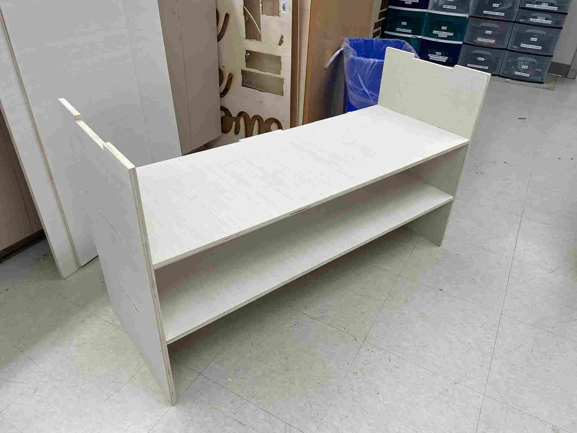
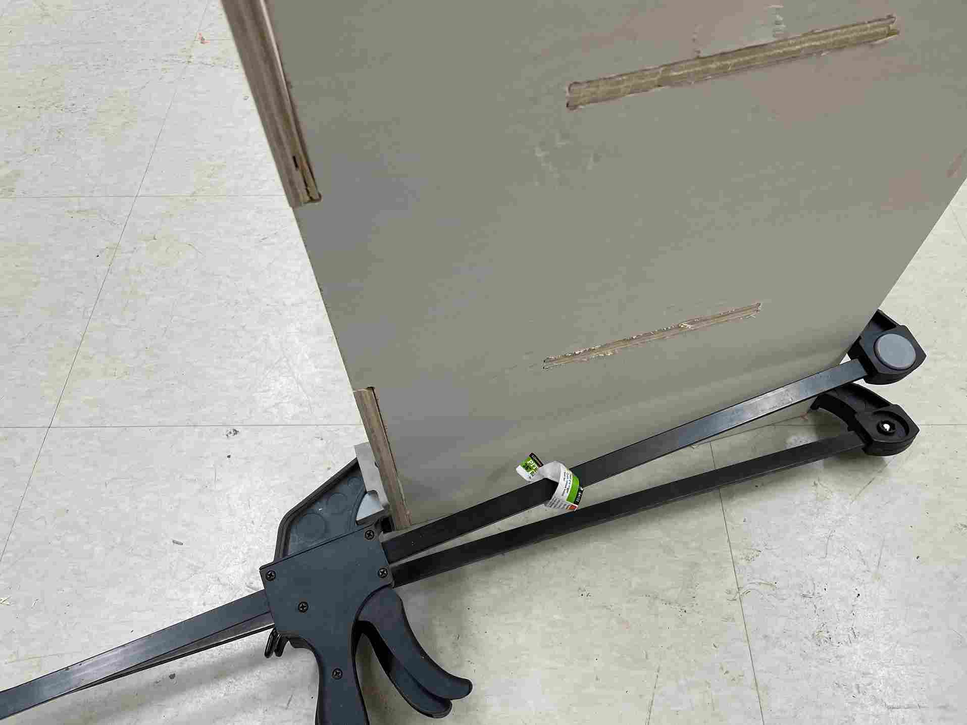
I noticed that the back piece was a little loose; I used wood glue and clamps to fix this problem. I waited for the glue to dry, and my shoe rack was done.
Problems I Ran Into
- Parametric not constrained so I had to incorporate construction lines
- Having to create functions for parameters
- Having to add and subtract kerf for the wood design in certain areas to create a better slot fit
- Changing the parameters to my real scale altered the shape of the components
- My curves weren’t joined so I couldn’t add dog-bone fillet
- I had to use a different piece of wood than intended
- The power disconnected after my first cut finished so I had re-align the z-axis from the material surface
- I had to change my feed rate so my 20-minute cut wouldn’t take 3 hours
- Changing the feed rate made all my tabs deleted from my design
- I didn’t have enough wood, so I had to use another piece for my vertical beam
- I didn’t turn on the vacuum so there were wood shavings in the
What I learned
I learned a lot about the Shopbot in our lab. But the most important thing I learned was how to safely operate the machines. In our lab’s workflow, the first thing people read is putting on eye and ear protection. Also, it is required that two people are in the room when the machine begins to cut something in case something disastrous happened. In terms of designing for the machine, I realized the importance of having dog or t-bone filets. I also learned that I didn’t need to account for kerf on the machine. Normally on the laser cutter, I make kerf a parameter. However, for the Shopbot, I didn’t need kerf because of the different tool path options.
Group Assignment
This week’s group assignment was to characterize the different aspects of the Shopbot in our lab. I specifically worked on the tool paths, and how making a tool path outside, on, or inside makes a difference in the size of the pocket/profile. I also worked on the runout of the machine. There are two types of runouts, axial and radial. Our documentation can be found on here.
Files
My files area locaded here