9. Embedded Programming
Assignment: Read the datasheet for your microcontroller, Use your programmer to program your board to do something
In previous weeks I’ve used my programmer and my new button blinky board to make an LED light up using a button or a delay function. During that time, I used the Arduino IDE and normal C ++ code. For this week, my instructor Mr. Dubick told us to directly manipulate the registers on microcontroller.
Preparing for Embedded Programming
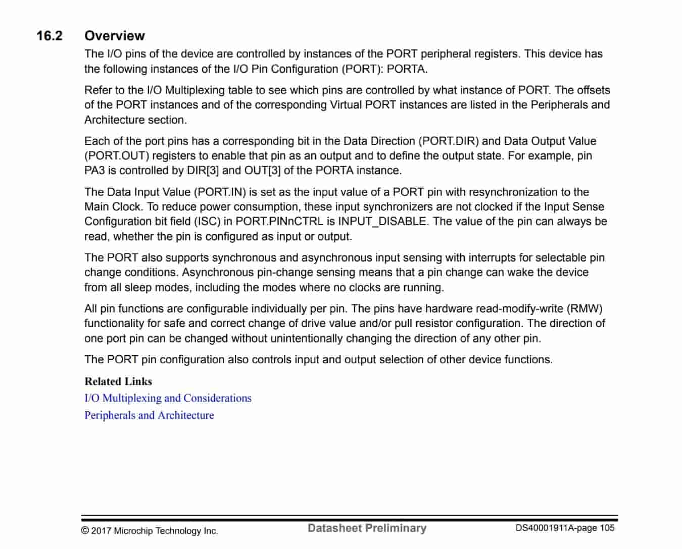
I thought I had a solid understanding of how and Arduino works, I realized after this week I did not. Mr. Dubick shared the videos below to help familiarize this kind of programming with us. These videos were very helpful for getting a solid foundation of an Arduino and the registers we can control in the microcontroller. When first trying to program my ATTIny412 in the Arduino IDE I realized that the port commands are completely different. For example, DDRB for an Arduino UNO would be the same thing as PORTA.DIR for the ATTiny412, which is something I learned from reading the datasheet.
Here are the videos that were helpful
Reading Datasheet of ATTiny412
After watching the videos mentioned earlier, I started reading the ATTiny 412 datasheet. I skimmed it and to be honest, it felt like I was reading a different language. I was familiar with some of the concepts such as different register storage and the pin configuration (which is what I would use to program my board). A lot of my understanding of the datasheet came from the videos but also just slowly reading carefully at some moments. It is easy to skim through a lot of the information, especially the info that is important to the project. I would end up reading the same paragraphs on pull up resistors and outputs 6-7 times before I finally understood it.
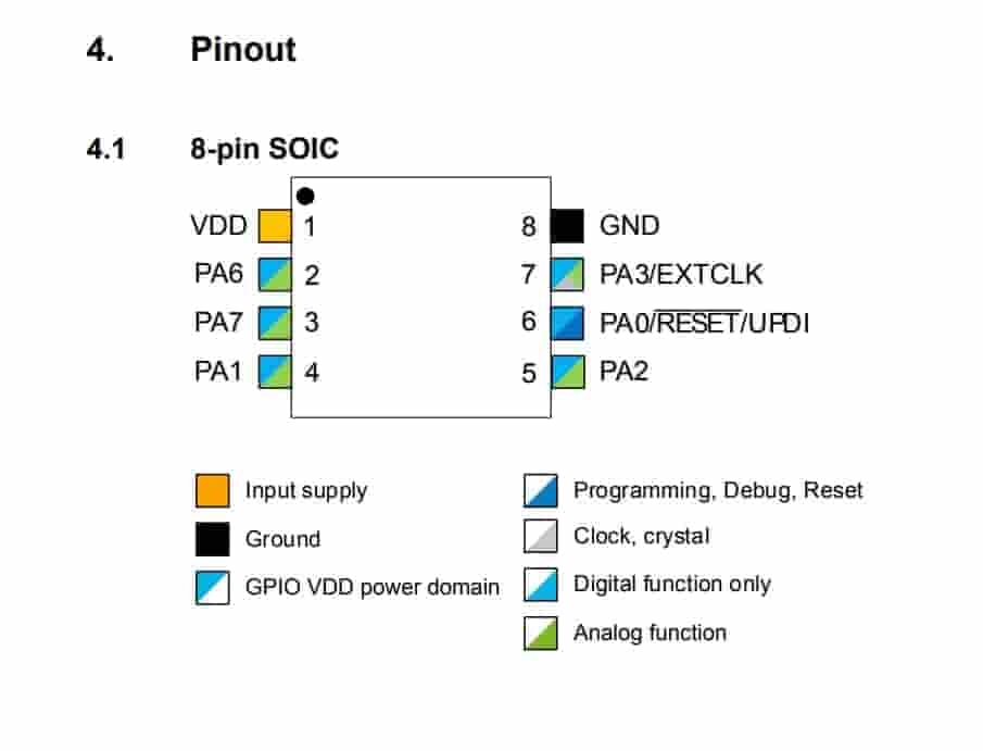
The information I found most important was the pinout image, the detailed pin image, and finally the information of configuring a pin to be an output, input, etc. Most of the information I used was located in section 16.
Platform IO
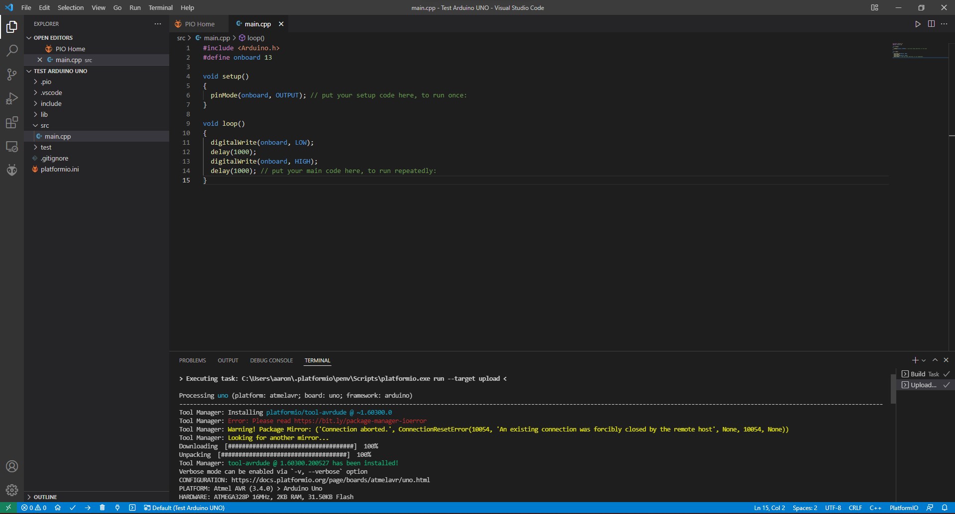
After watching Dr. Gerstenfeld’s lecture I wanted to try Platform IO. After watching the video below and looking at Drew Griggs’s and Teddy Warner’s documentation (two FAB students from the previous year) I realized that I could embed this IDE into VSCode. The instillation process was simple after watching this video and I was ready to use my programmer. I first used an Arduino UNO to test the built in LED. Configuring a board on Platform IO in my opinion was much easier than Arduino IDE for a couple of reasons.
- Platform IO Auto detects my COMS ports
- Platform IO allows you to just type the board into the software and will download the necessary material to program it
- Having Platform IO integrated into VSCode (one of the best text editors) after watching a simple tutorial video, makes coding much easier.
I was able to program the LED on the Arduino UNO with ease and the next step was to use my programmer to code the ATTiny412 chip on my binky board. I typed the microcontroller into the software Platform IO did the rest. I used a simple blinky code to test it.
However, I ran into a major issue. When I tried to program the ATTiny412 with my SAMD11C programmer (which I made during PCB Production week), it would reset my programmer. This meant I had to reconfigure my programmer to be a programmer. I received this error right before my board was reset
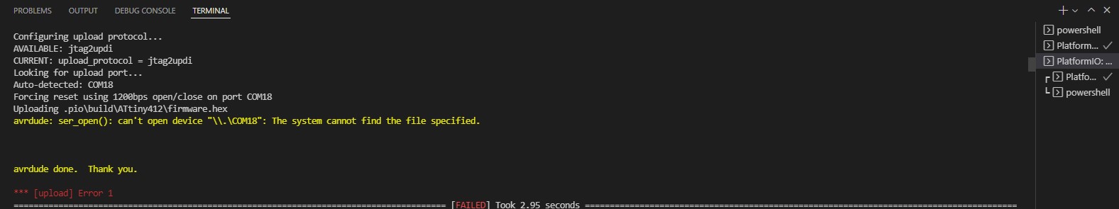
I thought it was something simple like the COMS port was disconnected or a wire was disconnected. I used my Atmel ICE made from a previous week, to reprogram the SAMD11C. I double checked everything and ran the code but still received the same error and my board reset again. I scoured the internet for a reason as to why this was happening to no eval. I tried about 3 more times to program the ATTiny412, but it never worked. Keep in mind that reprogramming the SAMD11C to act as a programmer is not a simple process; it takes about 5 minutes to reconfigure it, just to get back to where I was previously. I was confused because the Arduino IDE was able to use my programmer easily, but not Platform IO. I gave up on trying to use my programmer and used my Arduino as a UPDI programmer. I used my earlier documentation to upload the jtagupdi bootloader. After this process was complete, I plugged in the ATTiny412 to the Arduino UNO and the code worked using Platform IO. Even after all of this, I still enjoyed using Platform IO and I will probably continue to use this.
Embedded Programming
Learning Binary and Decimal Coding
My instructior Tom Dubick presented this slide show on bare metal programming. These two images were most helpful
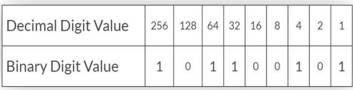
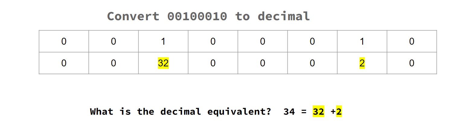
The presentation is in terms of an arduino but the concept is the same for an ATTiny412. Each pin is connected to a register which can be directly controlled using binary or decimal coding. In the top example PORTB on the arduino has 8 bits (or 1 byte). The pins can be toggled to either 1 or 0. In this case, 1 means a high signal while a 0 means a low signal. the port number corresponds to the decimal value. So the internal LED pin on an arduino (pin 13) is located at port register B bit 5 or PB5 or PORTB bit 5. to toggle this on, I would have to write a line of code to set this bit to a value of 1. I have two options that equate to the same thing. The first option is to directly type binary by saying
PORTB = B0010000
This means that for PORTB, bit 5 is toggled on. The decimal equivilant of bit 5 is 32, so I could replace this line with a simpler one being.
PORTB = 32
To control more bits I could either add a zero using binary or add the decimal equivilant of all the pins to turn them on.
Configuring Pins
To make this process easier for me I would use my code from my previous documentation and individually change each function. For example I would look at the digitalWrite(ledpin, HIGH) and only change this into PORTA.OUT = 128. 128 is the decimal number of bit 7, so writing this equates to a 1 for that bit which turns on bit 7 of PORTA. it would be the same as typing PORTA.OUT = B10000000". Before using the button, I simply wanted to make the LED blinky using embedded programming.
Blinking Code
As I mentioned earlier, I thought that setting a pin as an output would be the same thing as and Arduino UNO, it was not. I recevied this error while uploading.
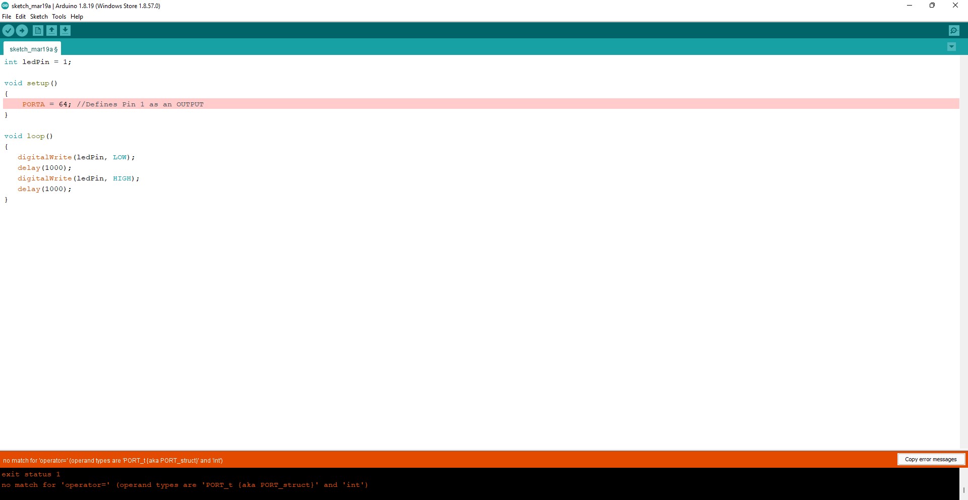
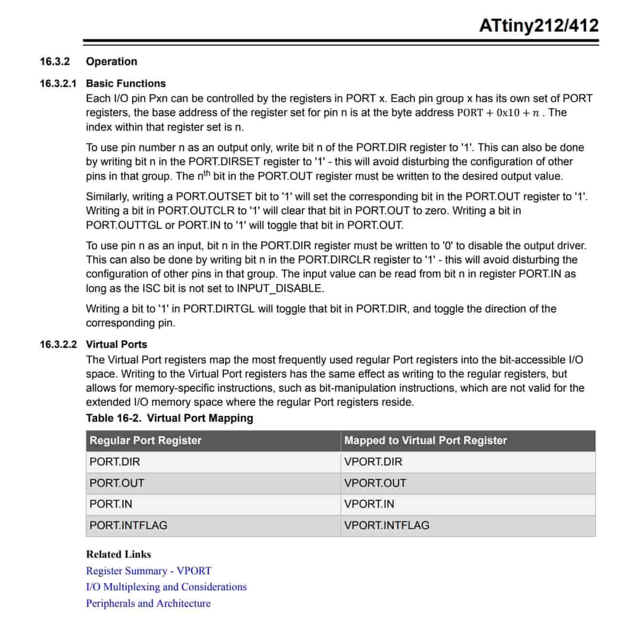
After multiple hours of rereading the datasheet, I realized that the command was PORT.DIR with a “1” equaling an output and conversely a “0” would equal and Input. I would use PORT.DIRSET to configure an output and PORT.DIRCLR to configure an input. The datasheet said that these commands were useful if we wanted to directly configure a pin without affecting the others. I thought that this would be the best option and continued with it. I would soon realize that it would be hard to read inputs later through the process. Regardless, until my final piece of code I would use these commands. The blinky code I used for my board is below.
BLINKY code
void setup()
    {
    PORTA.DIRSET = 128;
    }
void loop()
    {
  PORTA.OUTSET = 128;
  delay(500);
  PORTA.OUTCLR = 128;
  delay(500);
    }
Activating Pullup Resistor
The next step was to add a button and for that I used the code from week 7 PCB Design and directly configure this. Configuring the digitalWrite and the output were simple. A problem that I ran into was trying to activate the pullup resistor because when it wasn’t turned on the LED would be inconsistent when trying to turn it on.
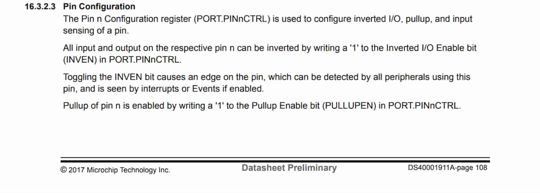
I tried multiple combinations of different commands (I think some of them weren’t even meant for an ATTiny412) and nothing worked. The datasheet told me that the command PORTA.PIN3CTRL was used to activate pullup, but what I eventually figured out with assistance from Drew Griggs that the pull up resistor was a bitmask. I thought that just simply typing out PORTA.PIN3CTRL would activate it, but I had to use a bitmask or command to make the input pin register as a “1” for 5V. I did this by typing
PORTA.PIN3CTRL = PORTA.PIN3CTRL | PORT_PULLUPEN_bm;.
After doing this I didn’t have any problems with the pull up resistor
Here is my code for this part of the process
int ledPin = 1;

void setup()
{
    PORTA.DIRSET = 128; //Sets pin 1 as an output while not affecting the other pins
    PORTA.DIRCLR = 8; //Sets pin 4 as an input while not affecting the other pins
    PORTA.PIN3CTRL = PORTA.PIN3CTRL | PORT_PULLUPEN_bm; //Activates the PUllUP resistor for PA3
}

void loop()
{
    if (digitalRead(4) == HIGH) // Button Isn't Pushed
    {
       PORTA.OUTSET = 128; // LED will stay off
    }
    else
    {
        PORTA.OUTCLR = 128; // LED turns on
    }
}
Changing All of My Code
The final step was to add the digitalRead. Up till this point I was still using that function to test the functionality of my board. Again, I spent hours trying to figure out how to find a way to incorporate the pin read. I sometimes the LED would stay on or stay off regardless of the button input. I thought I was close to figuring it out, but I never did. The following day, I consulted with some fellow fab students, Nhidie Dhiman and Alaric Pan, I realized that because I was using PORTA.DIRSET and PORTA.DIRCTRL, it would be harder to incorporate the input signal. Ms. Dhiman referenced youtuber Mitch Davis to help me with this problem. Ironically, this was the same person that created one of the first videos I watched at the beginning of the week. The YouTube video mentioned earlier was the first video of an eight-part series in microcontrollers. These were helpful, and I highly recommend watching them. The most helpful video is below.
Here is his entire playlist on using Bare-metal programming. I recommend watching the all 9 videos because he does such a great job of explaining and breaking down each aspect of his code.
After watching the video, I went back to VSCode with a new understanding of what I was doing and exactly what I had to do next. I got back to the point where I was previously, where I had everything except for the digitalRead. At this point I had replaced the “SET” commands with basic commands. Which is shown here
//Button is PA3
//LED is PA7

int ledPin = 1;

void setup()
{
    PORTA_DIR = B10000000;  // Defines OUTPUT as PA7 and INPUT as PA3
    PORTA.PIN3CTRL |= PORT_PULLUPEN_bm; // Makes the button pin read as HIGH if button isn't pushed
    PORTA.OUT = B10000000;
}

void loop()
{
    If (digitalRead(4) == HIGH) // Button Is Pushed
    {
       PORTA.OUT &= ~(1 << 7); // LED will stay on using B01111111
    }
    else
    {
        PORTA.OUT |= (1 << 7); // LED turns off
    }
}
- PORT.DIR: Sets the output and input pins (0 being input, 1 being output)
- PORT_OUT: Sets the state of the output pin (5v or 0v)
- PORTA.PIN3CTRL |= PORT_PULLUPEN_bm : Activates the pullup resistor in PINnCTRL
Before I set each port individually using PORTA.OUTSET and PORTA.OUTCLR. This time around I used bit masking to change the individual bit value for PORTA.OUT. After watching the videos, I had more of a conceptual understanding of all of this, along with spending hours researching and reading the datasheet. This change would be imperative in order to configure the input pin.
Reading the Button
My final task was to incorporate the button. I read in the data sheet that the command I would need would be a PORTA.IN which configures the pin to read incoming data. I knew I needed to add more and figure out that I had to use bit masking so the value that would be able to change between a 0 and 1 when the input value was changing. Initially I thought I had to use an or bitwise operation but running this cause my led to only stay. This was because I was downshifting a 1 so using an or operation would cause the value to always stay at 1. I changed the operation to an and bitwise operation and my board WORKED (but not the way I wanted it to). The LED would turn off when the button was pushed. I knew that I could simply switch the statements, but I wanted to challenge myself and only change the if statement. Thanks to Alaric Pan I could simply use a “not” or “!” to inverse my if statement. I added this and my board worked. My final code is below
//Button is PA3
//LED is PA7

int ledPin = 1;

void setup()
{
    PORTA_DIR = B10000000;  // Defines OUTPUT as PA7 and INPUT as PA3
    PORTA.PIN3CTRL |= PORT_PULLUPEN_bm; // Makes the button pin read as HIGH if button isn't pushed
    PORTA.OUT = B10000000;
    PORTA.IN = B00001000;
}

void loop()
{
    if (!(PORTA.IN &= (1 <<3))) // Button Is Pushed
    {
       PORTA.OUT &= ~(1 << 7); // LED will stay on B01111111
    }
    else
    {
        PORTA.OUT |= (1 << 7); // LED turns off
    }
}
Using Memory Registers
I was also challenged to use pointers to memory addresses to code the buttons. The videos mentioned above help explained pointers and how to talk to registers using this. After watching them I went back VSCode and began typing. I went back to the datasheet and found the memory location for the output register.
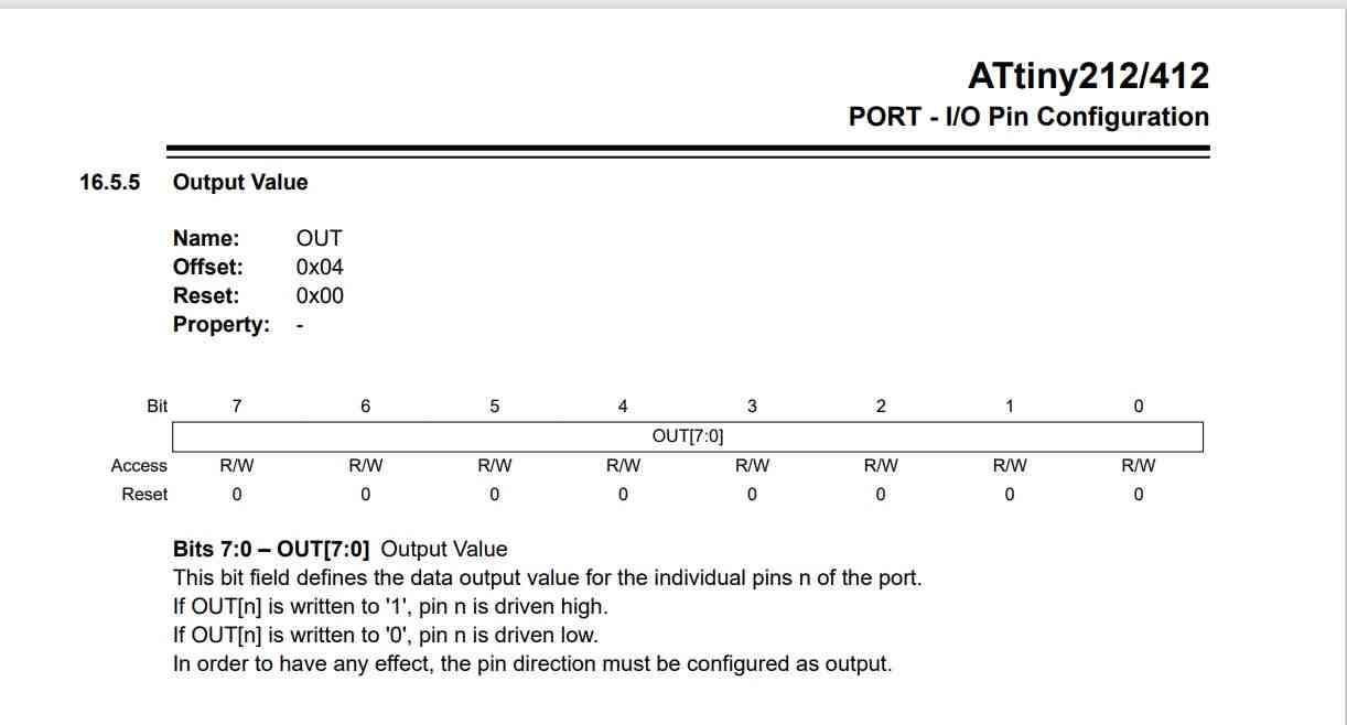
I typed out this #define output *((volatile byte *)(0x04)) as a variable to PORT.OUT. I ran this and my code didn’t worked. I noted that the memory location was labeled with offset and I did some research and came accross this image from this Youtube video
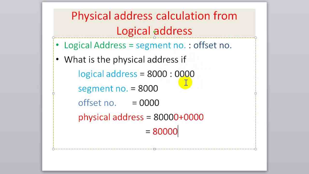
I realized that I had to encoporate the normal location and the offset location for the pointer. I looked for the PORTA configuration register and came accross this image
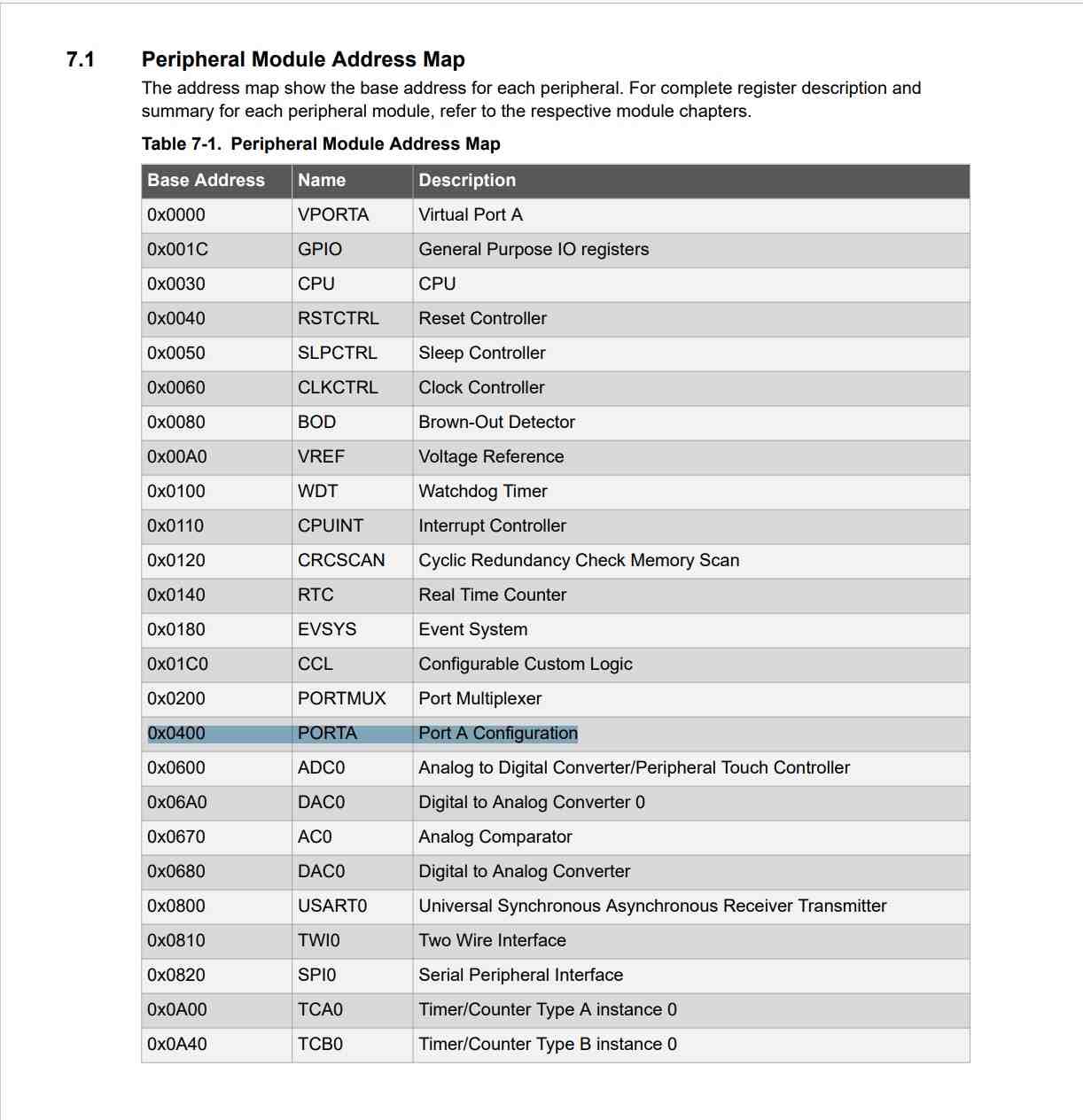
To fix the issue I typed #define output *((volatile byte *)(0x0400 + 0x04)), this would define my variable output to the exact register for output configuration. The 0x0400 is the PORTA register while the 0x04 is the output offset. I ran the code only changing out the output variables for this and my code worked. Using the same concept I changed all of corresponding registers to pointers. My final code for this is below
int ledPin = 1;

#define output *((volatile byte *)(0x0400 + 0x04))
#define input *((volatile byte*)(0x0400 + 0x08))
#define DataDirection *((volatile byte*) (0x0400 + 0x00))
#define Pincontrol *((volatile byte*) (0x0400 + 0x10 + 3*0x01))


void setup()
{
  DataDirection = B10000000;              // Defines OUTPUT as PA7 and INPUT as PA3
  Pincontrol |= PORT_PULLUPEN_bm; // Makes the button pin read as HIGH if button isn't pushed
  output = B10000000;
  input = B00001000;
}

void loop()
{
  if (!(input &= (1 << 3))) // Button Is Pushed
  {
    output &= ~(1 << 7); // LED will stay on B01111111
  }
  else
  {
    output |= (1 << 7); // LED turns off
  }
}
Problems I Ran Into
- Directly setting the bits instead of using normal bit masking
- Platform IO resetting my programmer
- My programmer no longer works
- Some of my files became corrupt so I had to redownload them
- Not fully understanding what each command did until the end
What I Learned
WOW, this week was a stressful one. Who knew simply making an LED would take hours upon hours of research and reading? The knowledge I gained this week, with bare-metal programming, integrating a new IDE, and learning how to read a datasheet is important. However, I feel the most important lesson from this week is that I realized what makes an Arduino work. Terms such as registers, reset, DDR, and ports were completely unknown to me until this week. I learned what makes an Arduino function when I type in the terms digitalWrite and digitalRead. I learned how memory works, and even with my little experience with C++, I feel like I understand conceptually how some of it works. I learned that there is an easier way to code an Arduino with Platform IO in VSCode. The best way to describe this experience is comparing it to what I did during week 5 Electronics Production. That week I created a board with a microcontroller and figured out how to work it. After this week, I feel like I understand why it works.
Group Assignment
This weeks group assignment was to compare the performance and development workflows for other architechtures. Myself and Alaric Pan decided to work on the Jetson Nano. The group page is located here
Files
My final code file is here