11. Input Devices
Assignment: Add a sensor to a microcontroller board that you have designed and read it.
Understanding and How to Read RFID Readers
The week I am using an RFID-RC522 reader as my input. It requires SPI communication which means the pins that it uses on the ATTiny1614 is MISO, MOSI, SCK, and SS. I will have to directly connect the MISO, MOSI, and SCK pin directly to the RFID reader, however the SS pin can either be used directly in the pin or I can just set a random pin as high.
These were some helpful links
To read the values from the ATTiny1614 in the serial monitor I must connect the RX and TX pin. Those pins work in vice versa so RX on the controller goes to TX on my programmer or serial to FTDI converter, while TX on the controller goes to TX on the converter.
The programmer I created in week 5 has TX and RX pins, however the TX pin acts as the UPDI pin when I jump the wires. There are a multitude of options to read the data from the RX and TX pins from the microcontroller such as
-
There are FTDI to USB converters that have RX and TX pins, I can plug that into my computer along with my programmer without configuring anything and just make sure to read the serial port from the FTDI converter. I would have to download CoolTerm, a serial port reading software. I would have to share a common ground between my board, my programmer and my converter. Unfortunately, I don’t have 2 USB ports in my computer.
-
My other option and the option I will be choosing would be to make my programmer act as a serial monitor reader (FTDI). First, I would have to program my board using my normal method, documentation is located here. After the board is programmed, I have to adjust the code for my SAMD11C programmer from
Serial1.begin(57600, SERIAL_8E2);toSerial1.begin(57600);I have to make sure that the SERIAL_8E2 is deleted while also keeping the baud rate the same for my ATTiny1614 program and the serial UPDI program. I will choose 9600 as the baud rate to keep it the same. Since the controller is already programmed, I can just provide power and ground from the programmer while also configure the TX and RX mentioned earlier.
The code I used to convert the programmer is below
void setup() {

   SerialUSB.begin(0);
   Serial1.begin(9600); //Adjust baud rate and use SERIAL_8N1 for regular serial port usage
}

void loop() {
   if (SerialUSB.available()) {
      Serial1.write((char) SerialUSB.read()); //Send stuff from Serial port to USB
   }
   if (Serial1.available()) {
      SerialUSB.write((char) Serial1.read()); //Send stuff from USB to serial port
   }
} //end loop
Coding With Arduino
Adding External Libraries To Arduino IDE
First, I needed to get the ID number from the card. To do this, I used the two links above and the libraries below.
#include <SPI.h>#include <RFID.h>
The SPI.h library should already exist in the arduino library catalog. However, the specific RFID.h library that I used does not.
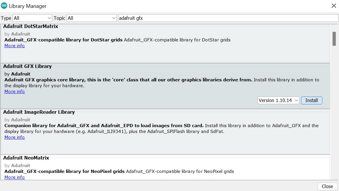
To add the library to the arduino IDE, their are a couple of steps. I used the official arduino documentation to install the library.
Here is the library file
Reading ID Tag Number
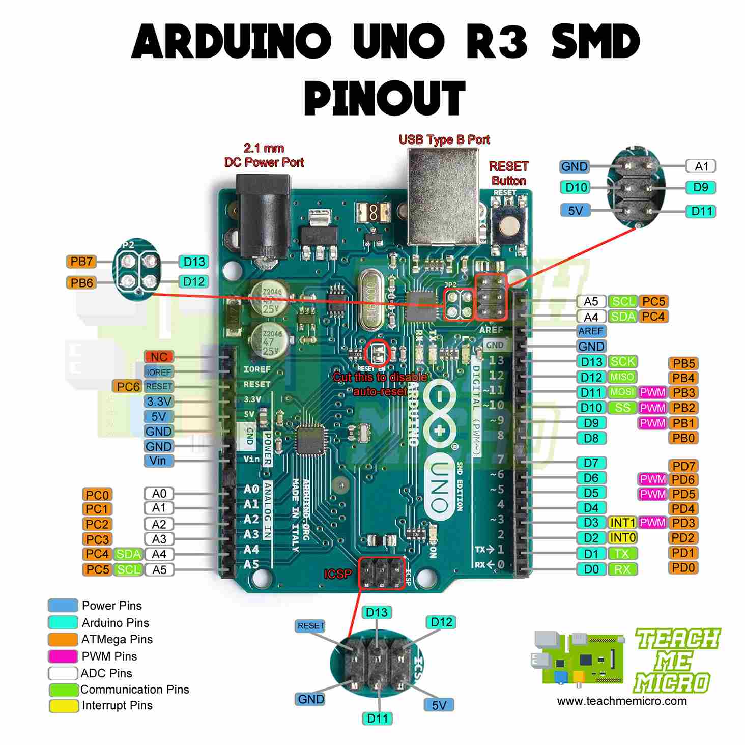
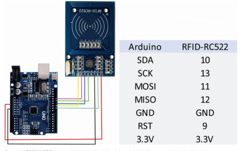
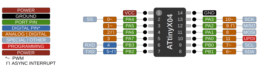
Once libraries were installed, I followed the documentation for pluggin in the pins on the RFID card with the pins on the Arduino. Looking at the datasheet it requires 3.3V so I plugged it into the 3.3V in the Arduino. Using this image of the Arduino pinout along with the image from the website of where to plug in the RFID pins made the configuration easy.
I uploaded this code using the arduino IDE because platform IO required that I download the libraries. The code is below
#include <SPI.h>
#include <RFID.h>
#define SS_PIN 10
#define RST_PIN 9
RFID rfid(SS_PIN, RST_PIN);

String rfidCard;

void setup() {
  Serial.begin(9600);
  Serial.println("Starting the RFID Reader...");
  SPI.begin();
  rfid.init();
}

void loop() {
  if (rfid.isCard()) {
    if (rfid.readCardSerial()) {
      rfidCard = String(rfid.serNum[0]) + " " + String(rfid.serNum[1]) + " " + String(rfid.serNum[2]) + " " + String(rfid.serNum[3]);
      Serial.println(rfidCard);
    }
    rfid.halt();
  }
}
I then wanted to try using the RFID reader with my OLED screen. I had to do some research on how they work along with what libraries to download and I came across this video by DroneBot Workshops. The video instructed me to download the Adafruit libraries from the Arduino IDE, meaning that I couldn’t use this platform IO also.
After downloading this and watching more of the video I was able to get my RFID reader to activate the OLED screen. The datasheet says that it requires 5V to operate, which was diffierent than the RFID card so I could use the arduinos 5V port fort he OLED while also using its 3.3V for the RFID.
ATTiny1614
KiCad
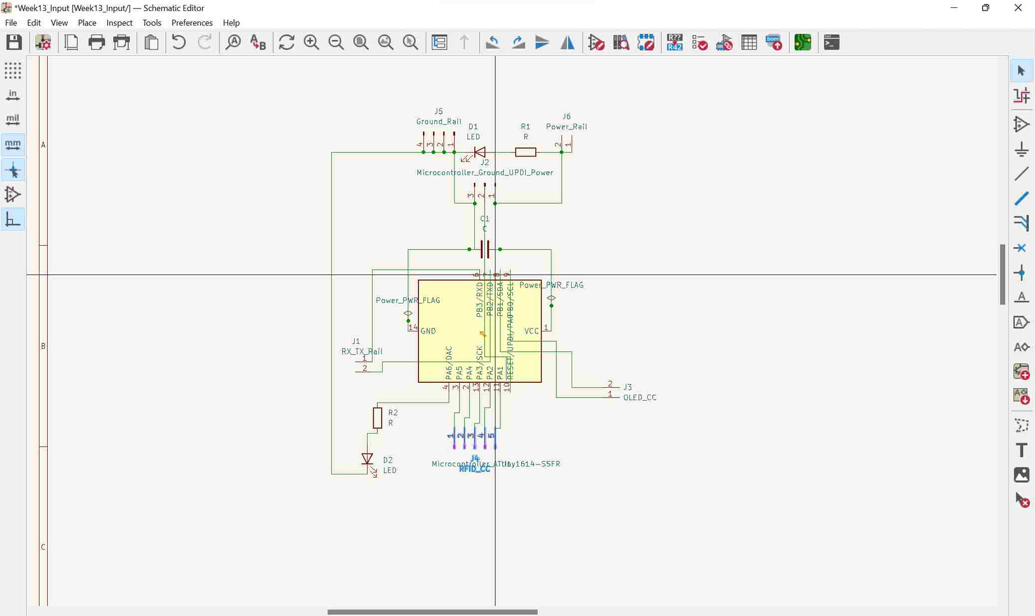
KiCad Schematic Editor
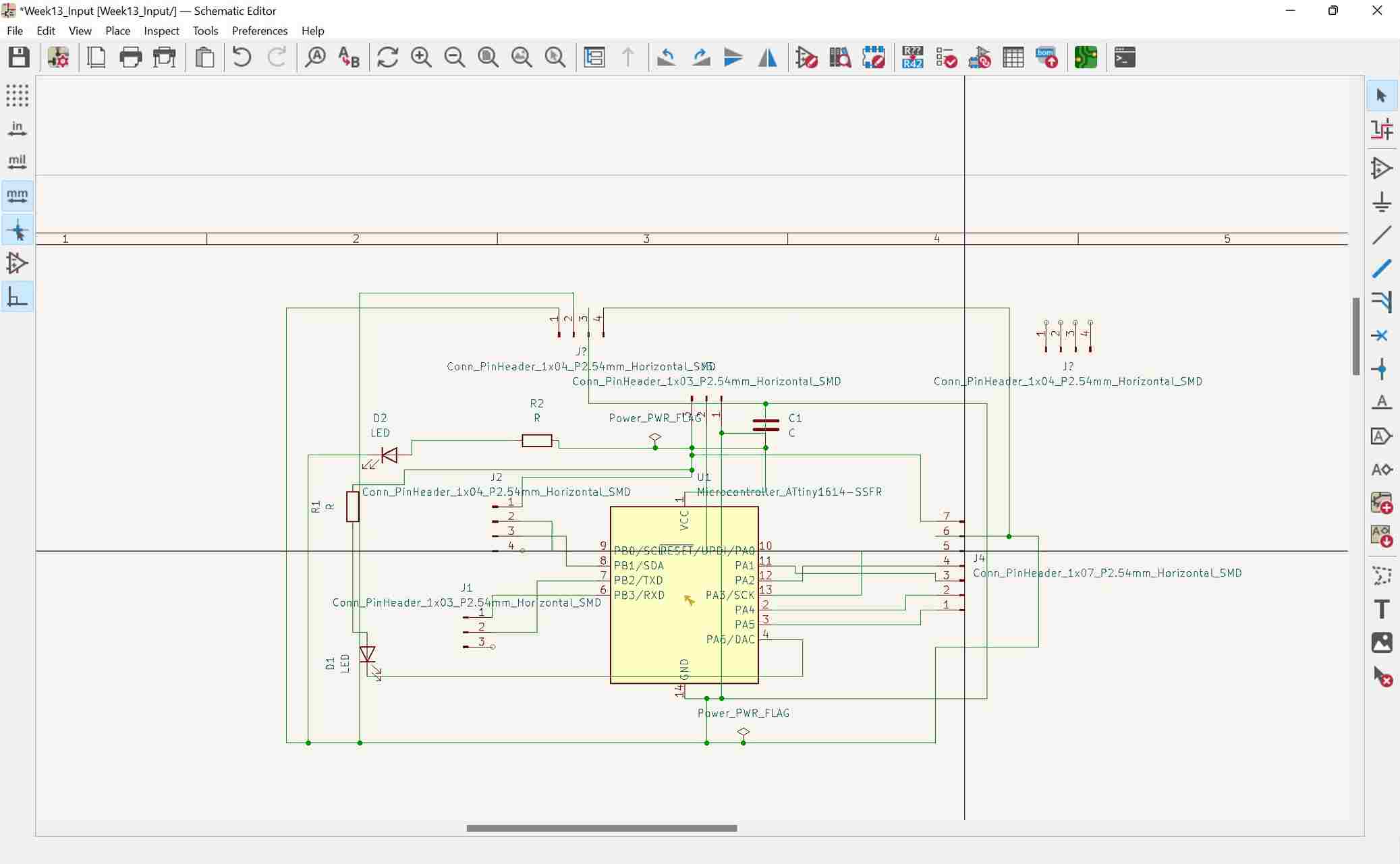
This was my hardest board up to this point to use. I needed to add headers for the RFID card with 7 pins from the microcontroller connecting to it. SS, RST, MISO, MOSI, SCK, GND and PWR. I also wanted to include my OLED screen. Looking at the datasheet and pinout it uses I2C communication. which requires 4 pins SDA, SCL, GND and PWR. I also needed 3 pins for my serial communication which used pins RX, TX, and GND. Finally, I wanted to add 2 LEDs, one to indicate power, and the other as a program (which would come in a lot of help). I used my earlier documentation to help with the process. Using the schematic editor was simpler than the PCB editor because you can cross over wires, and with everything connected and no errors I moved on to the PCB editor. I used my earlier documentation on how to connect the wires and get rid of any errors I encountered during the process. A major difficulty I encountered was trying to connect common grounds and keeping track of which pins were already connected to the common ground wire.
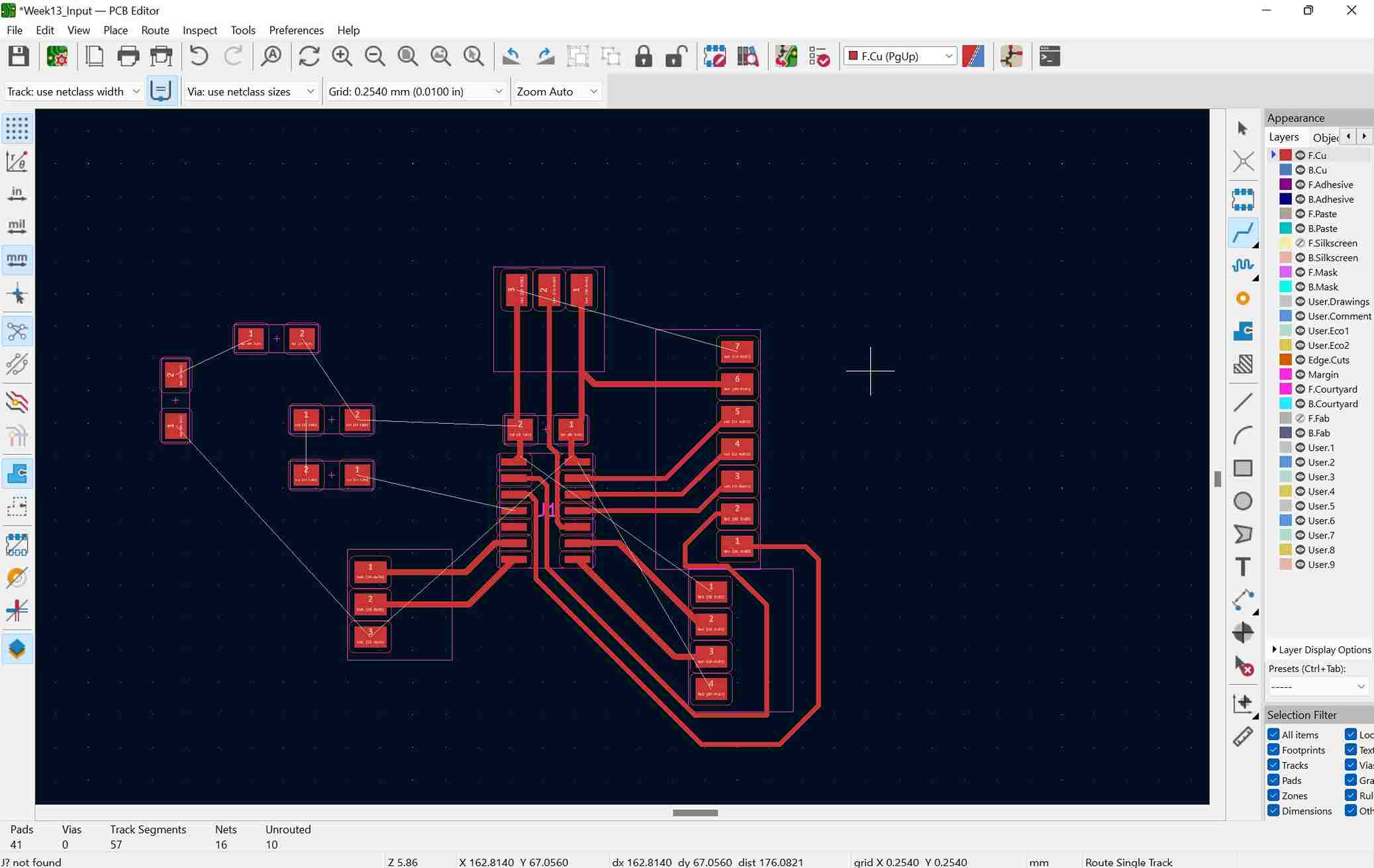
KiCad PCB Editor
I had to make one change to the constraints in the PCB Editor.
- Trance Clearance Constraint: Changed from 0.5mm to 0.4mm to fit traces through microcontroller.
This is where I experienced some problems. Connecting the programming pins to the headers was a simple process because of how I designed it in the schematic editor, however I didn’t think of how to connect common ground and power. The power trace had to travel a long distance to reach the headers for the OLED and the RFID card. The ground was even more complicated because every component needed a trace connecting them. After spending hours on trying to work my way, I found myself in a rabbit hole and decided it was best to restart from scratch. My final design before restarting is below.
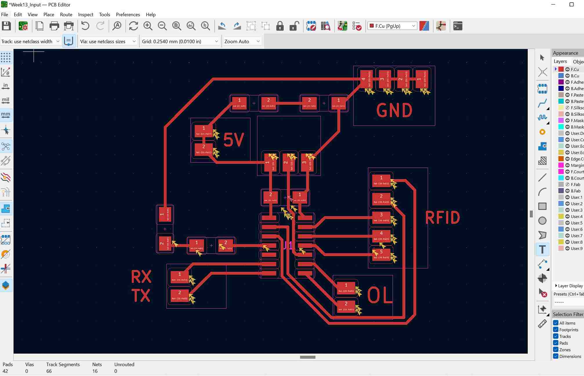
Revisions
Going back into the schematic editor, I decided creating power and ground rails. I proposed the idea during Machine week to consolidate all of the drivers and wires and it worked to perfection, so I decided to bring the same concept here to my personal board. Instead of using 4 pins and 7 pins for the OLED and the RFID with 3 pins for serial communication, I simplified it to 2 pins for OLED, 5 pins for RFID, and 2 pins for serial communication. I then added a new 2 pin header to act as power, with a 4-pin header (all of the traces connected) acting as common ground.
I added these, went back into the PCB editor with a much clearer plan and I was able to construct the board in less than 30 minutes. I used my earlier documentation to plot the files, since I was only using surface mount soldering, and went to the milling machines in the lab to create the board.
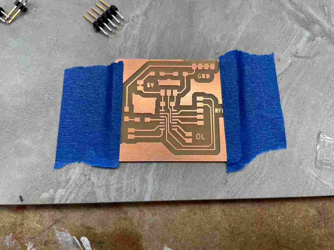
Milling
I used my earlier documentation except I made a change.
- Trace Clearance: 2.00mm
- Trace Depth: .20mm
After that I placed the copper in, probed the material thickness, then changed the bit, uploaded my FCuts along with the Edge.Cuts and milled out the board.
Redesigning Board
I went back into the KiCad PCB editor and decided to make a few changes because the board I had first milled wasn’t as good as it could be. The traces under the microcontoller stayed at a value of 0.4 mm, but I changed the values of every other trace to 0.5 mm. I normally used 0.5 mm and I have never ripped a trace until I changed it to 0.4 mm. I forgot to add a regulator for the voltage of the RFID, so I couldn’t include the OLED display because it requires 5V to operate. I went back to program the board. I plugged in everything and made sure that the programmer was set to 3.3v because of the RFID card.
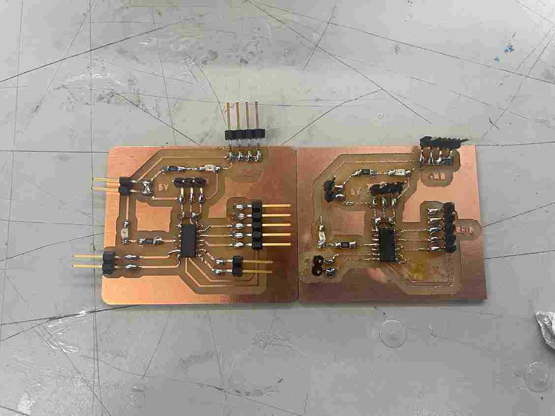
I milled out this board and instead of soldering vertical headers I used horizontal headers.
As you can see the new board on the left was much better than the one on the right
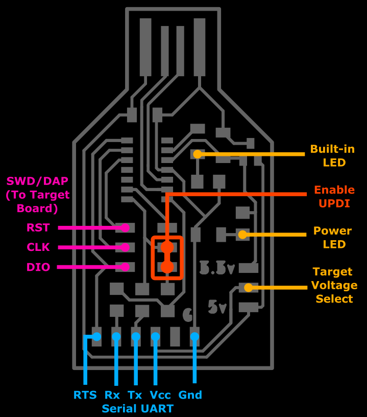
Converting Programmer to FTDI Serial Reader
Using my programmer pinout, I connected the TX of the programmer to the RX of the board, and similarly the RX of the programmer to the TX of the board.
I used this code mentioned earlier
void setup() {

   SerialUSB.begin(0);
   Serial1.begin(9600); //Adjust baud rate and use SERIAL_8N1 for regular serial port usage
}

void loop() {
   if (SerialUSB.available()) {
      Serial1.write((char) SerialUSB.read()); //Send stuff from Serial port to USB
   }
   if (Serial1.available()) {
      SerialUSB.write((char) Serial1.read()); //Send stuff from USB to serial port
   }
} //end loop
Coding
I connected the pins or the RFID reader to the board looking at the ATTiny1614 pinout on my board.
I then programmed the board using this code.
#include <SPI.h>
#include <RFID.h>
#define SS_PIN 0
#define RST_PIN 1
RFID rfid(SS_PIN, RST_PIN);

String rfidCard;

void setup() {
  Serial.begin(9600);
  Serial.println("Starting the RFID Reader...");
  SPI.begin();
  rfid.init();
}

void loop() {
  if (rfid.isCard()) {
    if (rfid.readCardSerial()) {
      rfidCard = String(rfid.serNum[0]) + " " + String(rfid.serNum[1]) + " " + String(rfid.serNum[2]) + " " + String(rfid.serNum[3]);
      Serial.println(rfidCard);
    }
    rfid.halt();
  }
}
Using the steps mentioned earlier in the documentation, I switched my programmer to a serial monitor reader by changing the code of the programmer, un jumping the UPDI enabler pins, connecting the RX pin to the TX of my board and vice versa. I openned the serial monitor reader recieved a weird signal. It was just symbols that looked like question marks.
At first I thought it had something to do with the code, so I started altering the code, then I thought it was a library issue, but realized it wasn’t because the library wouldn’t compile unless it worked. The then thought it had something to do with the traces, concidering I already ripped the two that went to the OLED screen. After talking with Mr. Dubick, he thought it was a baud rate issue because I was at least recieving a signal from the microcontoller.
I used the same code as earlier for my board, making sure the baud rate was 9600. I then used the same code earlier for my programmer to make it a serial device, also checking that the baud rate was at 9600. I uploaded the code to the programmer then plugged it into my computer while also connecting the board, and I was able to recieve the RFID card ID number.
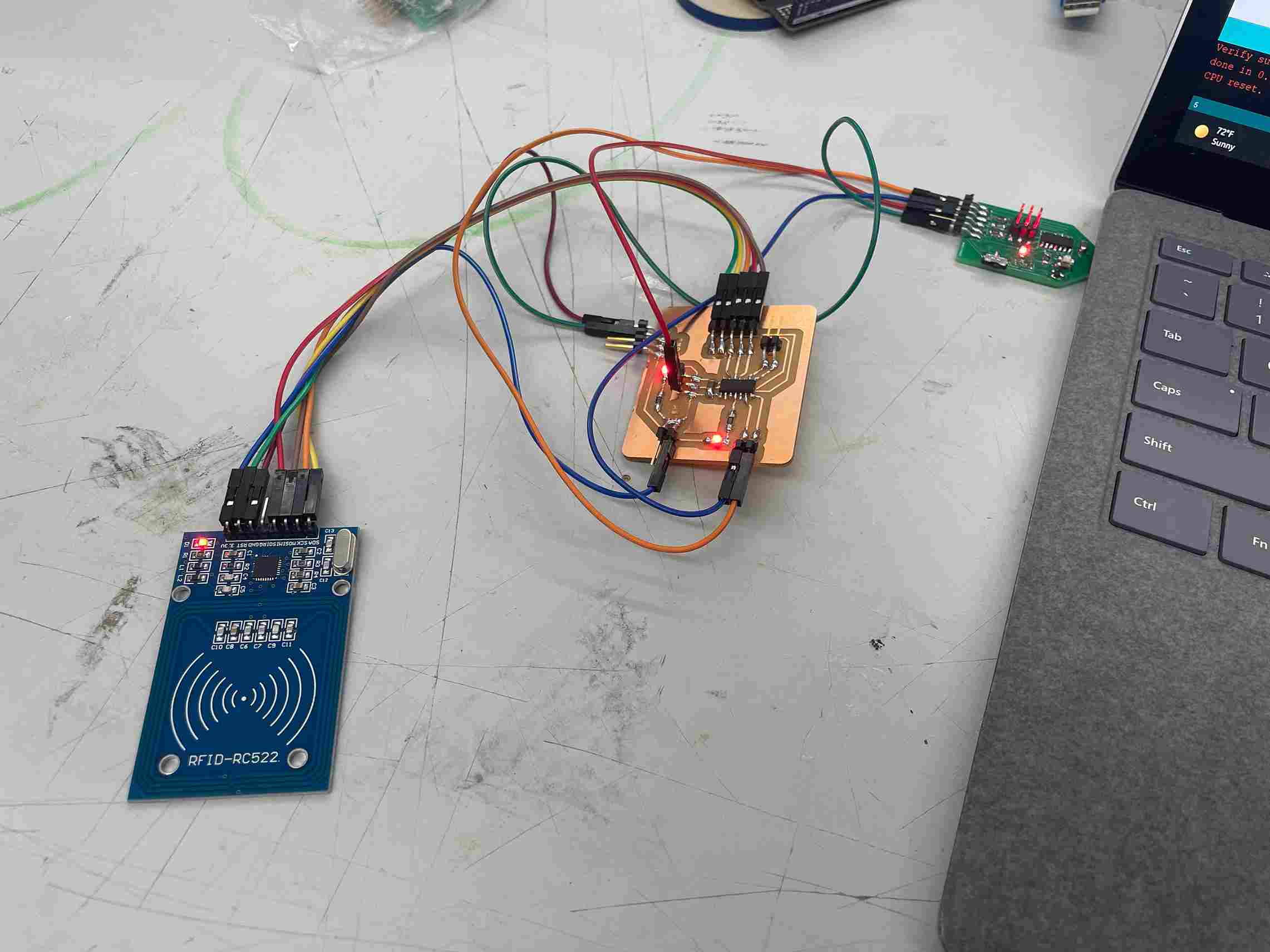
I wanted to test that I could blink the built in LED on the board using the RFID card, so I ran this piece of code using the RFID and SPI library and it worked.
#include <SPI.h>
#include <RFID.h>
#define SS_PIN 0
#define RST_PIN 1
RFID rfid(SS_PIN, RST_PIN);

String rfidCard;

void setup() {
  Serial.begin(9600);
  Serial.println("Starting the RFID Reader...");
  SPI.begin();
  rfid.init();
  pinMode(2, OUTPUT);
}
void loop() {
  if (rfid.isCard()) {
    if (rfid.readCardSerial()) {
      rfidCard = String(rfid.serNum[0]) + " " + String(rfid.serNum[1]) + " " + String(rfid.serNum[2]) + " " + String(rfid.serNum[3]);
      Serial.println(rfidCard);
      if (rfidCard == "124 98 66 24") {
      digitalWrite(2, LOW);
      } else
      {
        digitalWrite(2, HIGH);
      }
    }
    rfid.halt();
  }
}
What I learned
I watned to encoporate my input with my final project. I want to design so everything activates once the RFID card is scanned. To do that I had to learn a lot about SPI and how that functions, along with learning about different types of communication such as I2C for my OLED. I also learned a lot about how the serial terminal functions and how to use it to test if I am recieving or sending out the data I need. The programmer I made had a lot more uses than I realized and I’m beginning to understand how it actually functions.
Problems I Ran Into
- Milling a bad board
- Not checking the baud rate on both the serial programmer and my board
Group Assignment
The group assignment this week was to probe an input device(s)’s analog and digital signals. I worked with Jack Donlly and Nick Niles for this week. We measured the analog signal coming from his water sensor. As water touched the sensor it would give out an electrical signal that we could measure. I worked with helping calibrating the oscilloscope and wiring. The link to the group site is here