10. Molding and Casting
Assignment: Design a mold around the stock and tooling that you’ll be using, mill it (rough cut + three-axis finish cut), and use it to cast parts
Idea
I initially wanted to create something for my final project. I would need a flexible mold that could hold the glasses in place while the servos are spinning. After working on the group project, I realized that mold star would be the best mold to use for the pieces. I went into fusion and started designing. I knew that I would have a slot that was the width of my glasses and because the material was flexible, I could create another slot that was around ½ the width of my glasses. After designing for around 4 hours, I came up with this design
There was one tiny problem. The width of my glasses is WAY too thin for any bit in the lab to cut through. I considered the idea of resin printing; since it uses a laser to cut out a design. Since this process uses a 3D printer and not a milling machine, they are out of the scope of this week’s assignment. I would later change the design for the holder and use the resin printer. For my documentation, you can look at my final project page.
My next idea was to create a mold for the Spider-man PS4 logo. It was a simple design, and it would be cool to have a hardened version of it. I went through the whole process of designing it and I made some mistakes along the way.
- I created a design too big for the piece of clay that I had
- The extrusion was too large, and the design would take 4 hours (I would find out later that this is only because of the Fusion 360 settings)
- I didn’t add a tray for the resin to pour into after the milling was finished.
I would get to the 3D adaptive and tool path section until I realized that my design was too close to the edge of the tray and the bit wouldn’t be able to through it. I thought that I could scale the design down to troubleshoot the problem. This didn’t work because the spaces in between the spider legs were too thin for the bit to pass. I decide to do another logo
Designing
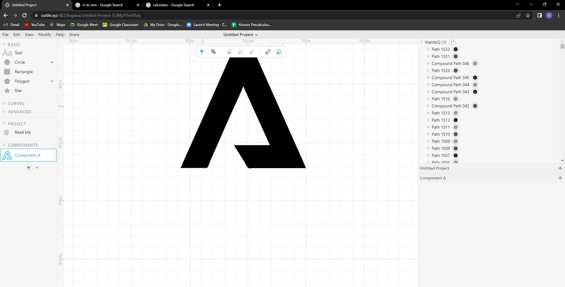
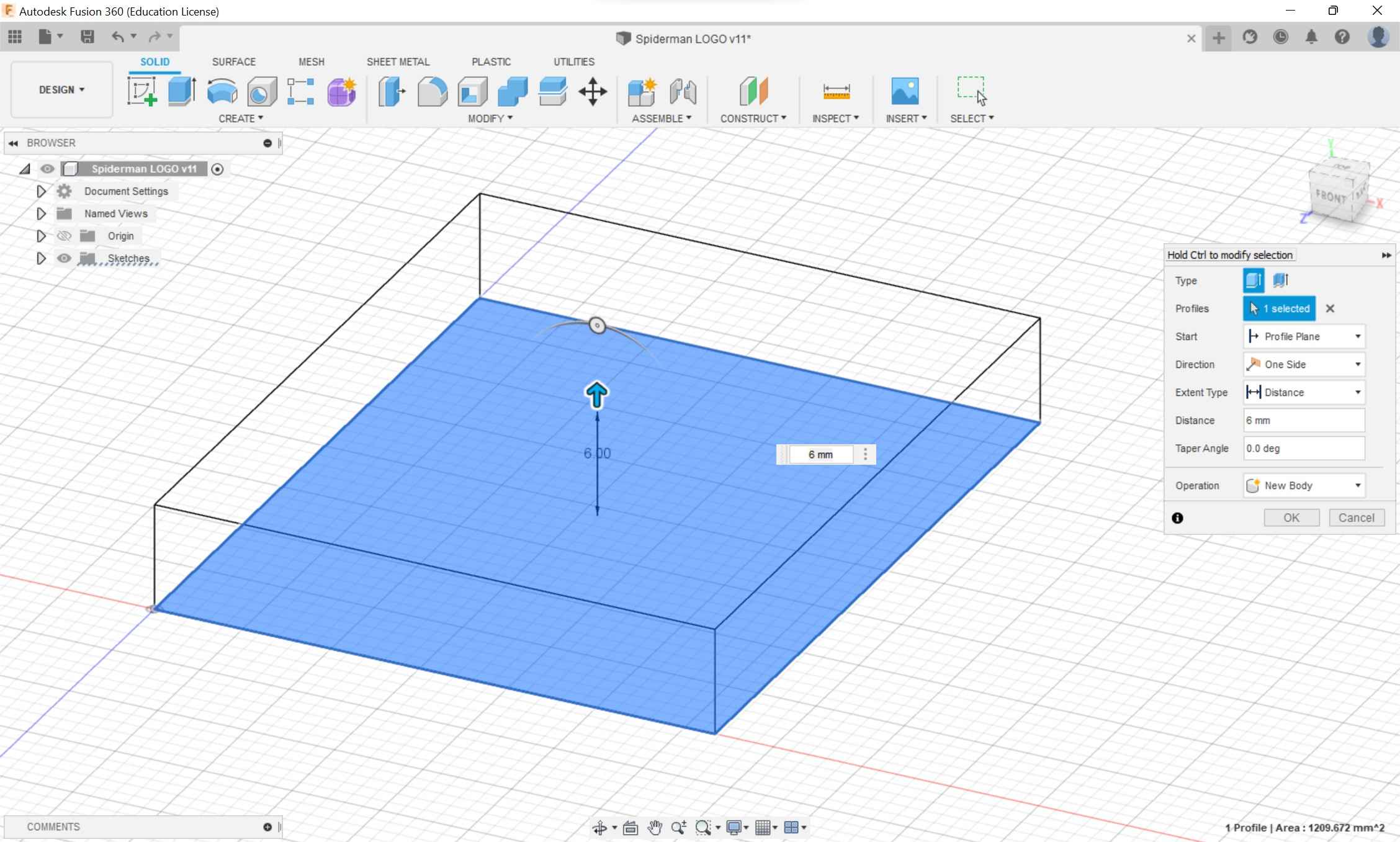
I decided to use a simple logo from one of my favorite Xbox games Titanfall 2. After two attempts at creating a design, I was used to the process. I started by measuring the clay piece I would be using for the milling. I then created a box that was a couple of millimeters shorter. I then created a cube out of this shape that would act as the tray that the resin would pour into.
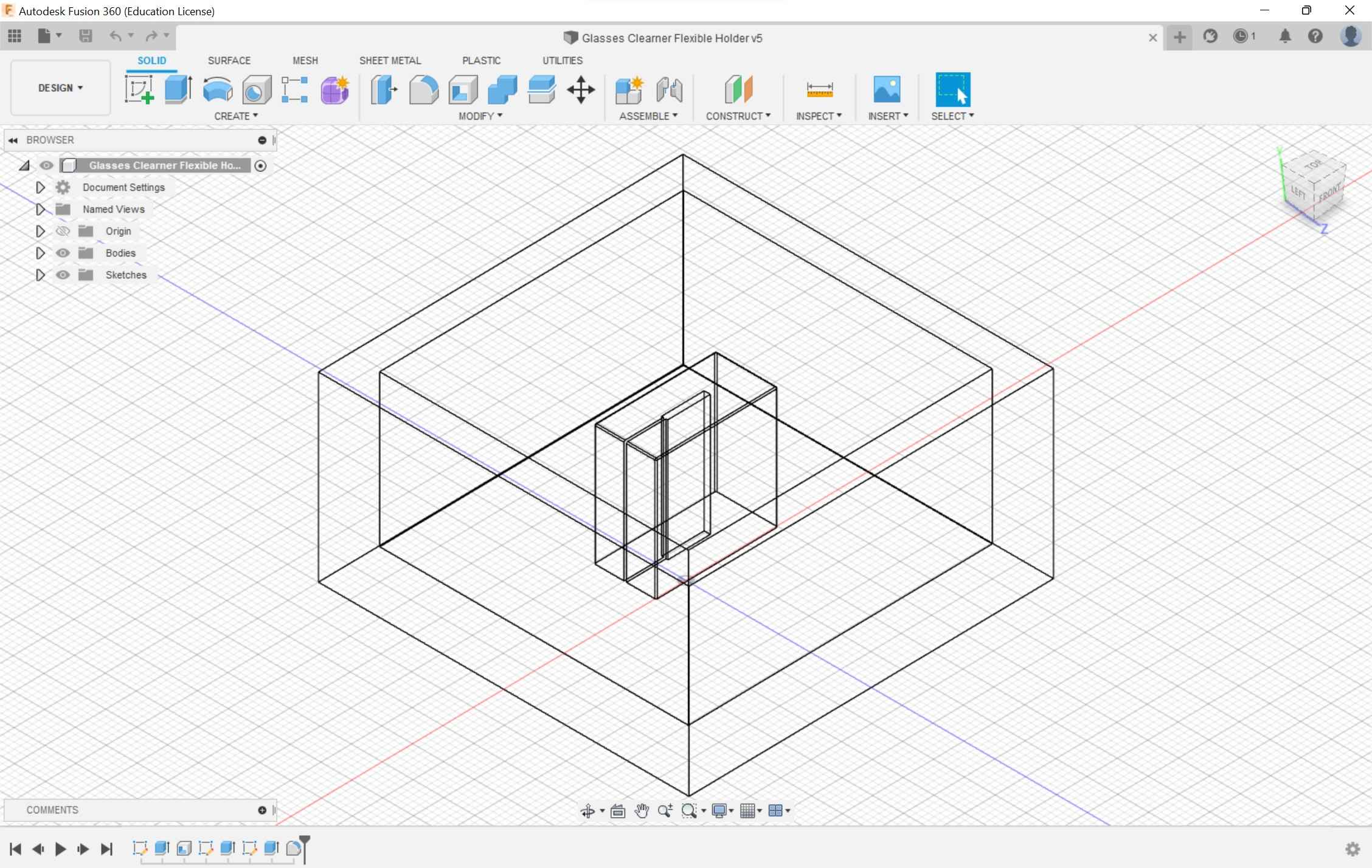
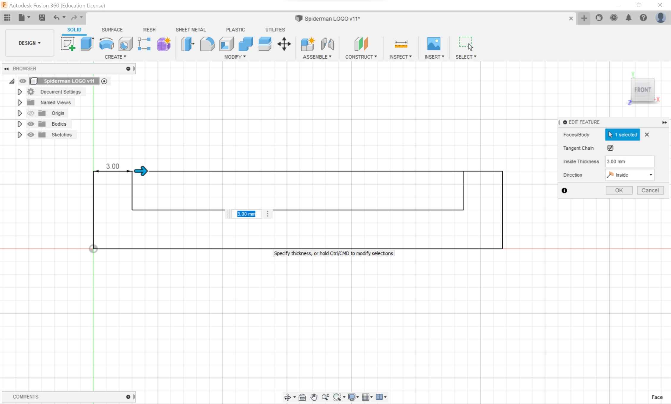
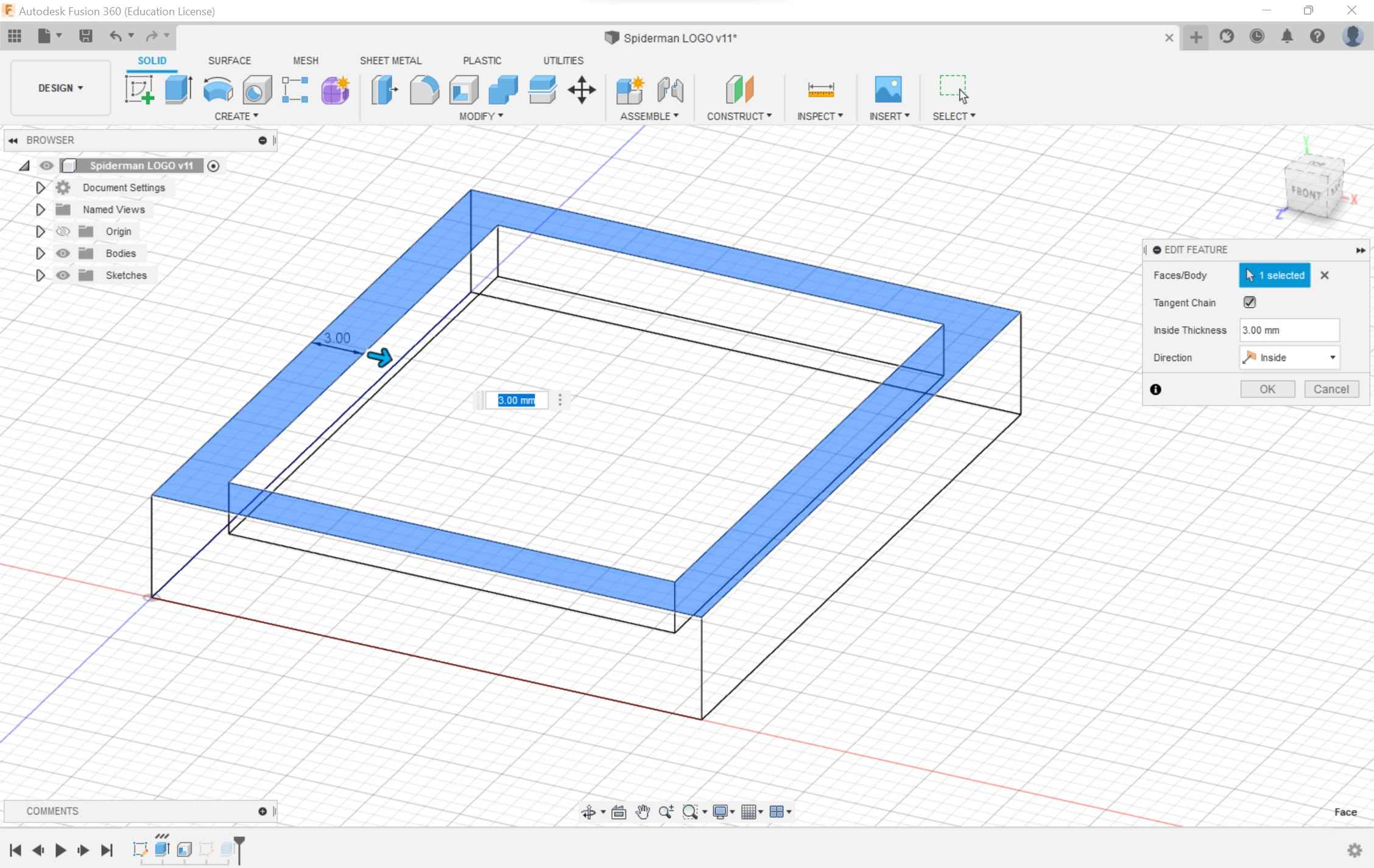
The next step was to create a shell of the cube. If I selected both the top and bottom faces, I realized that it would create two bodies when I got to the manufacturing side. Having two bodies would mess up the simulation and would mess up the toolpaths. If I shelled the design from one face and then pasted the logo SVG on the elevated plane when I would manufacture the design, it would create one body.
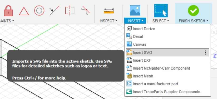
I imported the SVG and scaled the logo to fit considering the distance the logo was from the side of the design.
![]()
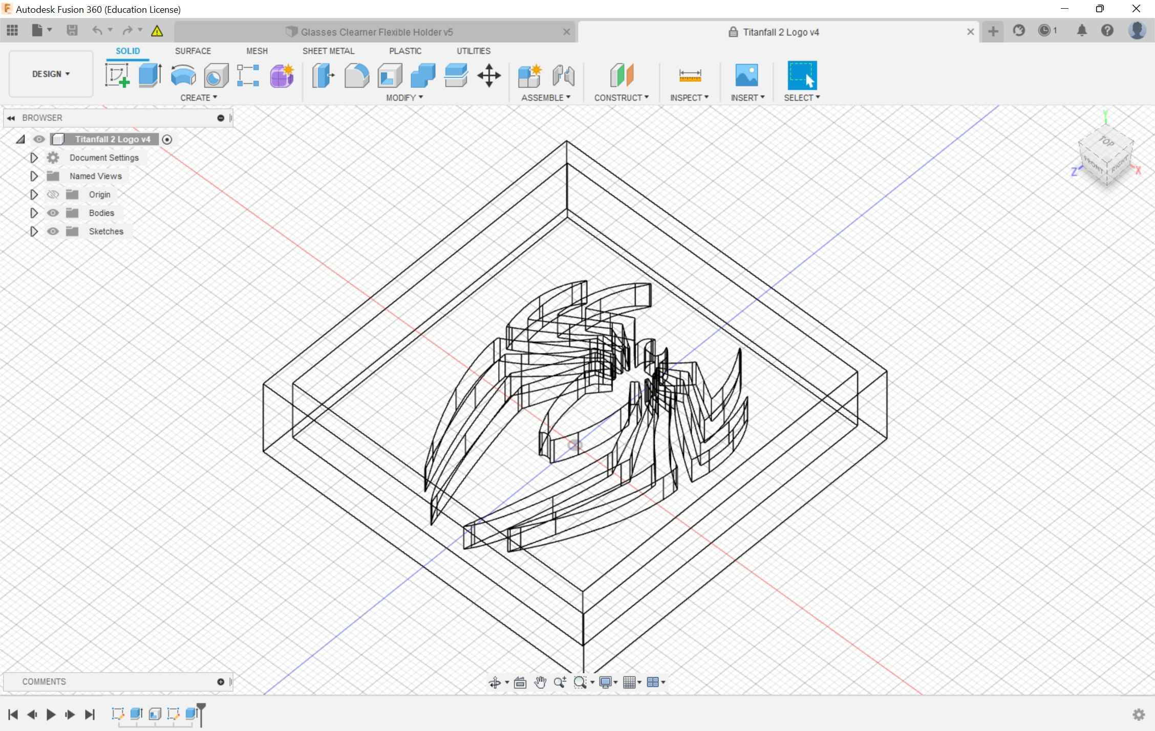
I extruded the logo
![]()
Then my design was ready to manufacture.
![]()
Manufacturing
For most of the manufacturing, I followed this workflow by Emily A. The document was clear, concise, and easy to follow. I highly recommend this to any beginner of using Fusion 360 for CAM
Setup
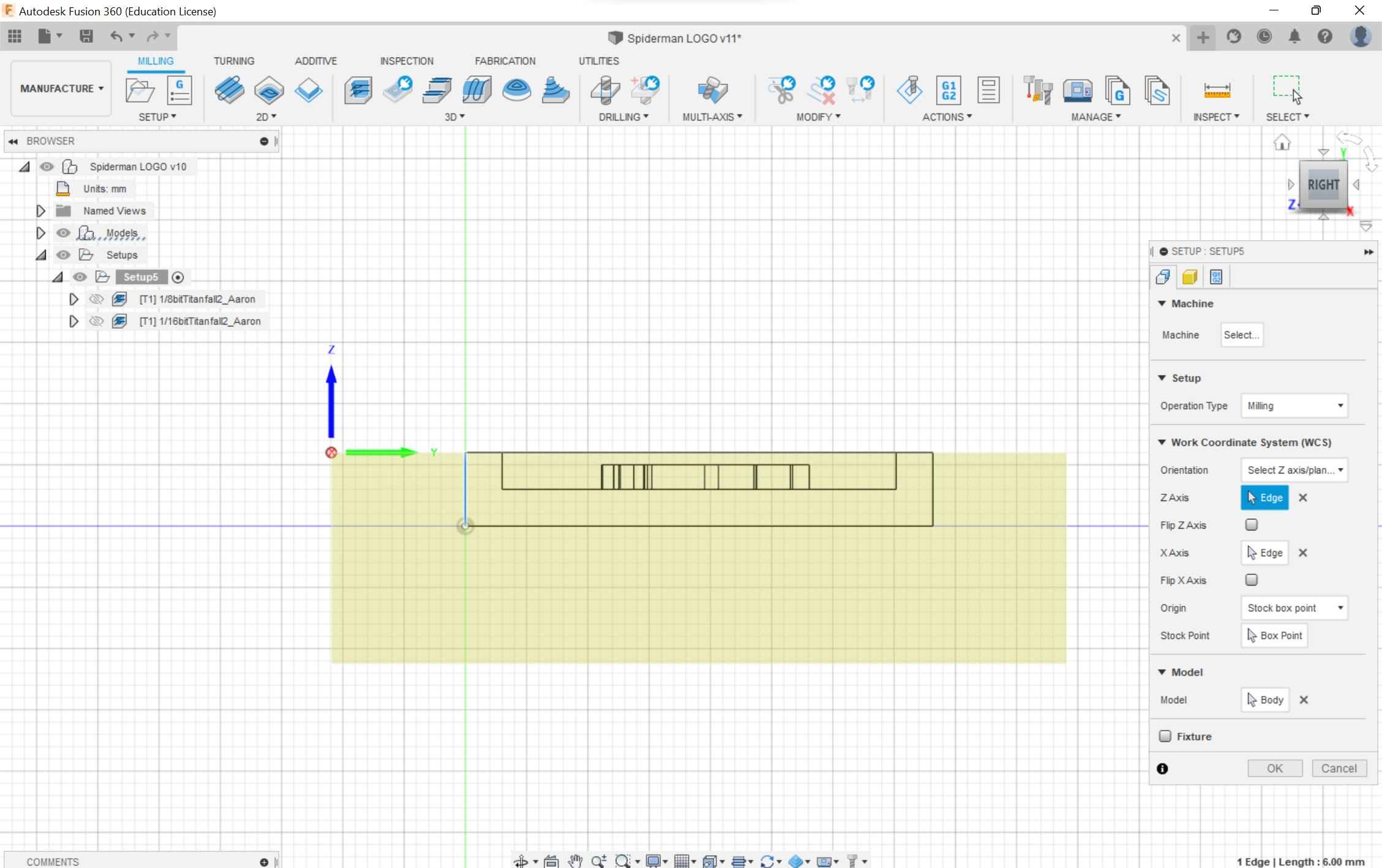
Following the documentation, I went into the manufacturing section of Fusion 360. I clicked on the setup menu and the first part to edit was the axis orientation. I selected the z-axis/plane & x-axis and started configuring the axis. On the othermill the z-axis was up and down, the x-axis was going right and left, and the y axis was going back and front. I configured this then set the origin as stock box point and selected the top corner. The model section showed 1 body which is correct. Earlier it was two but after I made the sketch on the shell plane this error was fixed.
In the stock section, I added the dimensions of the clay that I was using.
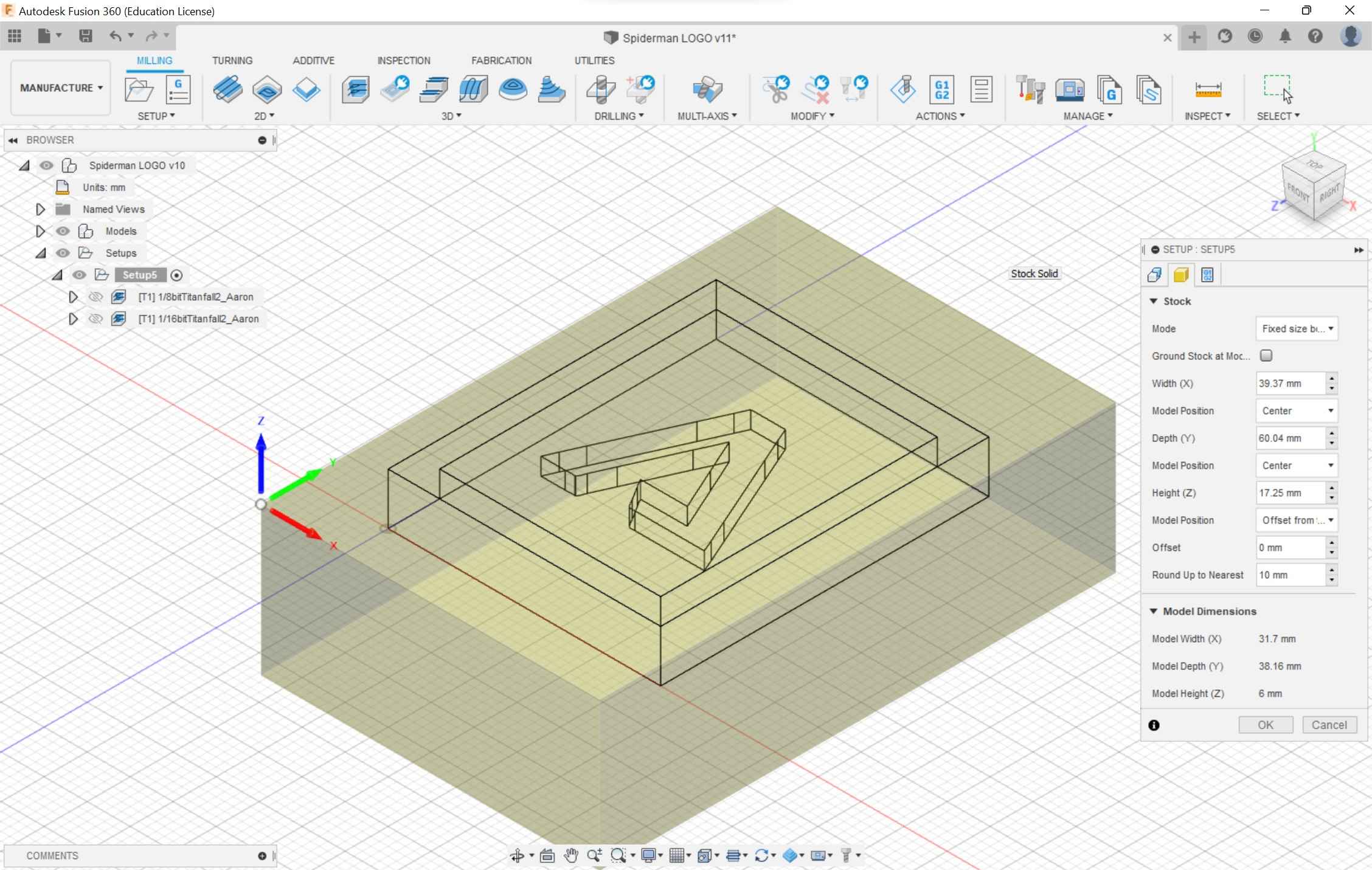
I made the model position center for the x and y-axis but for the z-axis, I created an offset of 0 mm from the top, so I didn’t waste material.
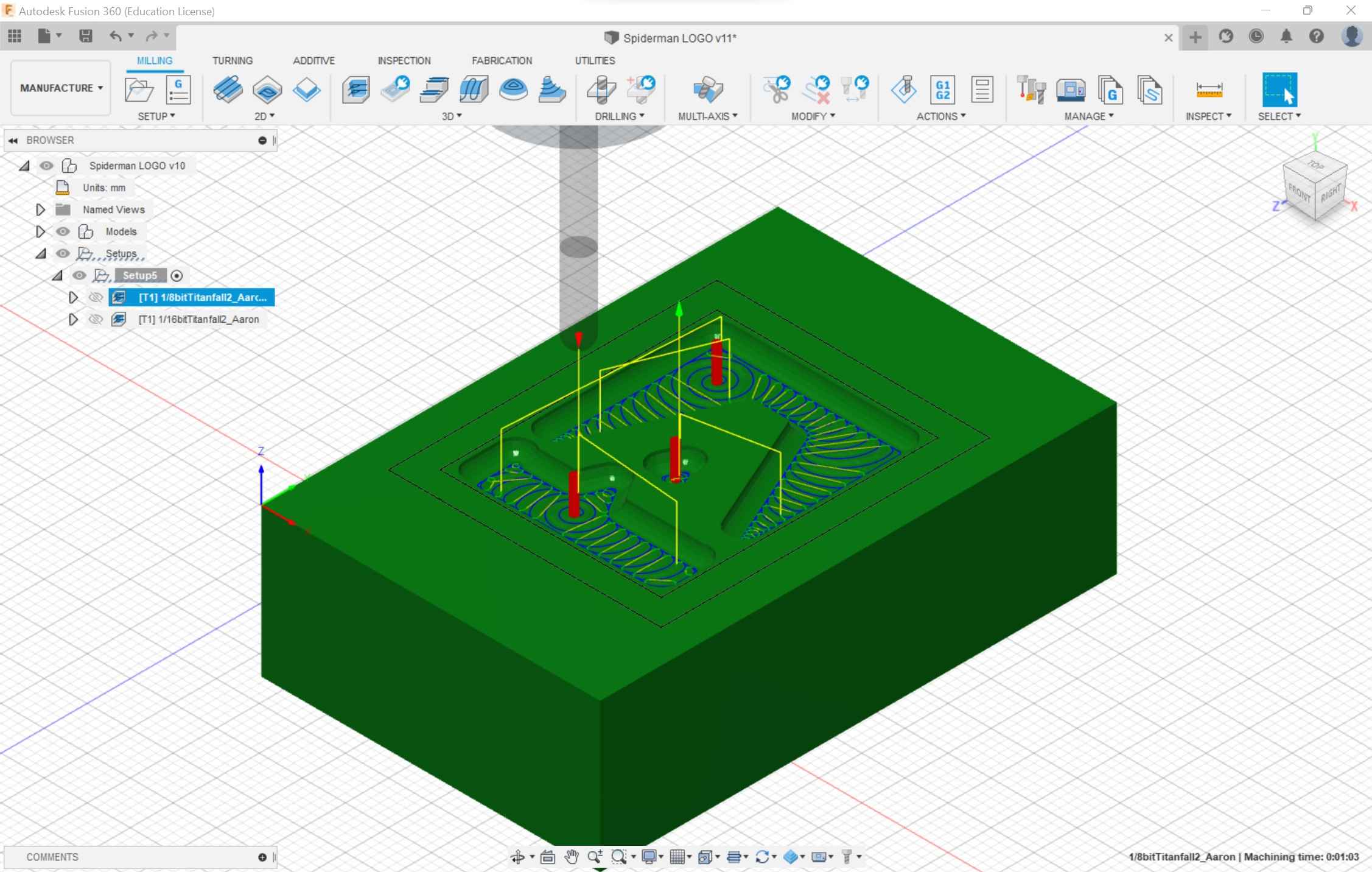
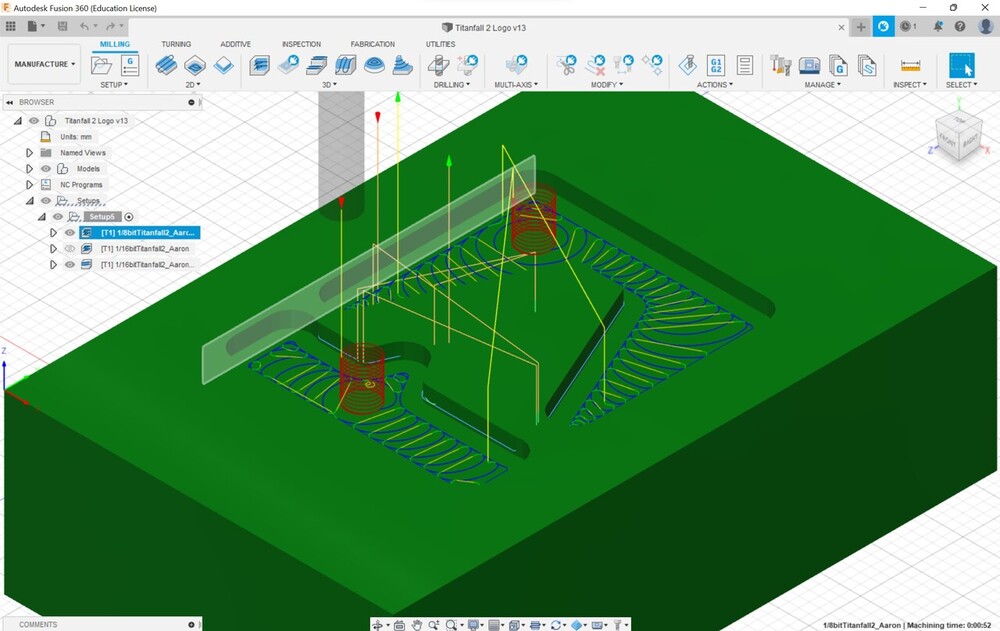
Toolpaths
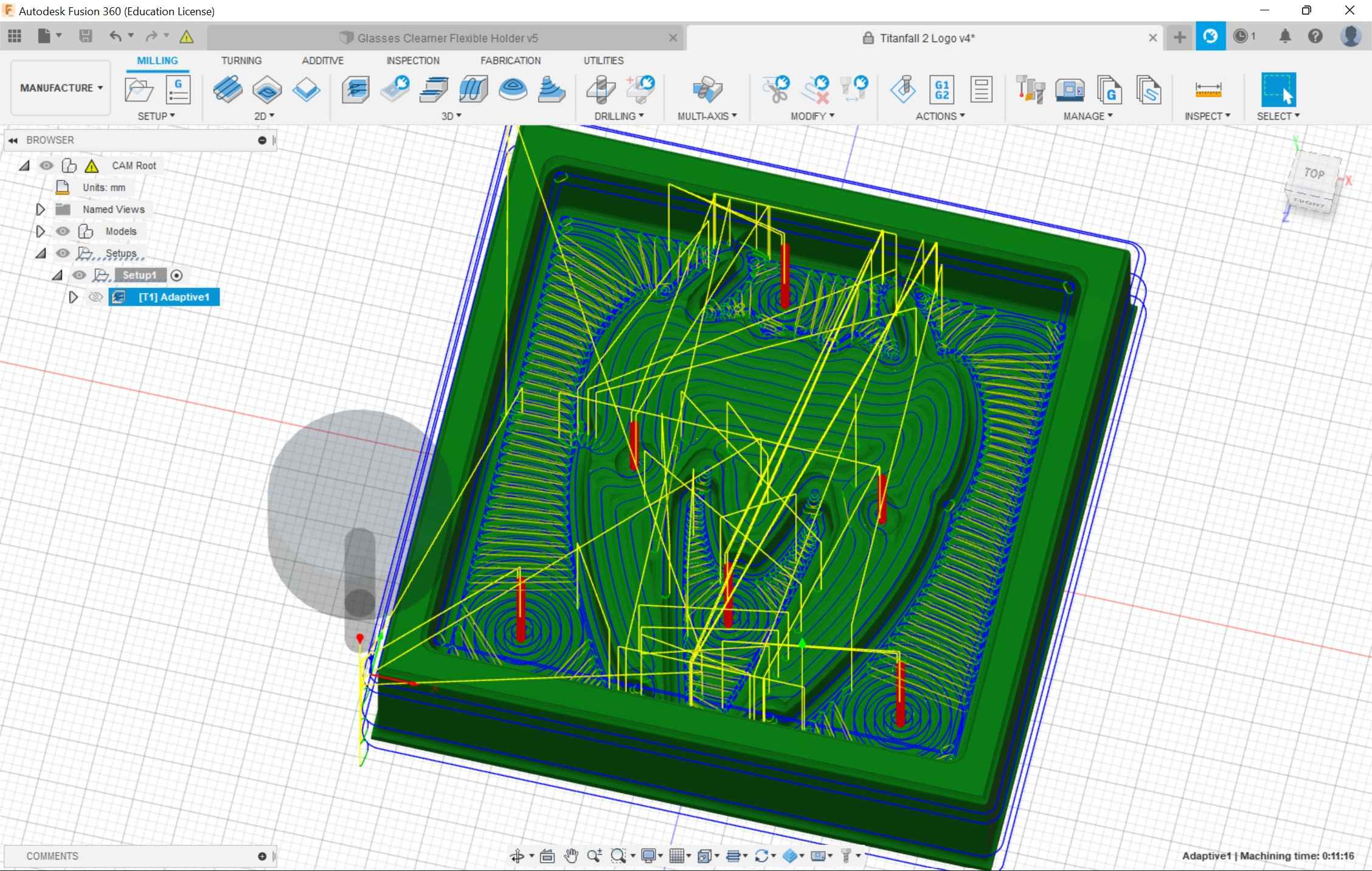
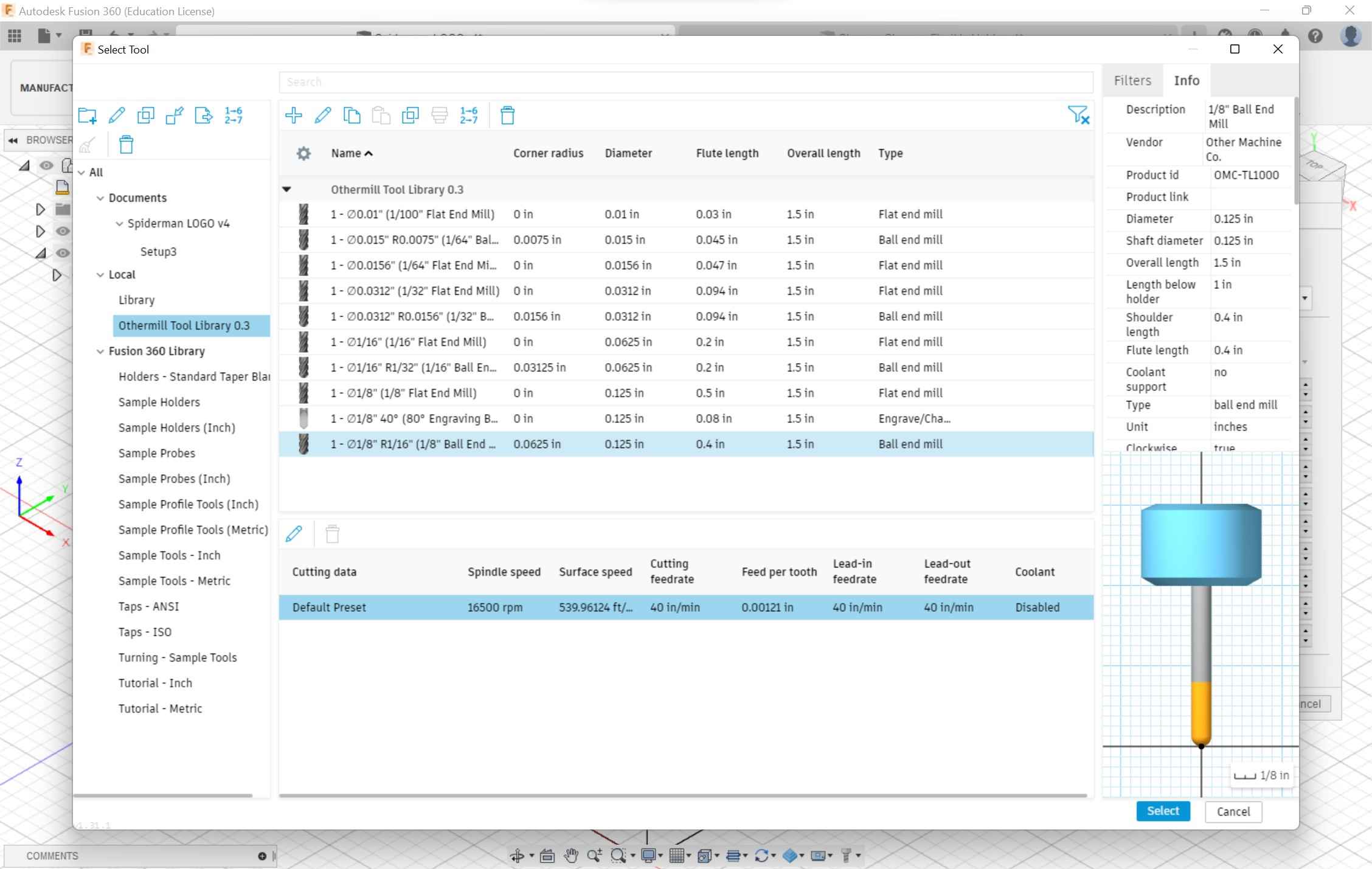
I clicked on the 3D adaptive clearing section to start the toolpath process. I would make two toolpaths, a roughing and finishing. For the roughing pass, I would use a 1/8 in ball end mill and the finishing pass would utilize a 1/16 in ball end mill. I downloaded the bantam tool libraries using this zip and the documentation above.
Following the steps was easy but I ran into a problem with the optimal load and the maximum roughing stepover. For the 1/8 in bit, I made those two values halves of the diameter of the bit. After discussing with Nidhie Dhiman and Barbara Morrow I realized that I had to change the fine stepdown to the same values mentioned before.
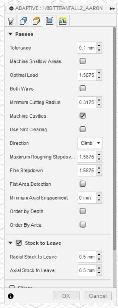
Thanks to their assistance, for the 1/16 in a bit instead of halving the value, I kept it the same because the bit was too small, and the projected time changed from 8 hours to 1 hours. Everything was set and after I created the two toolpaths for each bit, I was ready for post process.
Post Process
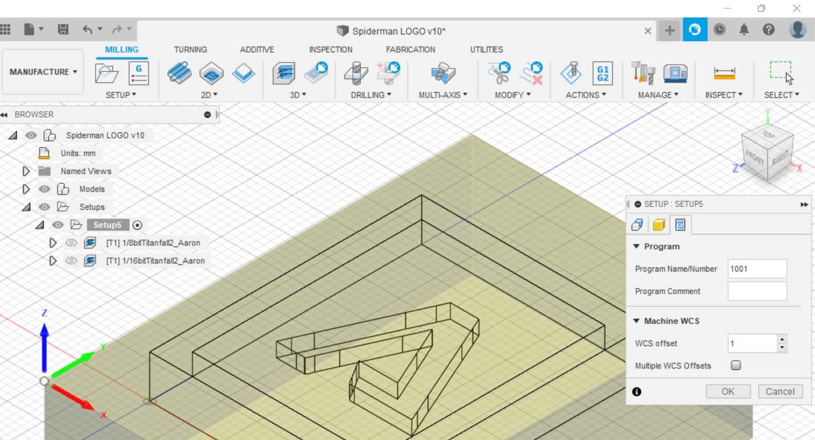
I downloaded the machine libraries for bantam tools using this documentation. I would have to create two GCode files for each bit. In the post process window, I changed the file name and made sure not to touch the file number (following advice from Charlie Horvath). I changed the file location and saved the toolpath but then I ran into this warning.
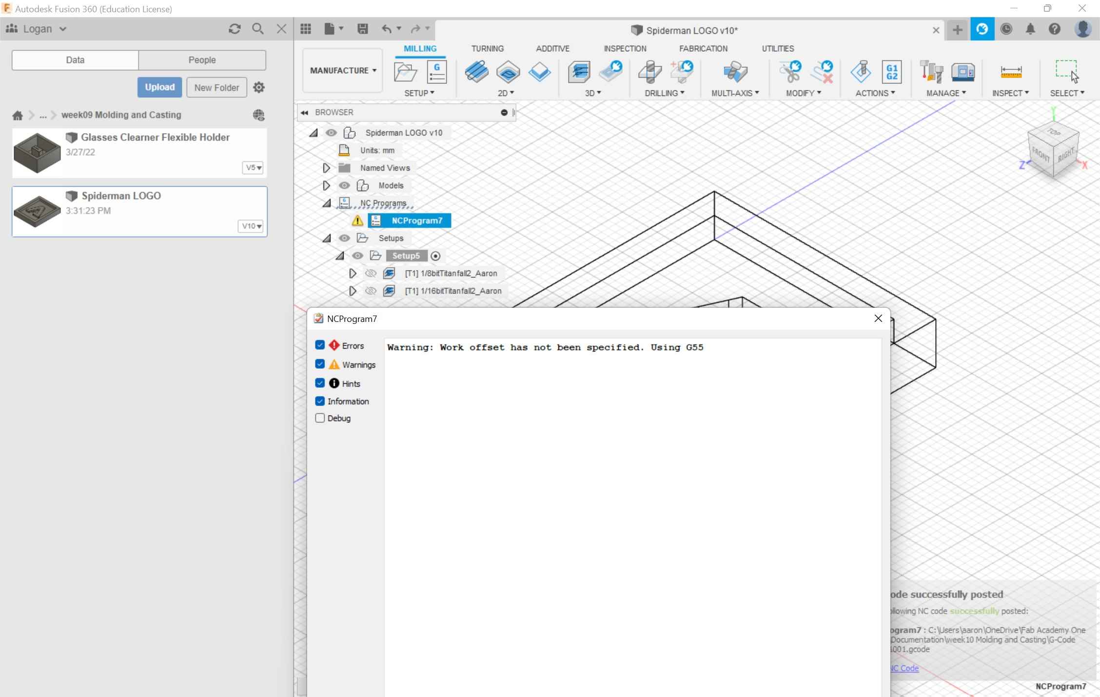
I initially thought it was my normal z-axis offset so I changed this value, and I still received the warning. I tried everything, changing the origin, adjusting the thickness of the stock, changing the optimal load, etc. I was still receiving the error. After going to this website, I realized that I had to go back into the setup and click on the post process tab and change the WSC offset from 0 to 1mm. The software predicted a 3-hour cut and according to everyone else present, this was normal.
Milling
I used my previous documentation on how to properly operate the machine. I saved the GCode files and loaded them into the Bantam tool’s software. I loaded up the rough pass file. Surprisingly the rough cut would only take 2 minutes. I realized that for the simulation, I selected a general Fusion 360 machine, and the time was based on this simulation and not the actual othermill. I didn’t have to probe the material thickness for the clay because the values I inputted into Fusion 360 passed over to Bantam tools. I did have to make a couple of edits. The values for the clay I was using were flipped and were off by 3mm. The file showed up horizontally while the Fusion 360 file was vertical. I had to change the thickness of the material. For some reason, it was set to 25.38mm instead of 17.18mm. I made this change, loaded the bit, and ran the rough cut.
I then loaded the finishing cut and the time was estimated at 4 minutes. I changed to the 1/16 in ball end bit. After this, I ran the finishing cut and my CAM was finished.
Retrospective
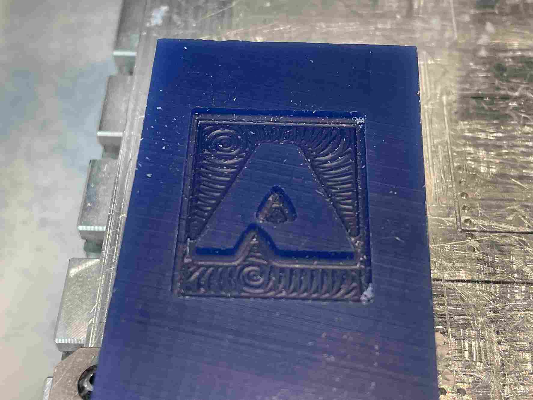
After I finished this weeks assignmnet I realized that their was a more effective way to perfom the finishing cut. The 3D adaptive tool that I selected was specifically made for roughing passes. After reading the documentaion I thought I could do the same process for the finishing pass by selecting 3D adaptive but their are many options that I skipped out on. Under the 2D section their are many different passes for specific situations like finishing a flat plane. Under the 3D section their were also different passes that delt with walls and curvature for the finishing. Using these tools, the bit would only mill around certain selected areas to help finish them off. Although, since I used the 3D adaptive tool path, it ran the EXACT same path as it would with a larger bit. This explains why the milling machine was milling out nothing for most of the cuts. This would also decrease the time of the cut by a large margin too.
If I were to mill out another mold I would use the 3D adaptive tool path for the inital roughing pass and select a flat end mill bit, which works better for clearing out flat surfaces. I would follow the documentation I have here for that. Then, for the finishing pass looking at the design I would select different 2D and 3D tool paths for finishing not the 3D adaptive tool path, to fit the cut that I am looking for, along with using a ball end mill. Again, I made an error in selecting the 3D adaptive tool path for my finishing pass. Due to this, the cut was the exact same and didn’t mill out anything, and also I was using a smaller bit which also lead to nothing being milled out. The image above for the final cut was the exact same as the clay after the roughing pass.
Revisions
Manufacturing
I decided to go back and redo the roughing and finishing pass for the titanfall 2 design, with the following changes.
- Roughing Pass: 1/8 in flat end mill bit. (3D adaptive)
Since I had already had a roughing pass set up, I could easily change the bit and re-generate the pass. Since The library for the Othermill was saved, I just selected the first roughing pass, then changed the bit from 1/8 in ball end mill to the 1/8 in flat end mill bit. I didn’t have to change any of the settings mentioned above because the diameter of the bits were the same. Using a flat end mill, the pass was a different and took out less material because it couldn’t pass throught the tight spots of the design.
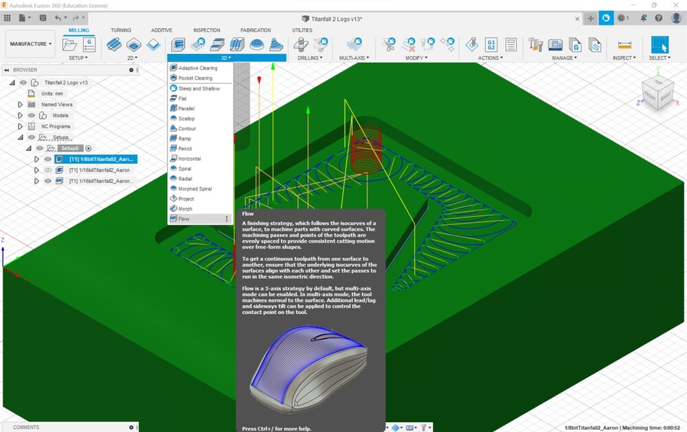
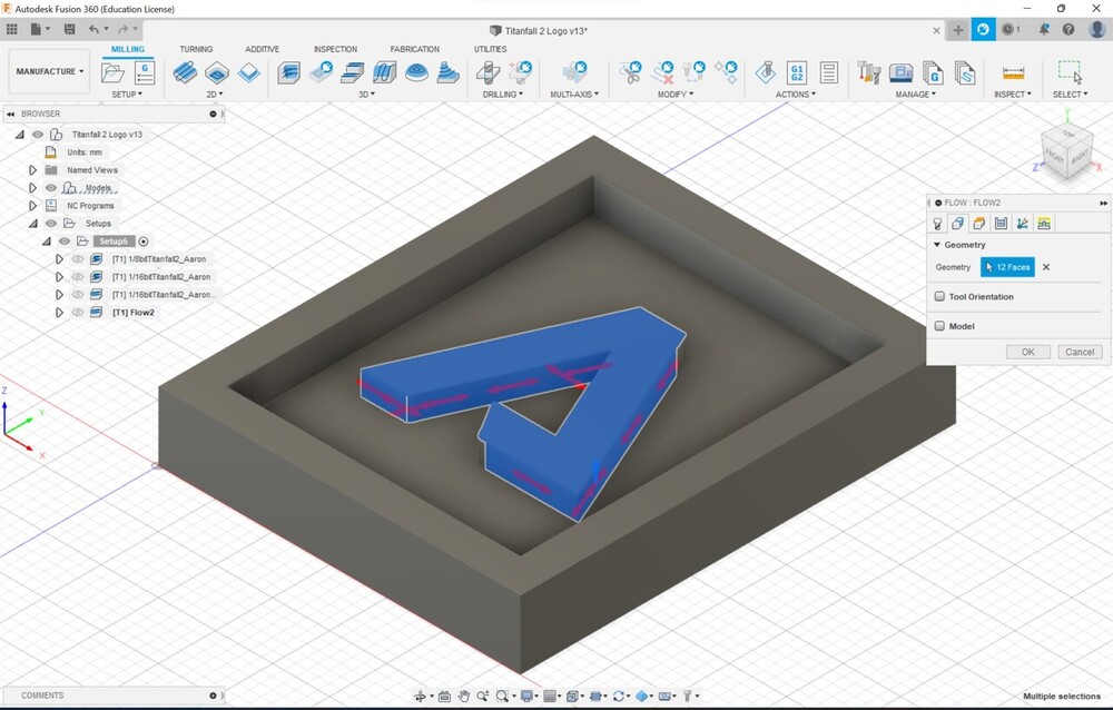
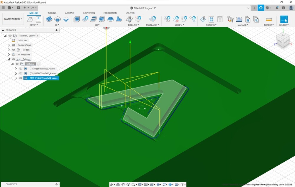
- Finishing Pass: 1/16 in ball end mill bit. (3D Flow Finishing)
I was looking for finishing passes in the 3D section to give a nice curved surface to the design and the Flow pass seemed like the best one for that. After selecting this pass, I was prompted to choose the different faces to finish. I selected all of the faces on the logo then clicked finish. Fusion 360 did all of the work after that and generated the pass. Comparing this pass to the my original finishing pass, it is clear the differences.
Milling
After I made the changes to the file, I followed the post process steps mentioned above. I put the file into bantam tools, then started the mill. This was the result of the roughing pass.
This was much more different than my original roughing pass with the ball end mill.
These were the results of the finishing pass.
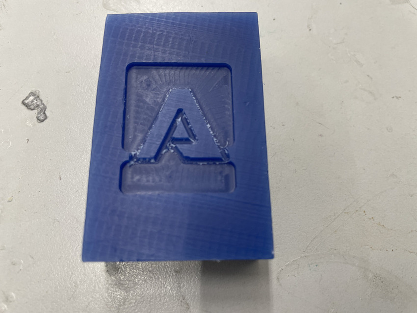
These results were much more different than my first time. The finishing pass was able to clear out much more of the clay than I originally thought possible. It is clear that using an actual finishing pass recommended in Fusion 360 is better than trying to salvage a 3D roughing pass. Also this results had curved edges, something that was intented in the actual design process. Unlike the first time, the curved edges were a result of the bit and not an actual finishing pass. This time, with an actual finishing pass, the curved edges that I designed, were milled.
Molding and Casting
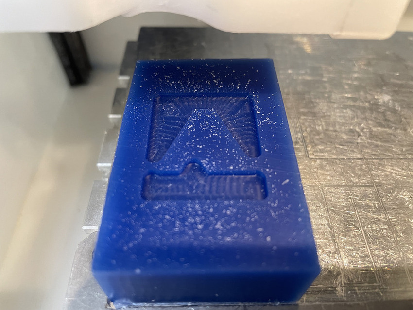
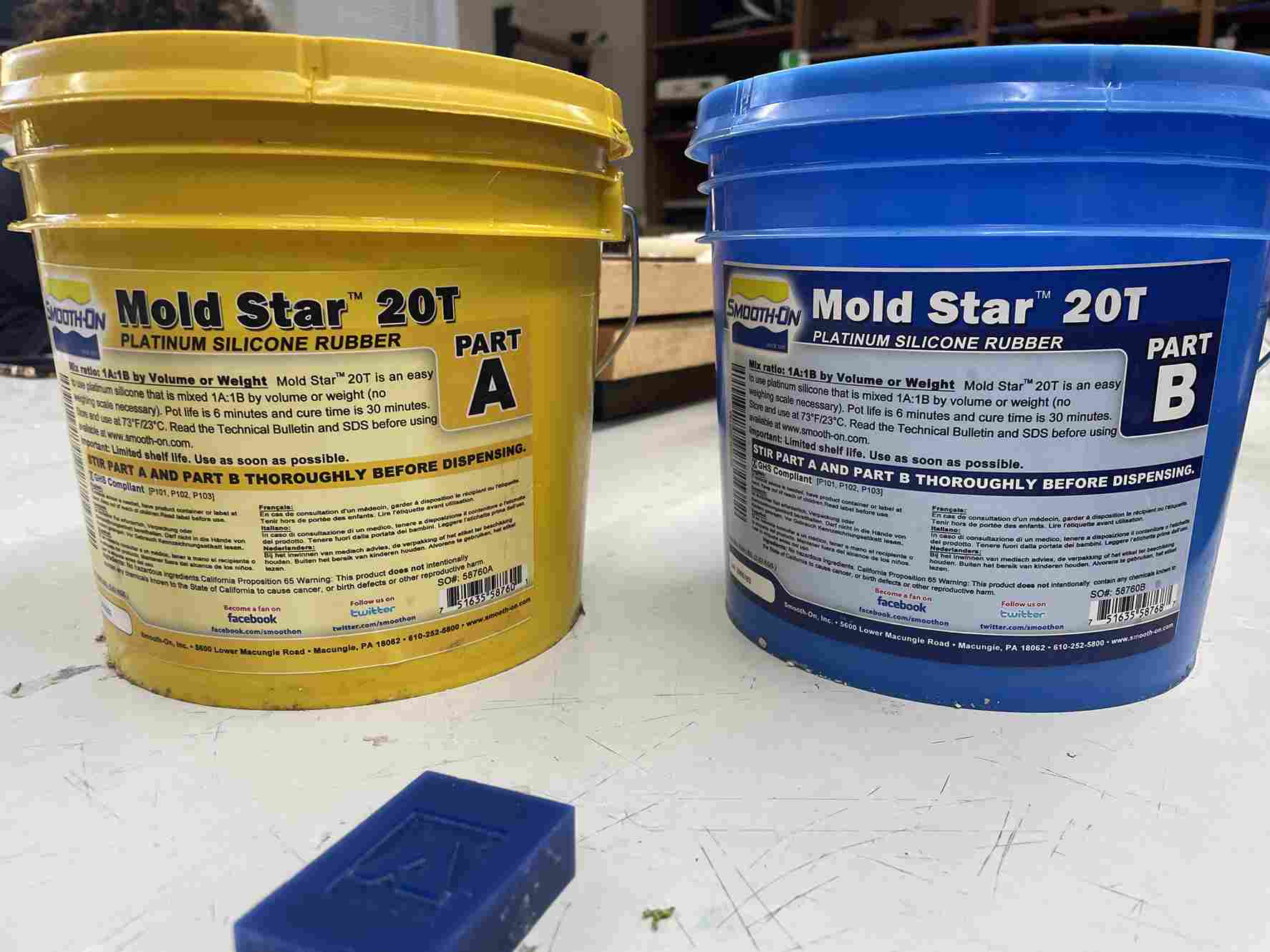
I grabbed a pair of gloves, two mixing sticks, and lots of cups before I began mixing. I wanted to create a hard logo, so I had to create a soft mold before casting. I used Mold Star 20T for the initial mold.
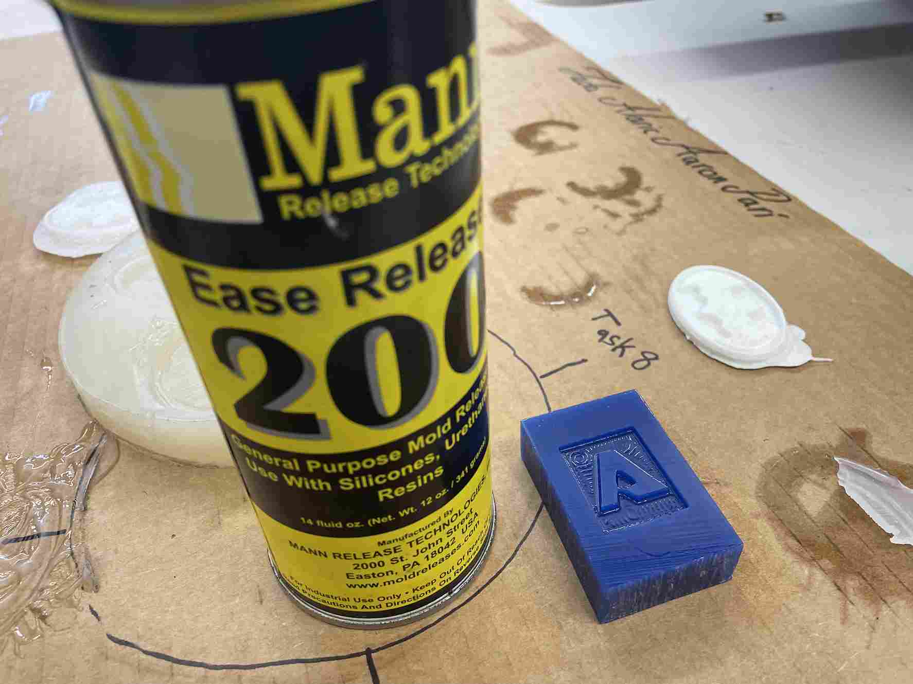
I sprayed the clay with ease release 200 so the removal process would be easy.
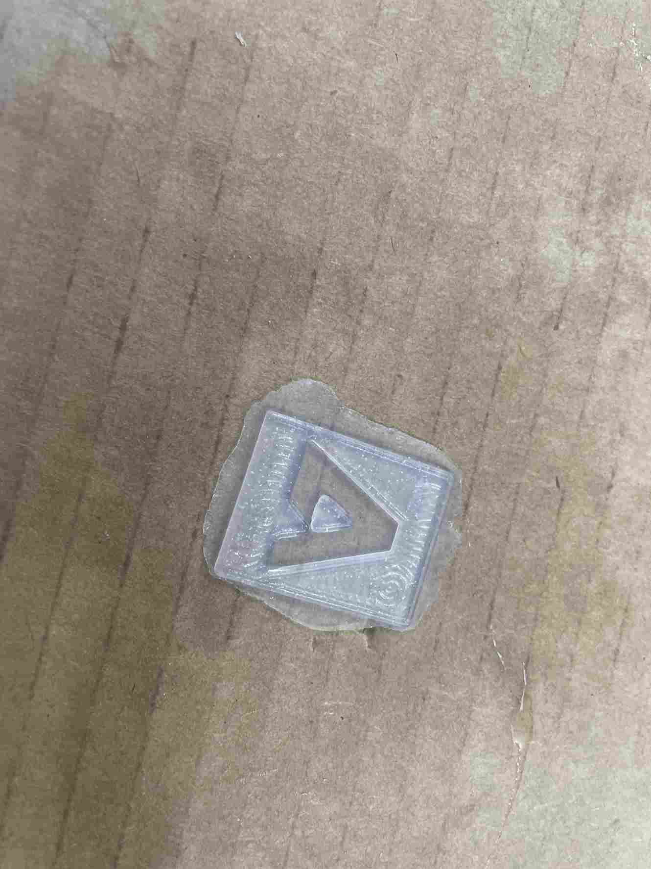
Looking at the Mold Star T Series Information Sheet, the ratio of 20T was 1:1 with a pot life of 6 minutes. I collected two cups and filled them with the same amount of mold. Since the depth of my cut was very thin, I had to be careful with the amount I would put in the cup; I was used to this process due to the group assignment. Since the pot life was 6 minutes, I had ample time to mix the mold and clear all the bubbles. I poured the mixture into the clay, and it was the perfect amount. After 45 minutes I went back to check, and everything came out clean. My only regret is that I didn’t make the depth cut a little bit larger because the final product was extremely thin. Adding to the fact that the mold was flexible, I had to be careful with the next step.
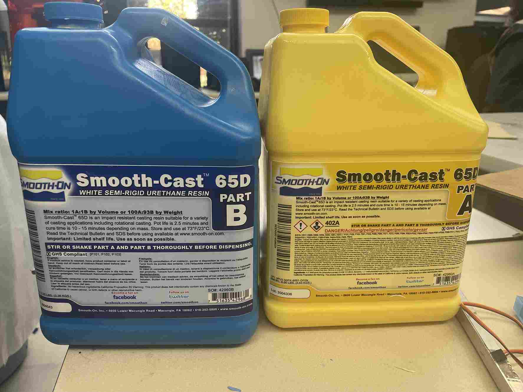
For the hard cast, I used Smooth-Cast 65D. I found the Information Sheet and looked at 65D and found that the ratio was still 1:1 but the pot life was 2.5 minutes, so I had to be quick with the mixing process. I used the same workflow mentioned earlier in terms of mixing and preparation.
I had to collect an even smaller amount than before with the Mold Star 20T, so the mold didn’t overflow. The Smooth-Cast 65D was had more waterlike properties so the collecting and mixing were easier than the Mold Star 20T. I poured the mixture in and waited another 45 minutes even though the cure time was 10-15 minutes.
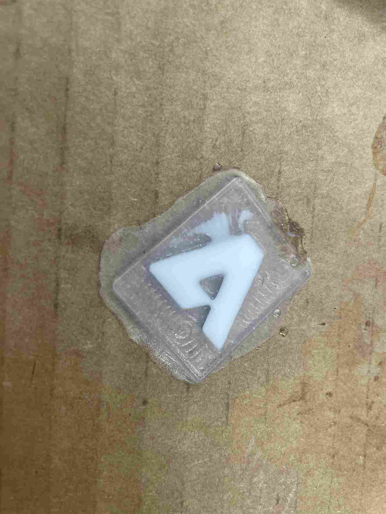
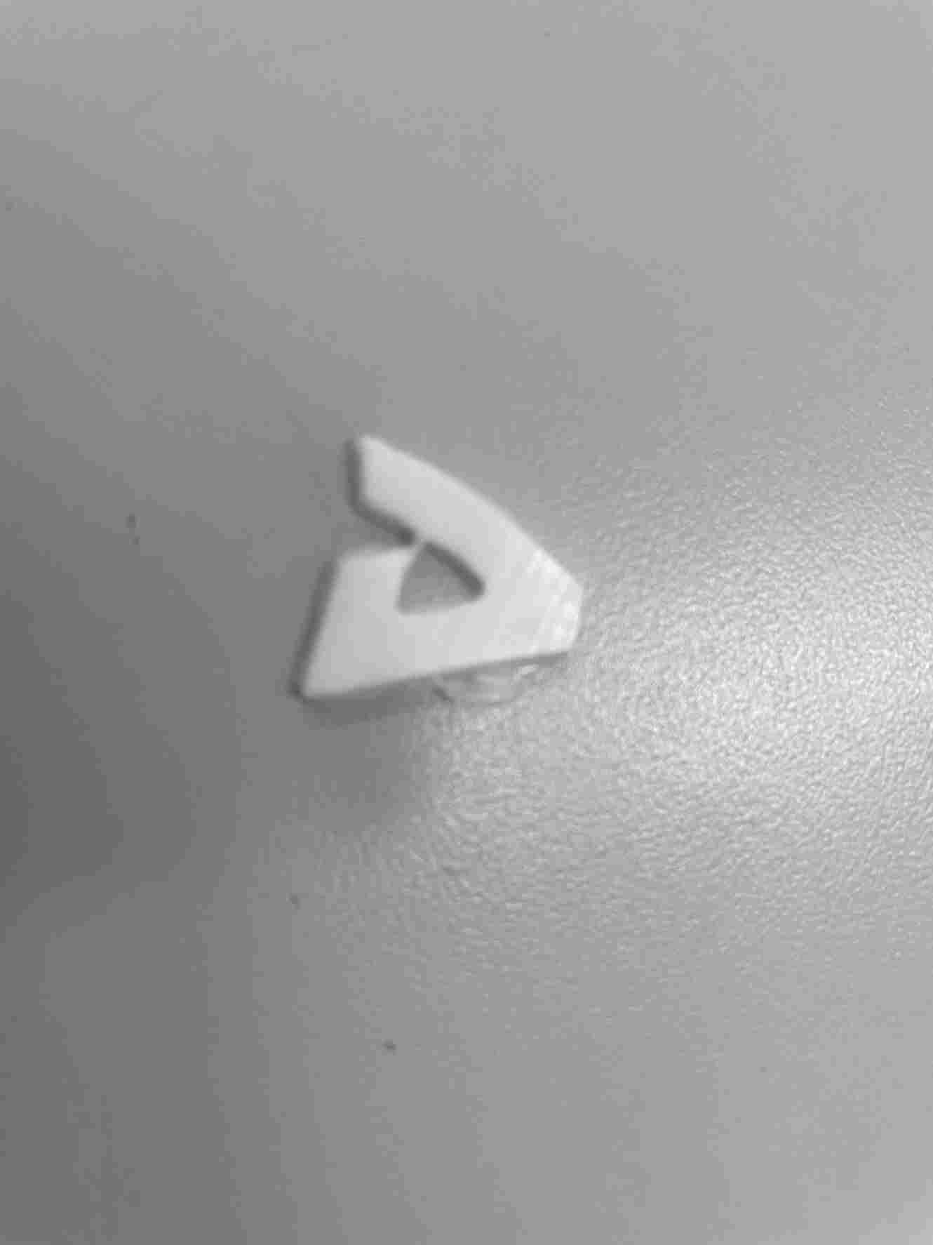
I pullout out the logo and I had successfully molded my Titanfall 2 logo.
Problems I Ran Into
- Creating designs that were too small or had sections that were too small for the bit to mill out
- Not creating a tray for the resin to pour for my first couple of designs
- Creating a shell selecting both faces which causes the design to have two bodies.
- Inputting values for the optimal load and maximum roughing stepover as half the diameter of a 1/16 in ball end mill
- Not changing the value of fine stepdown so that it was the same as the optimal load and maximum roughing stepover
- Not changing the WSC Offset value so I wouldn’t receive the warning
- Making the cut depth smaller than anticipated
- Having to change the dimensions on the Bantam software
What I Learned
I’ve been using Fusion 360 for about 2 years, but I’ve only used the design section and just exported STL files for my 3D printer. I never knew Fusion 360 had so many different applications. I’ve also milled before, normally circuit boards and key chains, but never a large object. I didn’t even know I could use a ball end bit on a small milling machine. Normally when I use the othermill everything seems structured. During previous weeks, I’ve only had to change the bits and the trace clearance and depth, otherwise, the computer handled the rest. This week I felt like I had more control over what I wanted the machine to do. There were many options under the manufacturing tab of Fusion 360 that I didn’t even look at, such as the 2D milling, or the parallel toolpaths. I also realized that I could use this for 3D printing because there was a section labeled under operation that I could change to additive. This week felt like I was controlling the machine compared to just operating it.
Group Assignment
This week’s group assignment was to compare different casts and review the safety data sheet for each of the materials. For my group, group A2, I assisted in collecting, mixing, pouring, and extracting the molds, specifically, Mold Star 31T, Smooth Cast 65D. I learned about what each mold would produce, whether it was a flexible or rigid mold. This data helped determine what molds to use for this week’s assignment. The site is located here.
Files
- The tool libraries I mentioned earlier are located here.
- My working Titanfall 2 file is located here