14. Networking and Communications
Assignment: Design, build, and connect wired or wireless node(s) with network or bus addresses
Research
I wanted to encoporate all of my previoius boards. So when I use the RFID card, the DC motor should begin to rotate, which will be exactly what I use for my final project. I began doing some research on different ways to communicate and which ones would be better. I already had some background knowledge from input week using I2C for my OLED screen and SPI for my RFID reader. I came across these sites and Youtube Videos on I2C communication and I decided that I was going to use that.
I had experince using that, and it only requires 2 wires and the wire library for an arduino. I would run into one issue, the OLED requires I2C communication however, I need those pins for Master and studnet board communication. Their are alternate pins on the microcontroller that allows me to use I2C on PA2 and PA1
For this weeks assignment I will only focus on the RFID and the DC motors.
KiCad
I would have to create two new boards. The first one would act as the master while the second one would be the student DC motor board.
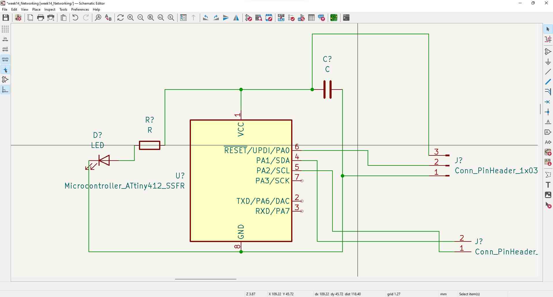
Schematic Master
I would use a ATTiny412 microcontroller for this board because I only needed the SDA and SCL pins for the bus while also needing the TX and RX for serial communication. I simply added a couple of headers for pins mentioned earlier, then a 3 pin header for the power, ground and UPDI. Similarly to my previous boards, I included a power LED to check if it was recieving power. The final results are below.
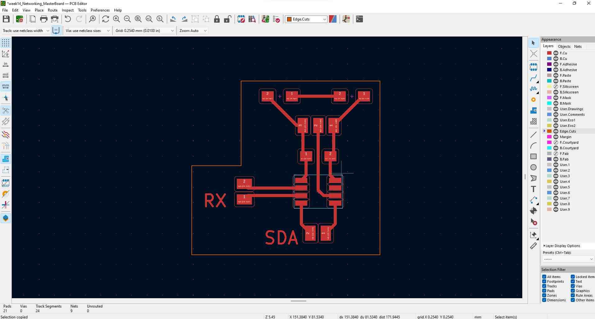
Editor Master
Using my previous documetntation I was able to connect the traces easily.
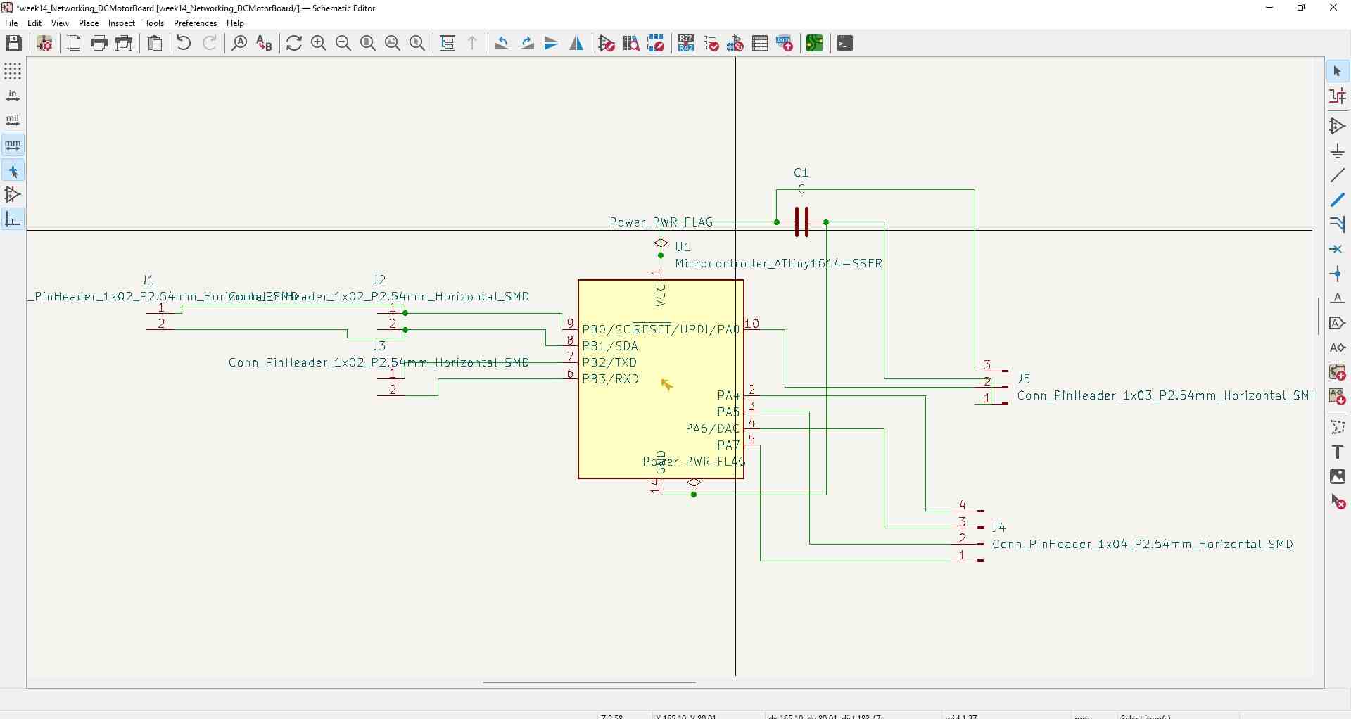
Schematic Student DC Motor
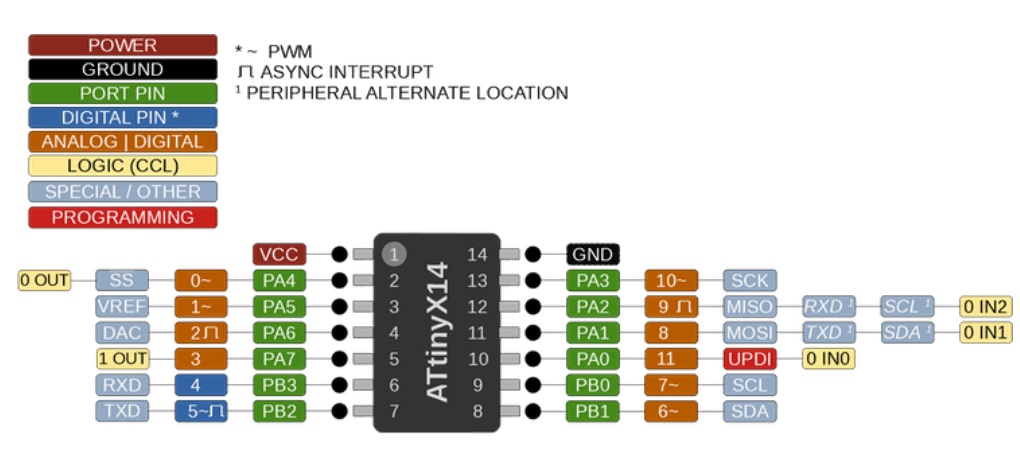
This was a little more complicated. Getting the capacitor, LED, resistor, and 3 pin header was the easy part. However, looking back at my output week I needed analog pins to be connected to the header for the motor driver I was using. The ATTiny1614 only had a limited amount of analog pins that I could use. Some of the pins were the TX, RX, SDA, and SCL pins. I wanted to keep the 4 pin header that would control both motors on the same side, therefore I had to use the left side of the microcontroller (refering to the pinout image above). The two analog pins were next to each other, so I had to alternate the pins. PA4 (analog pin) connected with PA6, and PA5 (analog pin) connected with PA7. This way the wiring would be more direct. I also had to connect a pair of 2 pin headers to the SDA and SCL pins for the bus to work. The final schematic is below.
Editor Student DC Motor
As I mentioned earlier, I used my previous documentation to connect the traces, but because the motor pins had to alternate I had to run a trace through the microcontroller. Other than that, the rest of the connecting was simple. My final design is below.
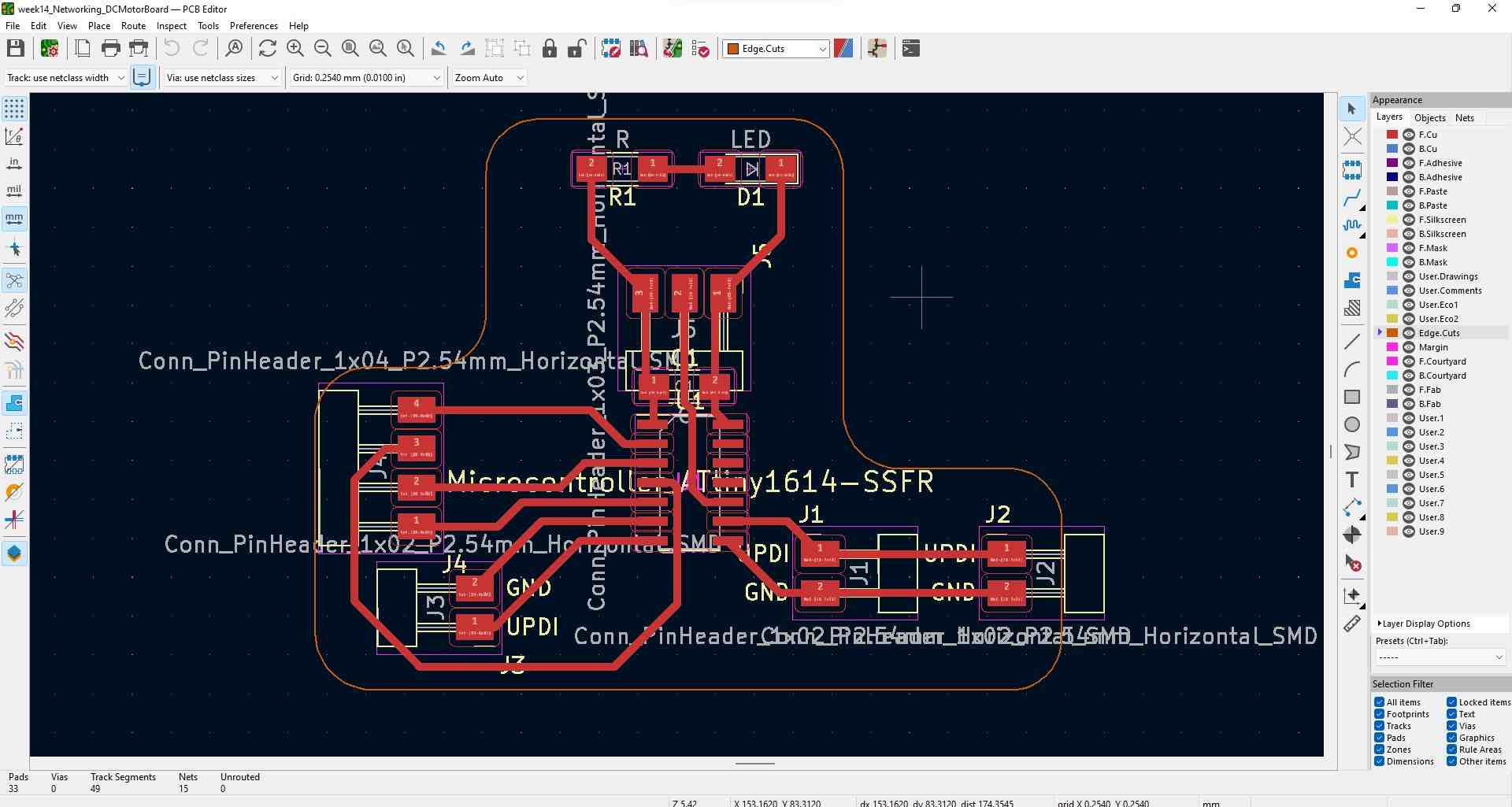
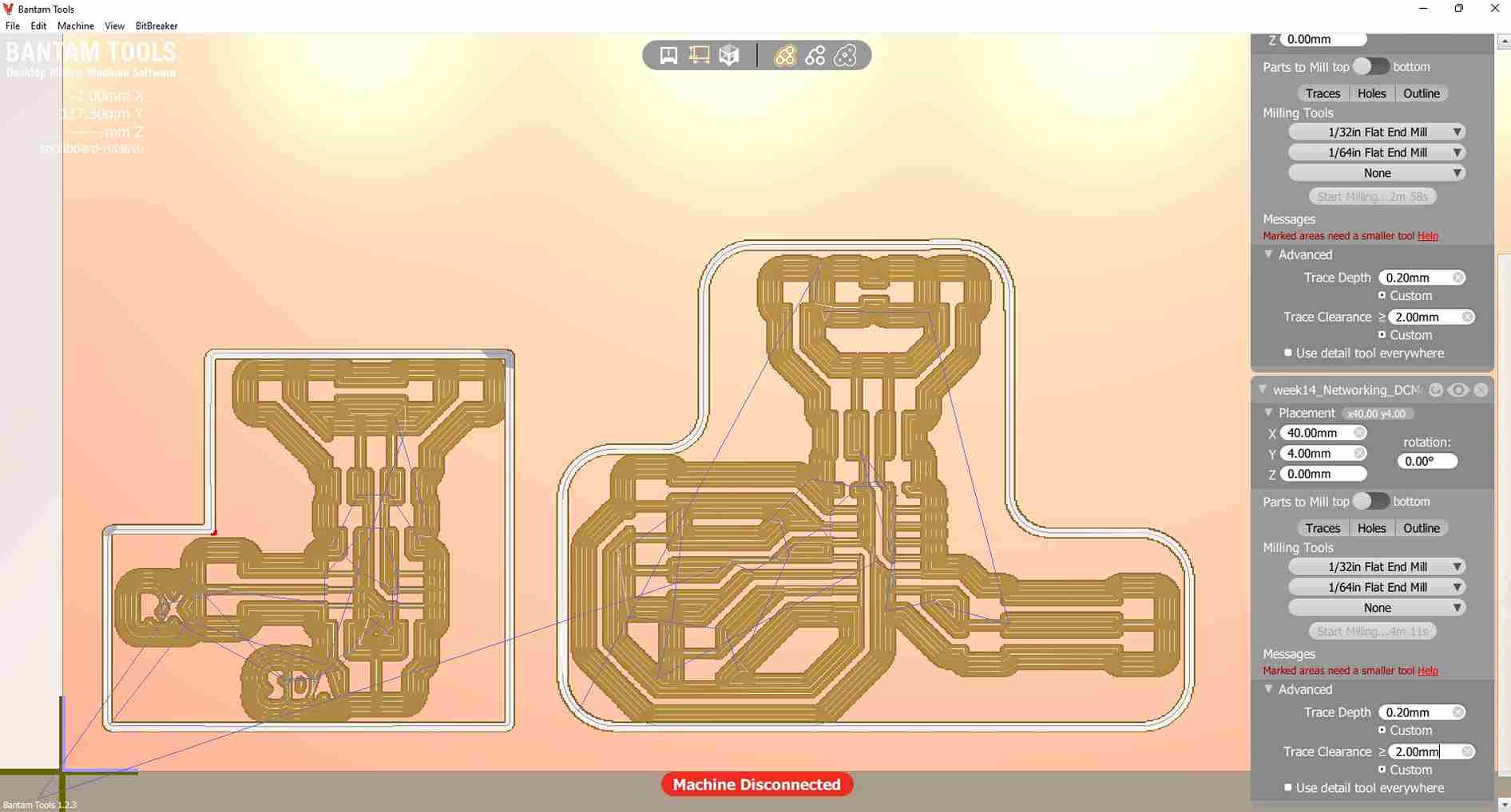
I generated the F.Cut and Edge.Cut file then exported that to Bantam Tools.
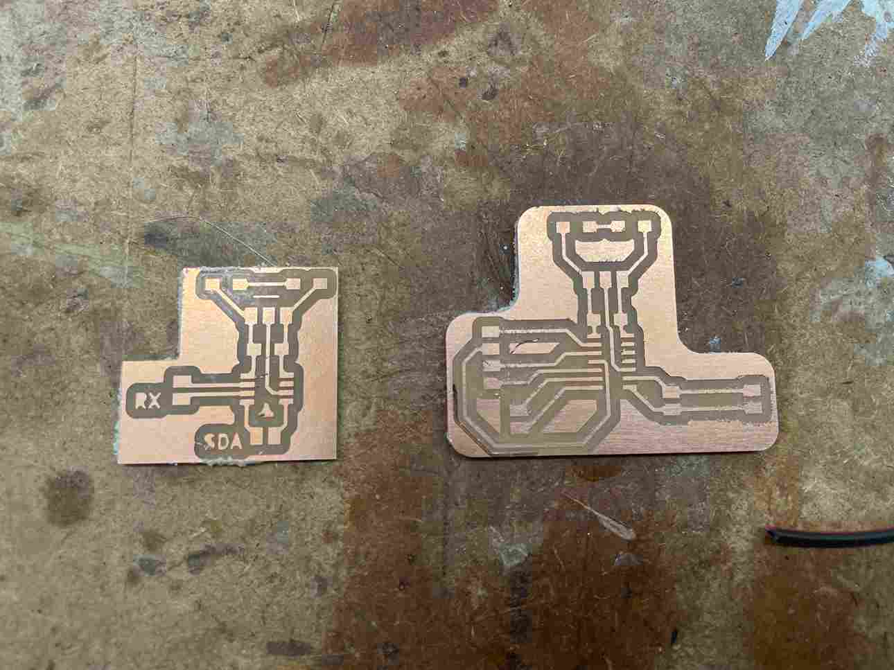
Milling
I used my earlier documentation to mill the boards. Here are the results
Programming
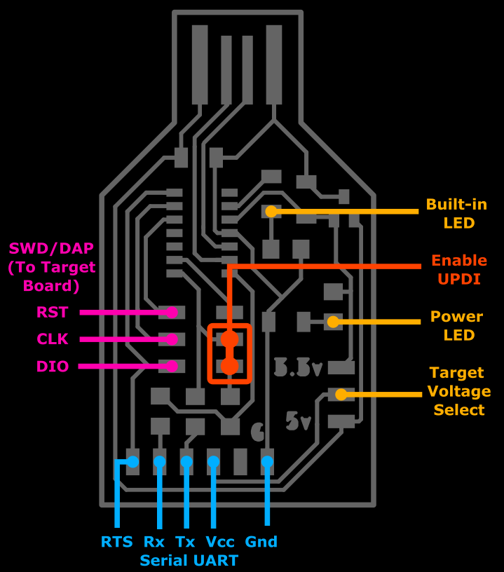
Converting Programmer To FTDI
Using my earlier documentation, I had to convert my programmer into a FTDI reader because I had to make sure the data I was transmitting from the student board was being recived from the master board. The code I used to convert it is below.
void setup() {

   SerialUSB.begin(0);
   Serial1.begin(9600); //Adjust baud rate and use SERIAL_8N1 for regular serial port usage
}

void loop() {
   if (SerialUSB.available()) {
      Serial1.write((char) SerialUSB.read()); //Send stuff from Serial port to USB
   }
   if (Serial1.available()) {
      SerialUSB.write((char) Serial1.read()); //Send stuff from USB to serial port
   }
} //end loop
Using the pinout I connected the TX of the board to the RX of the programmer, then similarly the RX of the board to the TX of the programmer.
ATTiny1614 Struggles
I initally started out with an plan of using my RFID card to control my DC motor using my input week and my output week documentation. My first error was that I was trying to use a library that I didn’t understand, while also trying to code everything at once. My hardware was correct, though it was my coding that would keep me working for hours. For I2C communication I had to use the Wire Library. Thankfully the Arduino IDE already has this downloaded for use. I had to use the line #include <Wire.h> at hte beginning of my code. The links below were extremely helpful in understanding how the library worked.
I wanted my network to function so when I the RFID card was read on the student board, it would send a signal to the master board to move my motor, so I began with the student board. I didn’t test my code with a normal Arduino and went right into coding for the ATTiiny1614. I went to instructables.com to get some example code. I didn’t understand a lot of the functions at first, and was configuring the code until something popped up. I soon realized that trying to connect everything at once would be too tall of a task so I decided to simplify it by only having two microcontrollers communicate with each other.
I did learn that the wire librarys power comes from these three functions and to transfer data from the master I would have to include these functions.
 Wire.beginTransmission(4); // transmit to device #4
  Wire.write(x);             // sends x
  Wire.endTransmission(); // stop transmitting
After again working for hours on trying to test code, then reading the serial port, then test again. I came up with this code for the master and student board.
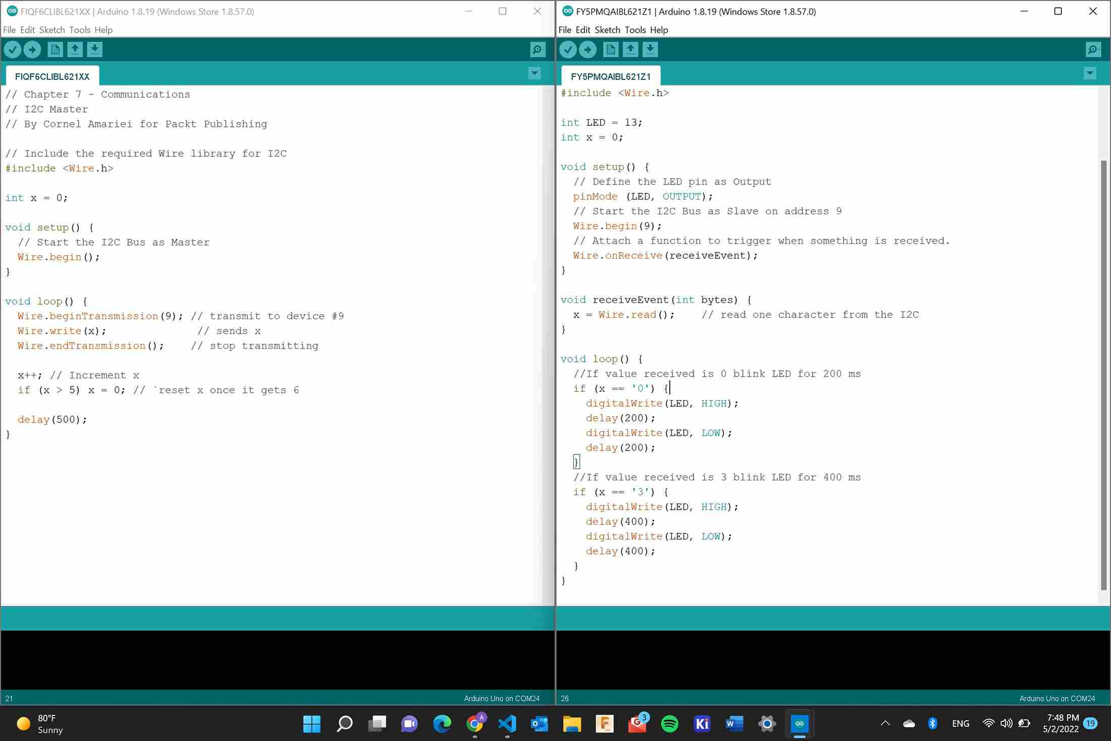
My idea behind it was that the master board would send an integer x. The integer would increase from 0 to 6 then reset back to one. I made it so an LED would flash with a signal coming from the student board if the number recived was either a 0 or 3. In regards to the boards I milled, I realized that I had to use my new studnt board and my old input board because they could share a common ground easily. The code I typed up didn’t work and what I soon realized after two things that I did wrong. One is that I wasn’t understanding exactly what type of data I was sending. Two is that I wasn’t using the Wire.avalible function to read the code. I learned that the Wire.avalible works with the Wire.read function to store the data being recieved into a char or int if both funcitons are in a while structure. This was structre that I used
{
  while (0 < Wire.available())
  {
    x = Wire.read();
    Serial.print(x);
  }
}
I recommend going to the Arduino.com Documentation mentioned earlier and Arduinos example I2C documentation for a better understanding of how the functions and I2C works. Due to this I also learned that I had to create a function that the Wire.onReceive(); function could run once it recieved data from the master.
Knowing that adding in the two functions mentioned above would fix the code, I then tried to encoporate my RFID ID into the code because that is what I would be doing for my final project. I created a simple string 128 45 to try and transfer from the master to the student. I ran into a bunch of errors regarding the conversion between strings and characters/integers. I tried to change the data type I was sending from an int to a string and stored it in variable x but this wasn’t working becuase I still couldn’t use the variable. I tried for hours and came to the conclusion that I had to get all of my networking functioning on an arduino before I could try my boards.
Going Back To Arduino
I still tried to use the same code as ealier to light the LED. I tried to transfer the string using the Wire.write(); but I still ran into some errors with data types. Dr. Harris helped me realize that I needed to use Wire.print(); to transfer strings. I made this change along with using the Wire.avalible and Wire.read. After making this change I was able to recieve the string from the master board in the student terminal. For information on different types of data I used the links below.
I tired to use the string to light and LED and it worked.
Thought their was some issues that I found through some testing. I made the master send another string that was 44. I then coded the student board to turn off if the string it recieved wasn’t 128 44 and I found out that the LED would stay on regardless of the string. I still ended up trying to troubleshoot this and I decided to restart. I would work on basic serial communication first then work my way up back to this point later.
I followed Arduinos example I2C documentation again but this time I was only using Arduinos to start off as. Following the site was easy and I was able to get the Arduinos to communicate. Similar to my ATTiny1614 struggles, I wanted to send the string ID number 128 44 from the master arduino to the student arduino. Since I was used to this I was able to get the boards to communicate the string. Now I was back to where I was originally with the ATTiny1614 and Arduino, trying to get the string to store in a number. Again I wasn’t able to get the string to translate into lighing a LED. I was recieving it in the serial port but I couldn’t use it. I went and searched up ways to convert string to char arrays or how to compare two different strings but this didn’t work either. This was the site I went to.
I then had a better idea. I was using a string becasue that is what my RFID card stores. Looking at my week 11 final code I was able to configure it so if the string in the loop matched the ID then it could perform functions. I could make it so the RFID card only sends 1 integer or byte of information when the card ID number is the right ID using the RFID and SPI library. With this in mind I wanted to see if I could first send integers before progressing to the RFID ID number. It was simple to send one integer using instructables documentation. I had to make sure to change the byte x = 1 to int x = 1. After configuring this, I sent the integer I wanted. I then wanted to send a second integer with the same concept as earlier, where the LED would turn off if the information it read was inaccurate to the condition. I typed this code to transmit both integers, with x = 1 and y = 0.
Wire.beginTransmission(4); // transmit to device #4
  Wire.print(x);             // sends five bytes
  delay(1000);
  Wire.write(y);
  Wire.endTransmission(); // stop transmitting
Before typing any code to use the incoming data I checked the serial terminal of the student arduino and realized that the data was coming in too fast. I was confused at first then I thought back to what cesar anco jove said, The data is only transmitted after it is all gathered. Even with the delay function there it wouldn’t do anything. So I went back to the master arduino I split the transmission into 2 different parts, one sending the x variable with a delay, then the other sending the y variable with a delay. This was the code used
  Wire.beginTransmission(4); // transmit to device #4
  Wire.print(x);             // sends five bytes
  delay(1000);
  Wire.endTransmission(); // stop transmitting
  Serial.print("0 sent");
  Wire.beginTransmission(4); // trasmit to device #4
  Wire.print(y);             // sends the 1 byte
  delay(1000);
  Wire.endTransmission(); // stop transmitting
  Serial.print("1 sent");
With this I was getting consistent readings from the serial terminal. I added one more variable “z” to make sure and it worked properly. I then configured that with the LED code from instructables.com and the LED worked. The final code for lighting the LED is below.
Master Code
int x = 0;
int y = 1;
int z = 2;

#include <Wire.h>

void setup()
{
  Wire.begin(); // join i2c bus (address optional for master)-
}

void loop()
{
  Wire.beginTransmission(4); // transmit to device #4
  Wire.print(x);             // sends five bytes
  delay(1000);
  Wire.endTransmission(); // stop transmitting

  Wire.beginTransmission(4); // trasmit to device #4
  Wire.print(y);             // sends the 1 byte
  delay(1000);
  Wire.endTransmission(); // stop transmitting

  Wire.beginTransmission(4); // begin transmission to device #4
  Wire.print(z);             // sends 2 bytes written
  delay(1000);
  Wire.endTransmission(); // stop transmitting
}
Student code
#include <Wire.h>
#include <stdio.h>
#include <string.h>

void setup()
{
    pinMode(6, OUTPUT);
    Wire.begin(4);                 // join i2c bus with address #4
    Wire.onReceive(motorFunction); // register event
    Serial.begin(9600);            // start serial for output
}

void loop()
{
    delay(1000);
}

// function that executes whenever data is received from master
// this function is registered as an event, see setup()
void motorFunction()
{
    while (0 < Wire.available())
    {
        char x = Wire.read();
        Serial.print(x);
    }
    int x = Wire.read();
    if (x == 0)
    {
        digitalWrite(6, HIGH); // Lights LED
    }
    else
    {
        digitalWrite(6, LOW); // LED turns off
    }
}
ATTiny1614 Working
The next step was to go back to the ATTiny1614 boards and get them to work. I used the code ealier as a base line for how I wanted to function the microcontrollers. When configuring the code the only edit I had to make was to turn on the internal pullup resistors. Arduinos clearly automatically pull up the resistors because I never had to configure that, but I did for the microcontrollers. I referenced my embedded programming documentation on how to use that. I also referenced the ATTiny1614 datasheet page 133 to make sure the pins were correct and register I was editing was correct.
I had to type these two lines of code into the void setup()
PORTB_PIN0CTRL |= PORT_PULLUPEN_bm ;
PORTB_PIN1CTRL |= PORT_PULLUPEN_bm;
After typing this I was reciving the integers from the master board into the student board. I then rewrote the LED code for the microcontroller and it worked. The code is below
Master Attiny1614
int x = 0;
int y = 1;
int z = 2;

#include <Wire.h>

void setup()
{
  Wire.begin(); // join i2c bus (address optional for master)-
  Serial.begin(9600);
  PORTB_PIN0CTRL |= PORT_PULLUPEN_bm ;
  PORTB_PIN1CTRL |= PORT_PULLUPEN_bm;
}

void loop()
{
  Wire.beginTransmission(4); // transmit to device #4
  Wire.print(x);             // sends five bytes
  delay(1000);
  Wire.endTransmission(); // stop transmitting

  Wire.beginTransmission(4); // trasmit to device #4
  Wire.print(y);             // sends the 1 byte
  delay(1000);
  Wire.endTransmission(); // stop transmitting

  Wire.beginTransmission(4); // begin transmission to device #4
  Wire.write(z);             // sends 2 bytes written
  delay(1000);
  Wire.endTransmission(); // stop transmitting
}
Student ATTiny1614
// Wire Peripheral Receiver
// by Nicholas Zambetti <http://www.zambetti.com>

// Demonstrates use of the Wire library
// Receives data as an I2C/TWI Peripheral device
// Refer to the "Wire Master Writer" example for use with this

// Created 29 March 2006

// This example code is in the public domain.

#include <Wire.h>
#include <stdio.h>
#include <string.h>
int x = 0;

void setup()
{
  pinMode(3, OUTPUT);
  Wire.begin(4);                 // join i2c bus with address #4
  Wire.onReceive(motorFunction); // register event
  Serial.begin(9600);            // start serial for output
  PORTB_PIN0CTRL |= PORT_PULLUPEN_bm ;
  PORTB_PIN1CTRL |= PORT_PULLUPEN_bm;
}

void loop()
{
  delay(1000);
}

// function that executes whenever data is received from master
// this function is registered as an event, see setup()
void motorFunction()
{
  while (0 < Wire.available())
  {
    x = Wire.read();
    Serial.print(x);
  }
  if ( x == 0)
  {
    digitalWrite(3, HIGH); // Lights LED
  }
  else
  {
    digitalWrite(3, LOW); // LED turns off
  }
}
RFID with ATTiny1614 Networking
With everything mentioned before done I challeged myself to complete my one of my first goals, get the RFID to network a signal to another board to light an LED. I referenced my input documentation on coding. The wiring was the same becuase I was using my input board. After that I created a fucntion for the master transmission and put that into an if statement that would read the RFID number. Similar to last time if the RFID number was the same as the string specefied ealier then it would run the function, and in this case, transmit the data. I didn’t have to change anything for the student board because it was only reciving the integers and lighting the LED. On the master board I used the RFID if statment from my earlier week and used the transmission fuction as the code to run if the condition was true. The code is below for the master board
// Wire Master Writer
// by Nicholas Zambetti <http://www.zambetti.com>

// Demonstrates use of the Wire library
// Writes data to an I2C/TWI Peripheral device
// Refer to the "Wire Peripheral Receiver" example for use with this

// Created 29 March 2006

// This example code is in the public domain.

int x = 0;
int y = 1;
int z = 2;

#include <Wire.h>
#include <SPI.h>
#include <RFID.h>
#define SS_PIN 0
#define RST_PIN 1
RFID rfid(SS_PIN, RST_PIN);

String rfidCard;

void setup()
{
  Wire.begin(); // join i2c bus (address optional for master)
  Serial.begin(9600);
  SPI.begin();
  rfid.init();
  PORTB_PIN0CTRL |= PORT_PULLUPEN_bm ;
  PORTB_PIN1CTRL |= PORT_PULLUPEN_bm;
}

void loop()
{
 if (rfid.isCard()) {
    if (rfid.readCardSerial()) {
      rfidCard = String(rfid.serNum[0]) + " " + String(rfid.serNum[1]) + " " + String(rfid.serNum[2]) + " " + String(rfid.serNum[3]);
      if (rfidCard == "124 98 66 24") {
      LEDfunc();
      }
      else
      {
      digitalWrite(2, HIGH);
      }
    }
    rfid.halt();
  }
}


void LEDfunc()
{
  Wire.beginTransmission(4); // transmit to device #4
  Wire.write(x);             // sends five bytes
  delay(1000);
  Wire.endTransmission(); // stop transmitting
  Serial.print("0 sent");
  Wire.beginTransmission(4); // trasmit to device #4
  Wire.write(y);             // sends the 1 byte
  delay(1000);
  Wire.endTransmission(); // stop transmitting
  Serial.print("1 sent");
}
Revisions
I later realized during my final project that to use a condition or function that uses the data being transmitted, the function has to be within the while loop containing with wire.Avaliable function. When I use a while loop with the wire.Avaliable function, the function within the loop will continue even if data isn’t being transmitted. Though if I pair a if statement with the wire.Avaliable function, then the functions within the statement will only go on, if data is being transmitted. I’m not exactly sure how I got it to work this week but when I tried to use it for my final project I had to make these adjustments. For example my code looked like this,
.
.
.
while (wire.Avaliable()){
  int var = wire.Read()

  if(var == 1){
    example code
  }
}
With this example, the function runs forever once the condition is met, regarless if data is being transmitted.
Problems I Ran Into
- Not understanding what type of data I was sending for the Wire.read
- Not turning on pullup resistors
- Not understanding how the wire library functions work
- Not using Wire.avalible and Wire.read initially
- Using the wrong ports for the internal pullup resistor
- Using Wire.read for a string, but it sends integers and characters, then not Wire.print is used for strings
- Trying to program everything at once
- Not taking into account the RFID takes different voltage from the motor driver and having to use a LED instead
What I learned
This week was probably the most difficult one because I wanted to do everything at once. I started with the goal of trying to get my RFID to work with my DC motor without understanding exactly how to network. Throught this week I learned that their are different types of Networking and communications, the ones that I learned thorugh this week were SPI, I2C and Serial Multidrop. Using I2C, I realized the strength of the TWI. If I assign each node an ID, I can communicate with everything connected on the bus even if . I also realized the importance of having pullup resistors for the microcontroller. I finally understood what the wire library does. When Dr.Harris explained that it allows for easy I2C communication, I didn’t truly understand what he was saying until this week.
Group Assignment
This weeks group assignment was to network different projects of students. I worked with Barbara Morrow and Nidhie Dhiman on networking our projects using I2C communication. My board was one that worked compared to Nidhie’s. The link to the group site is located here