Final Project: Automatic Glasses Cleaner
Preliminary Questions
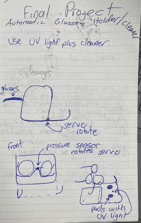
What Will it Do?
My glasses cleaner will clean the lenses of the glasses using a microfiber cloth that rotates around the lenses. Then a UVC LED will sterilize the frames of the glasses. The cleaner will be activated my an RFID card and an OLED display will be used to see how much time is left before the cleaner stops.
Whose Done It Before?
I searched the internet for a completed product but I only found a prototyped idea by LensHD. As I did more research on glasses and how to clean them, I found that there are two ways
Prototyping
This was my first design
This model was bad for two reasons:
- The frames are sticking out; the UV light won’t kill all the bacteria
- The UV light coming from the cleaner can be harmful to people
I designed a second model and this fixes the problem.
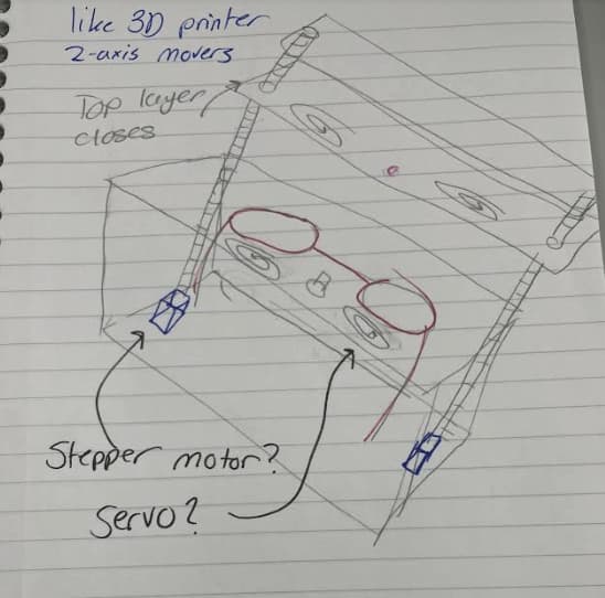
Again their was still room for simplification. Looking back at LensHD’s design, the only motor function that their design used would be two servos or DC motors. I went back to talk with Dr. Fagan and he also recomended to remove the stepper motors
Final Design
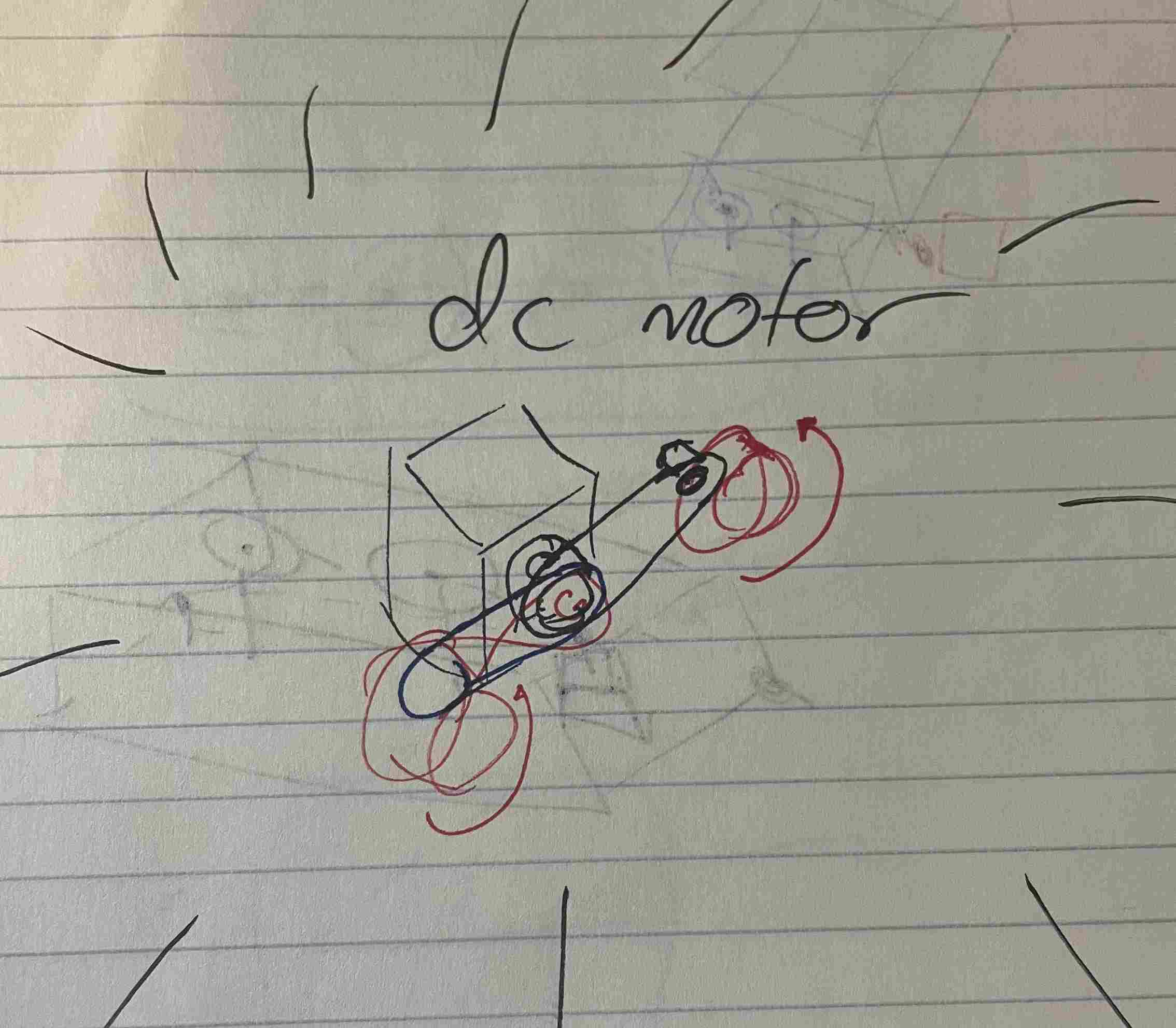
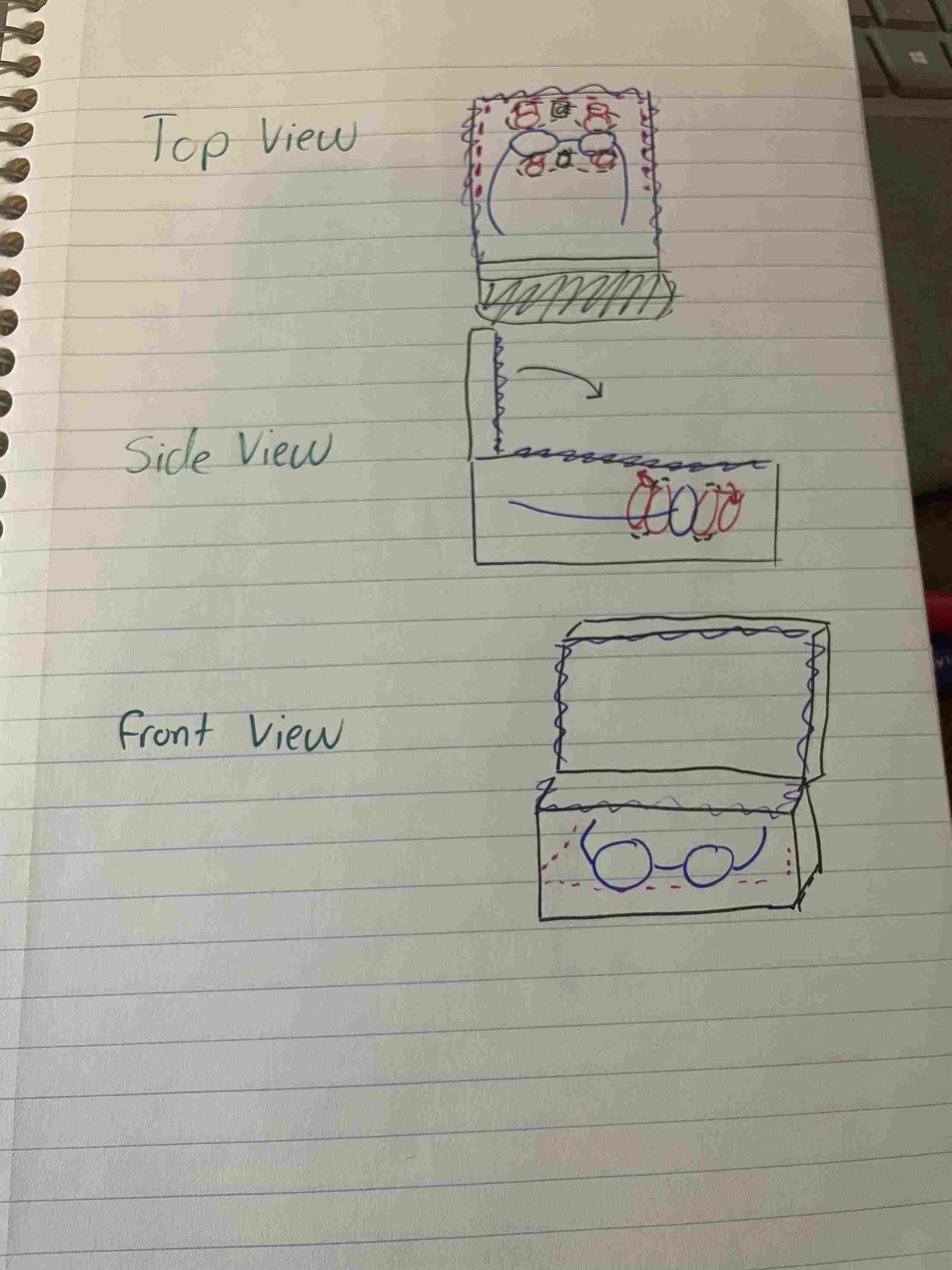
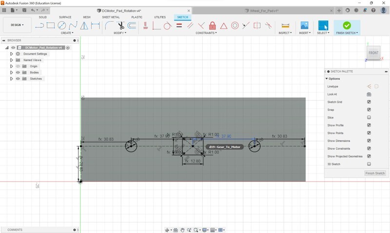
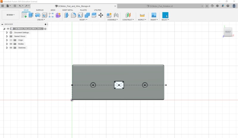
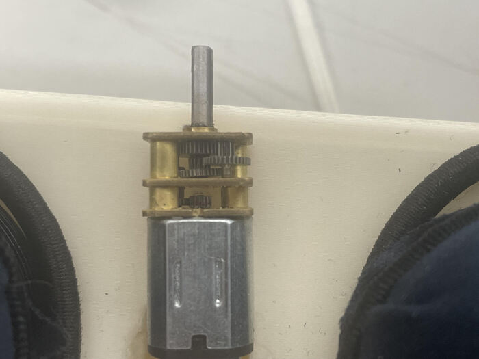
My new design, that Dr. Fagan helped me create, requires the user to place the glasses in between the cleaning pads. Once the pads will be rotated by a single DC motor using a pully system. As the motor rotates the pads will rotate as well. While the pads are manually cleaning the lenses, germicidal UV light will sterilize the frames. I expect the wavelength of the UV light to be around 265 to 285nm. I am experiencing some problems finding UVC LEDs in time. The picture of the DC motor is below that Dr. Fagan
The view of the full machine is below. In the first image the purple represents the magnets. The magenta represents the UV light surrounding the glasses
Bill of Materials
Total: $203.15
Satshakit
| Component | Quantity | Price Per Component |
|---|---|---|
| ATmega328p | 1 | $3.11 |
| 100nf Capacitor | 2 | $0.24 |
| 22pf Capacitor | 2 | $1.61 |
| 1uf Capacitor | 1 | $0.19 |
| 10uf Capacitor | 1 | $0.53 |
| 16Mhz Crystal Clock | 1 | $0.07 |
| Tactile Button | 1 | $0.42 |
| 499 Ohm Resistor | 2 | $0.10 |
| 10k Ohm Resistor | 1 | $0.10 |
| Red LED | 2 | $0.22 |
| Vertical Headers | 27 | $0.40 |
DC Motor Board
| Component | Quantity | Price Per Component |
|---|---|---|
| ATtiny1614 | 1 | $0.99 |
| 1uf Capacitor | 1 | $0.19 |
| 330 Ohm Resistor | 1 | $0.52 |
| Red LED | 1 | $0.22 |
| Vertical Headers | 5 | $0.40 |
| Horizontal Headers | 7 | $0.42 |
Power and Ground Board
| Component | Quantity | Price Per Component |
|---|---|---|
| Red LED | 1 | $0.22 |
| 330 Ohm Resistor | 1 | $0.52 |
| 3.3V Regulator | 1 | $0.67 |
| PAEW HW-769 Micro USB | 1 | Currently Unavailable |
| Vertical Headers | 22 | $0.40 |
LED Board 2x
| Component | Quantity | Price Per Component |
|---|---|---|
| 330 Ohm Resistor | 3 | $0.52 |
| Blue LED (Would normally be a UVC LED) | 3 | Blue LED: $0.06 UVC LED: $0.75 |
Mechanical
| Component | Quantity | Price Per Component |
|---|---|---|
| uxcell DC Motors | 2 | $7.87 |
| H-Bridge Motor Driver | 1 | $12.99 |
| SSD1306 OLED Display | 1 | $6.99 |
| RC522 RFID Sensor and Card | 1 | $5.49 |
| Female to Female jumper wires | 1 Pack | $6.98 |
| Flexible Wires | 2 Rolls (power and ground) | $14.44 |
| Heat Shrinks | 8 | $10.99 |
| Microfiber Cloth | 4 | $8.09 |
| Hair Bands | 8 | $5.87 |
| 1/8 in Wood | 12x4 in | $9.95 |
| 1/2 in wood | 24 x 24 in | $33.20 |
| Wood Glue | 1 Tube | $6.48 |
| Roll of Filament | 1 | $29.99 |
Platform IO
As mentioned in my embedded programing documentation I downloaded Platform IO to use with my Arduino projects and my ATtiny boards. The video I used for installation is here. After doing that I was ready. The use of the IDE was simple. Start a project, select your board and it will do the rest. I recommend installing some C++ extensions for easy text editing
The IDE is beautiful due to VSCodes powers. However, as I progressed to more complex code I realized that their were some limitations in the IDE that the Arduino IDE makes us take for granted. For example, including a library or declaring functions
Including A Library
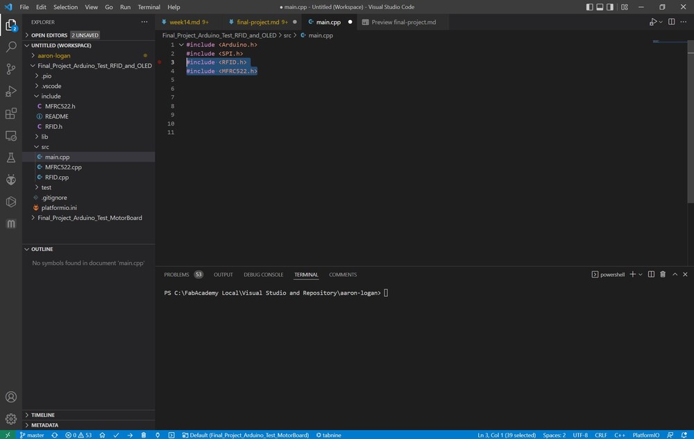
For my input week I initially wanted to use Platform IO, but this required a certain library for RFID cards that PIO didn’t have. PIO has multiple libraries that you can download but I wasn’t sure of the RFID library that I was using so I wanted to find ways to include it. After searching google I came across this community post with the answer that I was looking for.
It turns out that I have to include the library header file and the .cpp file. The .cpp file goes in the src section of the platform IO project while the header file goes in the Include section. I made the mistake of putting the .cpp files in the library section and was receiving errors for functions that were declared in the libraries.
The way I went about including it was downloading the .zip file with the header and .cpp file. I extracted the files and placed them into a folder for safe keeping. After I found the directory where my board project was, I placed the files into the respective directory. After that I wasn’t receiving any errors and the code was able to compile. Below I have an example of where I was able to encoporate my RFID libraries in PIO and it worked.
Calling Functions
I tried to migrate some code from my documentation into PIO, but I was receiving an error regarding the function not being declared. After again searching through google I came across this website and user maxgerhardt explained things perfectly
What I understood from the explanation was that Arduino interprets its files as .ino files which is able to pre-process which “pre-declares all known function prototypes”. However, PIO src uses .cpp files which can’t implement the pre-processing that a .ino can. There are two ways that one can solve the problem
- Rewrite
.inointo.cppusing this link which is the method that I used. When using the Arduino IDE, users code with .ino assistance but PIO can’t understand that, but can change the code to make it act like a .cpp which is what PIO can interpret, compile, and upload. - Rename the file as
main.inoinstead ofmain.cppwhich platform IO will support but there is a downside. VSCode Intellisense cannot work because the plugin won’t work with an Arduino INO file.
After reading the documentation I realized that the only change I had to make was declare the function at the beginning of the file. The file that didn’t compile was this
#include <Arduino.h>

void setup() {
  pinMode(3, OUTPUT);
}

void loop() {
  LED();
}

void LED()
{
  digitalWrite(3,HIGH); //
  delay(1000);
  digitalWrite(3, LOW); //
  delay(1000);
}
The file that worked was this
#include <Arduino.h>

void LED();

void setup() {
  pinMode(3, OUTPUT);
}

void loop() {
  LED();
}

void LED()
{
  digitalWrite(3,HIGH); //
  delay(1000);
  digitalWrite(3, LOW); //
  delay(1000);
}
The only thing that I changed was the void LED(); function at the beginning of the file. This is what worked and I wasn’t receiving any errors in regards to declared functions.
Electrical Designing
Initally my plan for my electronics was to network every component with its own board. Though, after talking with Dr. Harris he helped me realize that I could just use a Satshakit for the RFID and the OLED display, and use another board for motor control. This idea was much easier and managable for a couple of reasons. One, it decreases the amount of variables in the project. Two, it decreases the amount of networking needed. As I realized through some testing, trying to network a signal between three different nodes creates a delay. I2C is already a slower signinaling type than others, coupled with networking multiple nodes, multiple problems could’ve been created.
With this in mind the only parts I ended up designing was the DC motor board and the power board. For the Satshakit I looked at the documentation mentioned above.
Using Arduino
OLED
For asthetic purposes, I wanted to use an OLED display as a timer once the DC motors would stop spinning. The OLED I’m using is a SSD1306. This type of OLED uses I2C communication which was something I was used to due to networking week and input week. I was able to get it to light during input week and I used my documentation for that. The next step was to create a timer for the OLED. I searched the whole internet for some documentation on a timer, their was some but not anything useful, so I decided to make my own. The code itself is simple, but getting to that point was hard. First, I had to get it to display a number. Using this documentation I was able to get some text on the display. The libraries needed were in the PIO library tab and including them was easy. Though their was an error that said I needed to include another library called Adafruit_I2CDevice, I assume that this library is already built into the Arduino IDE and it doesn’t need to be declared, but I had to in PIO. The line of code was #include <Adafruit_I2CDevice.h>
My next goal was to put a decreasing number. This step was much harder as their wasn’t much documentation on OLED timers that were applicable to me. I had an idea of having a display variable be a number then subtract 1 from that and store it back in the display variable. I needed to use a for loop with a certain interval that the display variable would decrease. Their was a lot of configuration during this process. Sometimes, the display variable would show every number as it decreased, and sometimes it would stay the same, even after a couple of seconds passed. Eventually, I was able to get the number 60 to go down to 0 using a delay after every subtraction. Then expanding upon this idea, I wanted to use intervals of hundreths of a second. To do this, I had to use floats instead of integers because I needed decimals. I also had to make the delay 10 miliseconds instead of 1000 milliseconds. Then finally I had to make the for loop a little less than 3000, 2995 to be exact. I’m not exactly sure why this number works, but the timer stops at zero with this interval. I belive it has something to do with the delay. Regardless, after testing the code I was able to get it to print the variable in the serial terminal.
Then after some more configuration I was able to get the number to display on the OLED, the loop function that I used is below along with the classes and libraries.
#include <Adafruit_I2CDevice.h>
#include <Adafruit_SSD1306.h>
#include <Adafruit_GFX.h>

#define SCREEN_WIDTH 128 // OLED display width,  in pixels
#define SCREEN_HEIGHT 64 // OLED display height, in pixels

Adafruit_SSD1306 oled(SCREEN_WIDTH, SCREEN_HEIGHT, &Wire, -1);

float a;
float x = 60.02;
float b = 0.02;

void OLED_Timer()
{
  for (int i = 0; i <= 2995; i++)
  {
    x = x - b;
    a = x - b;
    delay(10);
    oled.clearDisplay();      // clear display
    oled.setTextSize(3);      // text size
    oled.setTextColor(WHITE); // text color
    oled.setCursor(24, 20);
    oled.print(a);
    oled.display();
  }
}
RFID and OLED combined
The next step was to begin the timer once the RFID card was scanned. I was already used to using the RFID sensor during input week, so I just used my docmuentation from earlier to get the code.
Though I wanted to do a couple of things in addition to the timer. I wanted the OLED to display a prompt, asking for the RFID card, and also add some ending text after the timer is finished. This part was relativily easy compared to the timer. In the RFID function, I created a beginning display function for the OLED that read “RFID ?” and added that before the RFID if statement with the timer loop. I then created an after display function that read “Thanks !” and put that after the timer function ran. I was able to connect both the OLED and the RFID sensor together because the RFID uses SPI instead of I2C communication and the arduino has enough pins for both.
Networking OLED and RFID to Motor Board
Now that I was done with the OLED and RFID, I needed to network another arduino for motor control. I am using I2C communication because that is what worked for me during networking week. Arduinos have 2 pairs of I2C pins, so I was able to get the OLED display and networking to work together, because the OLED takes up 1 pair. I went back to my documentation to refresch myself on I2C communication. After talking with Dr. Harris he had the idea of sending a start and stop signal, a byte 1 and a byte 0 being start and stop respectivly. I was looking through my documentation and I ran into some issues. The data wasn’t being sent correctly. I tried to copy everything word for word but I wasn’t able to recieve anything in the serial terminal. I realized that it had something to do with the while loop.
To impliment a condition or function that uses the data that was transmitted, the intended function has to be within the while loop containing the wire.Avaliable function along with the variable being stored with the Wire.read function.
When I use a while loop with the wire.Avaliable function, the function within the loop will continue even if data isn’t being transmitted. Though if I use an if statement with the wire.Avaliable function, then the functions within the statement will only go on only if data is being transmitted. For example my code looked like this,
.
.
.
while (wire.Avaliable()){
  int var = wire.Read()

  if(var == 1){
    example code
  }
}
With this example, the function runs forever once the condition is met, regarless if data is being transmitted.
Once I came to this realization, I was able to transmit data with ease. I first wanted to be able to light an LED. After some quick coding I was able to get that done.
My next goal was to use the my output documentation along with my mx1508 motor driver, to get the motors to spin. The coding was easy, I used the analogWrite function for the PWM pins and signal and a normal digitalWrite function for the constant pin. I had to make sure that the constant pins were set at LOW so the PWM pin value is the percentage that the motor is spinning at. This was the code that turnned on the motors.
analogWrite(PWM_1, 80);
digitalWrite(Constant_1, LOW);

analogWrite(PWM_2, 80);
digitalWrite(Constant_2, LOW);
This is the code that turnned off the motors
analogWrite(PWM_1, 0);
digitalWrite(Constant_1, LOW);

analogWrite(PWM_2, 0);
digitalWrite(Constant_2, LOW);
The final step was to run the code above if the correct byte of data is recieved. When I run the timer function I will have the master arduino send a byte “1” of data to the studnet motor arduino. The steps for the signinaling process is below.
- Send a 1 byte of data from parent board once RFID senses correct card
- Data is stored using
Wire.read();within theWire.availablewhile loop. - If statement checks if data is 1 or 0, if 1 then motors spin
- After 60 seconds, the master sents a 0 byte
- if statement checks if data is 1 or 0, if 0 then motors turn off.
Once I finished the code, everything worked. This is the master arduino code.
#include <Arduino.h>
#include <SPI.h>
#include <RFID.h>
#include <Wire.h>
#include <Adafruit_I2CDevice.h>
#include <Adafruit_SSD1306.h>
#include <Adafruit_GFX.h>

#define SCREEN_WIDTH 128 // OLED display width,  in pixels
#define SCREEN_HEIGHT 64 // OLED display height, in pixels

#define SS_PIN 10
#define RST_PIN 9
RFID rfid(SS_PIN, RST_PIN);
Adafruit_SSD1306 oled(SCREEN_WIDTH, SCREEN_HEIGHT, &Wire, -1);
String rfidCard;

void OLED_Timer();
void Start_Motor();
void Stop_Motor();

float a;
float x = 60.02;
float b = 0.02;
int s;
byte Starting_Number = 1;
char Ending_Number = 0;

void setup()
{
  Serial.begin(9600);
  Serial.println("Starting the RFID Reader...");
  oled.begin(SSD1306_SWITCHCAPVCC, 0x3C);
  SPI.begin();
  rfid.init();
}

void loop()
{
  oled.clearDisplay();      // clear display
  oled.setTextSize(3);      // text size
  oled.setTextColor(WHITE); // text color
  oled.setCursor(24, 20);
  oled.print("RFID?");
  oled.display();

  if (rfid.isCard())
  {
    if (rfid.readCardSerial())
    {
      rfidCard = String(rfid.serNum[0]) + " " + String(rfid.serNum[1]) + " " + String(rfid.serNum[2]) + " " + String(rfid.serNum[3]);
      Serial.println(rfidCard);
      if (rfidCard == "124 98 66 24")
      {
        Start_Motor();
        OLED_Timer();
      }
    }
    rfid.halt();
  }
}

void OLED_Timer()
{
  for (int i = 0; i <= 2995; i++)
  {
    x = x - b;
    a = x - b;
    delay(10);
    oled.clearDisplay();      // clear display
    oled.setTextSize(3);      // text size
    oled.setTextColor(WHITE); // text color
    oled.setCursor(24, 20);
    oled.print(a);
    oled.display();
  }

  Stop_Motor();

  x = 60.02;
  oled.clearDisplay();      // clear display
  oled.setTextSize(2);      // text size
  oled.setTextColor(WHITE); // text color
  oled.setCursor(24, 20);
  oled.print("Thanks!");
  oled.display();
  delay(5000);
}

void Start_Motor() {
  Wire.beginTransmission(2);
  Wire.write(Starting_Number);
  Wire.endTransmission();
  Serial.println(Starting_Number);
}

void Stop_Motor() {
  Wire.beginTransmission(2);
  Wire.write(Ending_Number);
  Wire.endTransmission();
}
One aspect that I saw being ans issue but thankfully wasn’t an issue was the flash memory usage. My origianl idea was to use a ATtiny1614 but that only has 16000 bytes of data, but the master code uses an estimate of 18000 bytes of memory. Looking at this screen shot, I deleted some of the libraries and tested to see if the code would compile for a ATtiny1614 and it barley did.
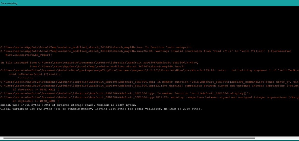
The amount of libraries that I had to use, especially the OLED libraries, took up a major amount of memory. Thankfully at ATmega328P has roughly 32000 bytes of memory which was more than enought.
The code below is for the student arduino that controls the motors.
#include <Arduino.h>
#include <Wire.h>

#define PWM_1 3
#define PWM_2 5
#define Constant_1 2
#define Constant_2 4

int var;

void Motor_func();

void setup()
{
    pinMode(PWM_1, OUTPUT);
    pinMode(PWM_2, OUTPUT);
    pinMode(Constant_1, OUTPUT);
    pinMode(Constant_2, OUTPUT);
    Wire.begin(2);
    Serial.begin(9600);
    Wire.onReceive(Motor_func);
}

void loop()
{
    delay(1000);
}

void Motor_func()
{
    while (Wire.available())
    {
        var = Wire.read();
        Serial.print(var);

        if (var == 1)
        {
            analogWrite(PWM_1, 80);
            digitalWrite(Constant_1, LOW);

            analogWrite(PWM_2, 80);
            digitalWrite(Constant_2, LOW);
        }
        if (var == 0)
        {
            analogWrite(PWM_1, 0);
            digitalWrite(Constant_1, LOW);

            analogWrite(PWM_2, 0);
            digitalWrite(Constant_2, LOW);
        }
    }
}
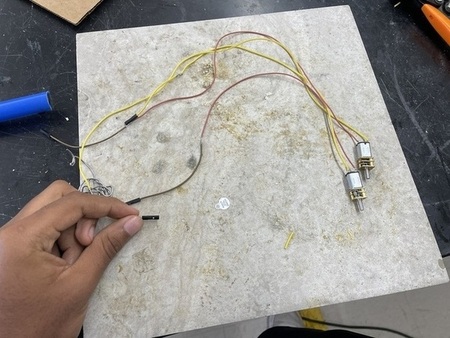
For the actual motors I had to solder some flexible wires that the lab had because the motors needed to wrap around the frame of the cleaner.
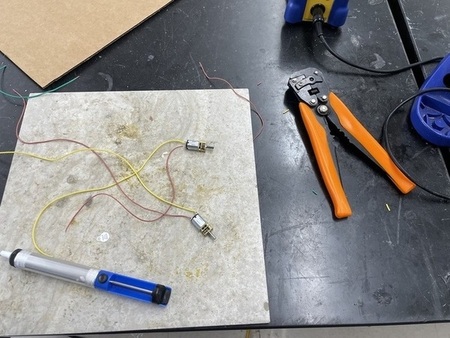
I also had to solder some female jumper wires so that the motors could connect to the motor driver. I originally was going to use wire tape, but Mr. Dubick insisted that I use shrink wrap and he was completely right, I will never use wire tape ever again.
It was really easy to use and it held a more secure connection.
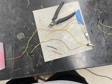
I went to plug in the motors to the motor driver and I ran the code, initally only one motor worked. Though, after some resoldering of the motor that didn’t work, I was able to get both of the motors to function.
This video shows the motors starting
This video shows the motors stopping then restarting
My Own Boards
DC Motor Board
My next goal to finish the electronics was to create a single motor board, and a common ground board. I planned to create a motor board, but I realized that I already made one during networking week that I never used.
I used my Electronic Design documentation I was able to design the common ground and power board board with ease.
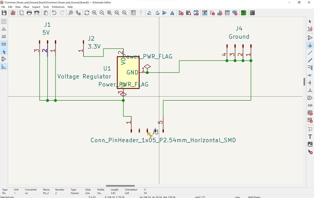
Power Board
These were the components that I used
- ATtiny1614
- Resistor
- LED
- Headers for TX and RX
- Headers for motor driver
- Headers for SDA and SCL
- Headers for USB power supply
- ZLDO1117 Voltage Regulator for the RFID Sensor
I made sure to add power flags and to hide the pins that I wasn’t using. I also had to reference the ZLDO1117 datasheet to see exactly what the VIn and VOut meant. VIn was for 5V and VOut was where I connected the 3.3V RFID sensor to. I also wanted to include a PAEW HW-769 Micro USB for power. For that I needed to use a 5 pin header and solder the component to the headers.
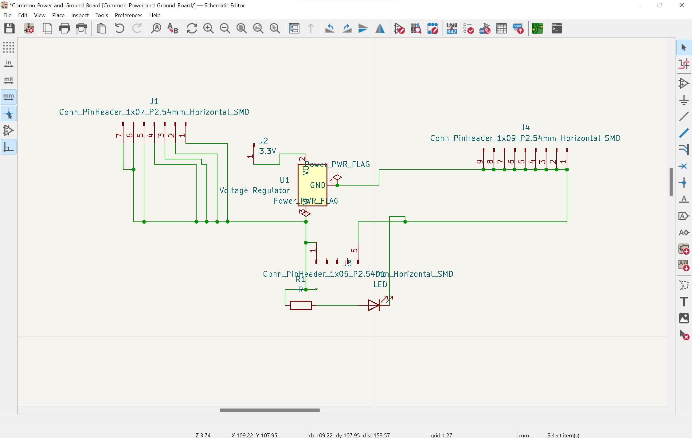
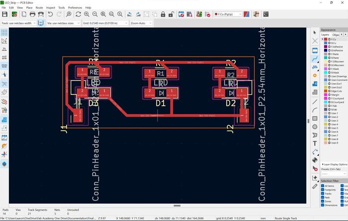
After designing this was the final schematic product
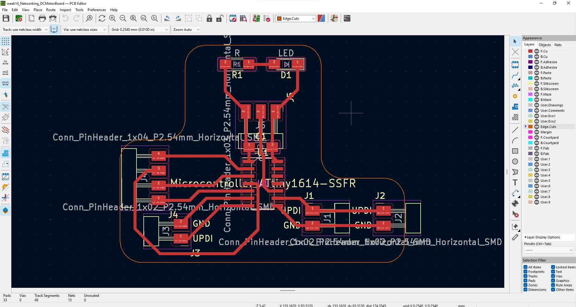
After bringing in all of the components I started connecting traces, but first I had to change the constraints using my PCB design documentation.
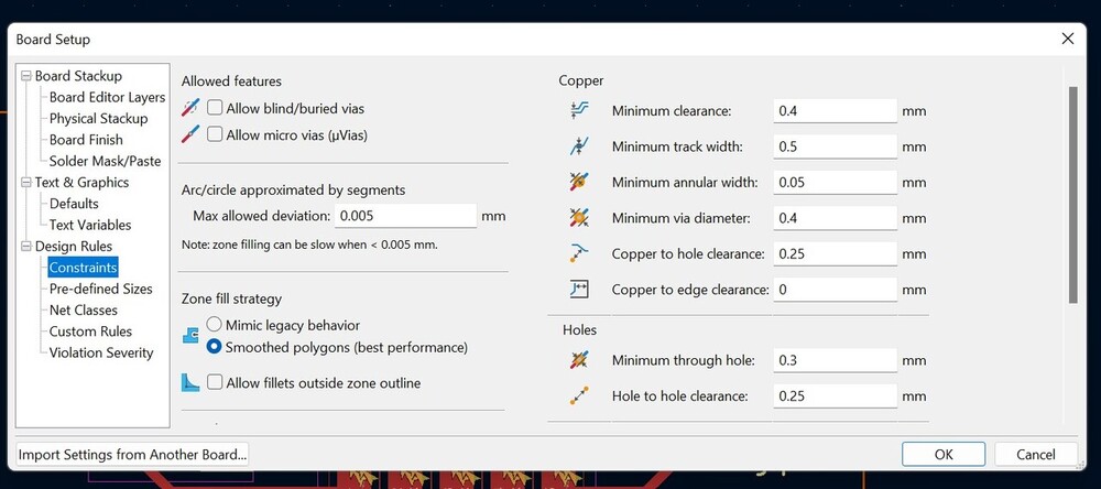
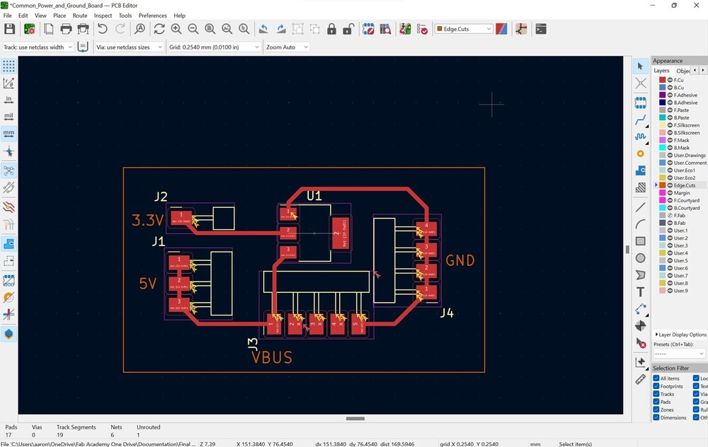
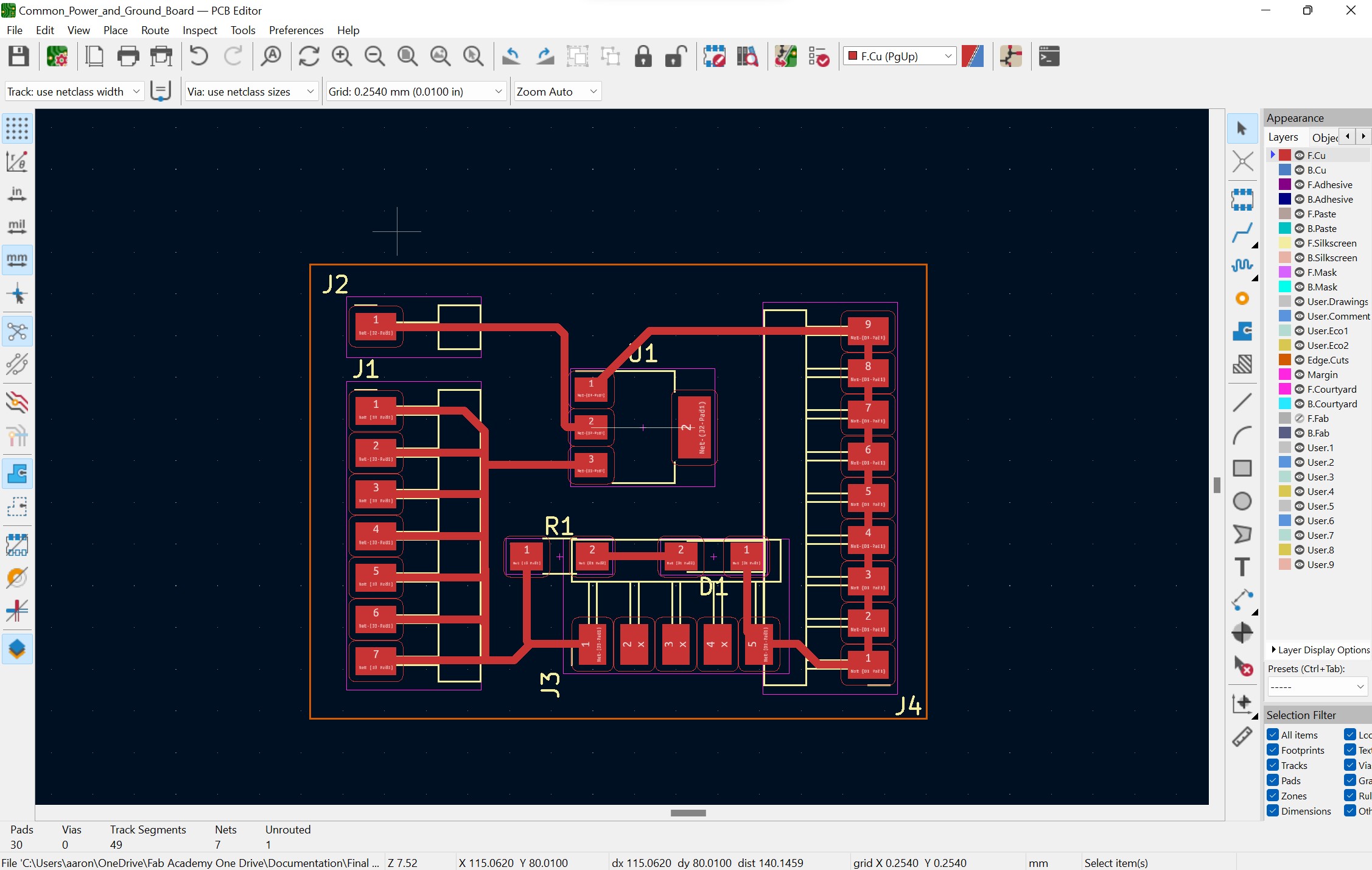
After connecting traces and adding an edge cut this was the final product
During this process I realized I made a big error I realized that I had the power traces connected in parallel not in seriese, meaning their would be a voltage drop. I also noticed that I had to use my seperate power source ealier than expected. I assumed that the Satshakit had VCC pins to send out to other sensors and likewise, ground wires for common ground. The board however didn’t have that and I was just able to get by using my common ground and power board mentioned earlier. Though I had to go back and add some more pins in the board design is preparation for networking the Satshakit to the motor board. I also decided to add a power LED just in case.
This is the schematic
This is the PCB editor
Milling
I put the files into Bantam tools and using my PCB Production documentation I milled the boards easily.
I realized after using the first power and ground board that I should use vertical headers. Using the horizontal headers before forced the wires to bend in an unnatural way. To prevend this, I used vertical headers and was much better. I also removed the PAEW HW-769 Micro USB from the old board and put it on the new board.
Programming
Getting Satshakit Set Up
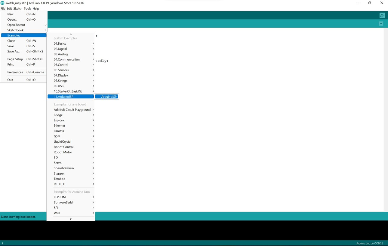
Similar to my ealier process I wanted to start with the RFID and OLED before I worked onto networking boards together. Using a Satshakit that I made using this GitHub link I first had to burn the bootloader. using the link I mentioned ealier along with this image I connected the arduino and tried to burn the bootloader.
Once everything was plugged in I went into Arduino IDE and followed the documentation.
- I selected Arduino Uno as the board
- Selected the right COM Port
- For Programmer I used: Arduino as ISP
Though I was receiving and error regarding the clock and how the Arduino couldn’t connect to the ATmega328p. Thankfully a Fab Academy student Andrew Jiang was used to using Satshakits because he had to create his own. Asked if I made the Arduino an ISP programmer, which is an aspect I forgot to do. He promted me to go the example that Arduino IDE provides.
Now that the Arduino was programmed I connected the Satshakit to the Arduino and I was able to burn the bootloader, and I was now able to use the Satshakit normally.
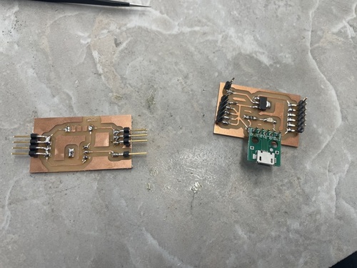
Programming The Satshakit
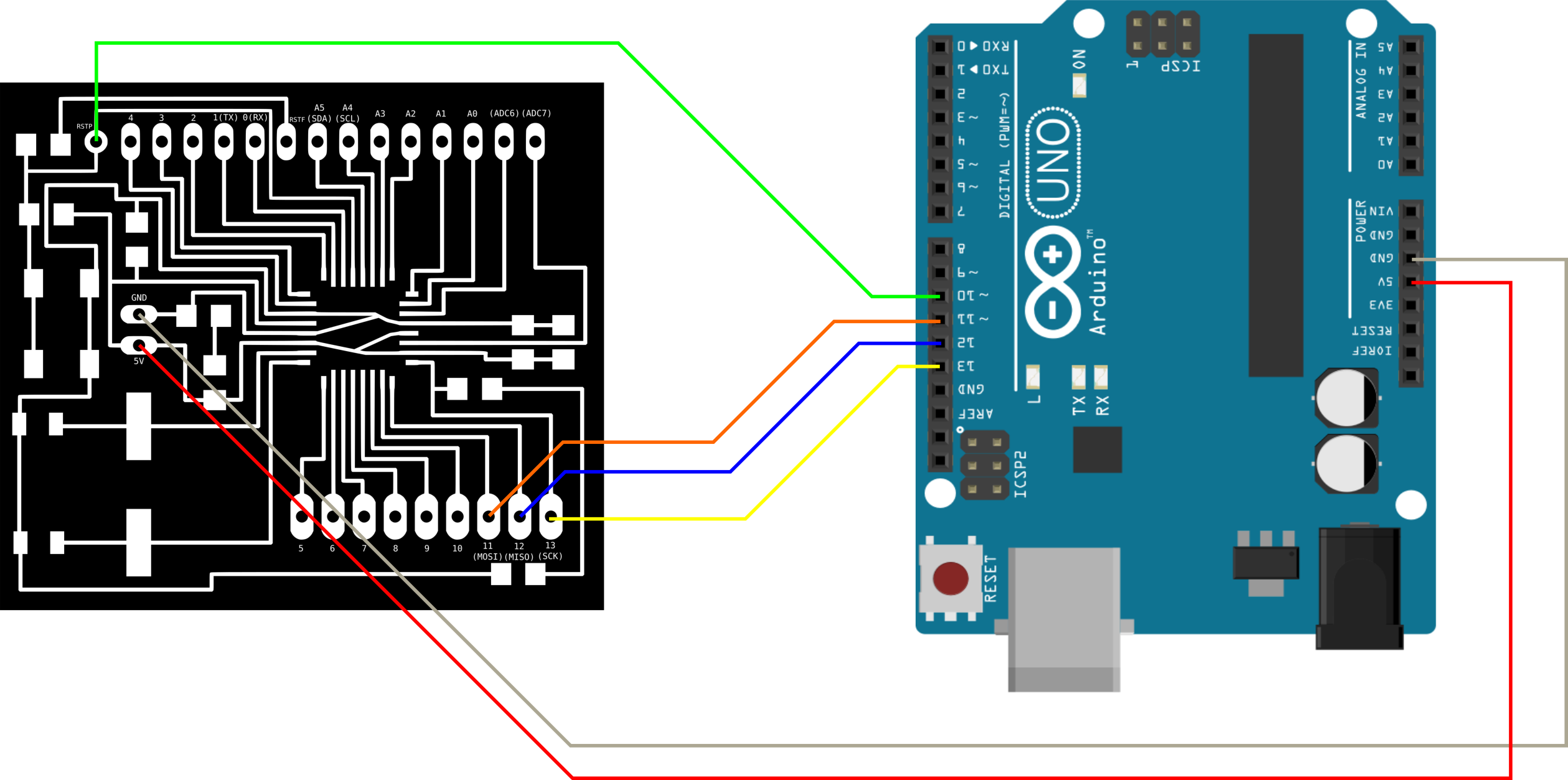
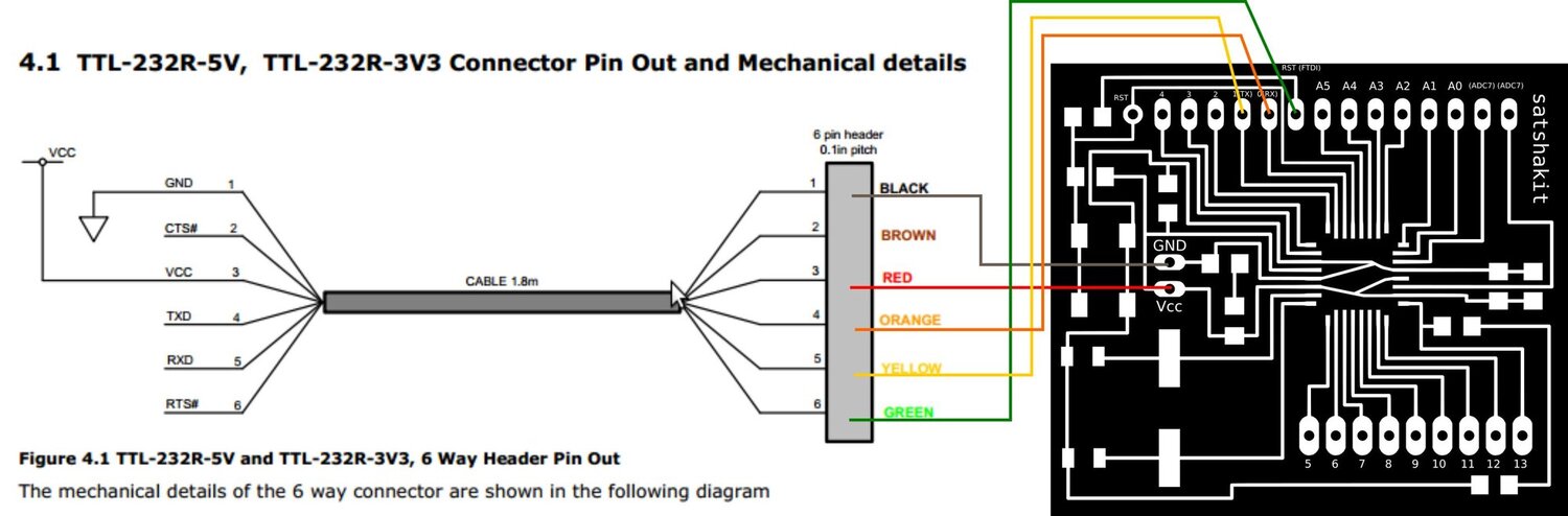
For the remainder of the documetntation I would reference this image a lot
To program the Satshakit I used a SparkFun FTDI Basic Breakout. The Github link had this image to help with the connection.
I loaded up Platform IO and began programming. This time I made sure to select an ATmega328p/AP board I first wanted to see if I could blink an LED, I typed some basic code and I was able to get the LED to blink.
Next I tried to encoporate the RFID sensor. Since the Satshakit uses the same board as an Arduino I could just use my input documentation and copy the pinouts directly. Because of this, I used the exact code from that week. I also made sure to include the .cpp and .h files in the PIO project for the libraries that I had to use. This configuration was easy and once I finished the code compiled and I could blink the LED using the RFID card.
Then I had to encoporate the OLED display. Again, the pinout was the same as an Arduino, so I plugged it in the exact same way and I used the code from ealier and everything worked.
Networking Boards
I went back to programming and the board was extremely useful. When I used the first power and ground board I had to disconnect everything to program the Satshakit, but now I could share common ground and plug in the other pins of the FTDI converter.
I used my networking documentation for the networking of the ATTiny1614, but first I had to program it. I decided to use an Arduino jtagupdi programer which I made using my PCB Production Documentation but I ran into some issues. I was receiving this error Error programming ATtiny1614: bad response to enter progmode command: RSP_ILLEGAL_MCU_STATE #45. I thought it had something to do with the Arduino programmer but after talking with Dr. Harris he said it was something with the chip itself. The chip isn’t able to enter program mode. Luckily I didn’t have to explore this issue because I had already made the same board for networking week and I was able to use that with no problems.
Since the motor board had a bus I could connect the OLED display their and also connect the bus together using the other set of pins. I used my Embedded Programming documentation to turn on the internal pullup resistor on the chip. This is the technique that I used to network the 1614 chips during networking week. These were the two lines of code that I used.
PORTB_PIN0CTRL |= PORT_PULLUPEN_bm;
PORTB_PIN1CTRL |= PORT_PULLUPEN_bm;
Knowing that the Satshakit was already programmed with the code for the OLED I thought I could just provide power and connect the SDA and SCL pins together for each node. I was able to but I ran into a huge bug. At first, the OLED display didn’t work but after switching the SDA and SCL pins on the OLED it turned on. I was extremely concerned because the SDA of the OLED connected to the SCL of bus and vice versa according to the pinout image from the Github Satshakit documentation. I thought it was something with the pullup resistor but if the RFID was turning on then the bus was working. Then I thought it was something with the pins on my own board but looking at the ATtiny1614 pinout the SDA and SCL pins were exactly where I thought they were.
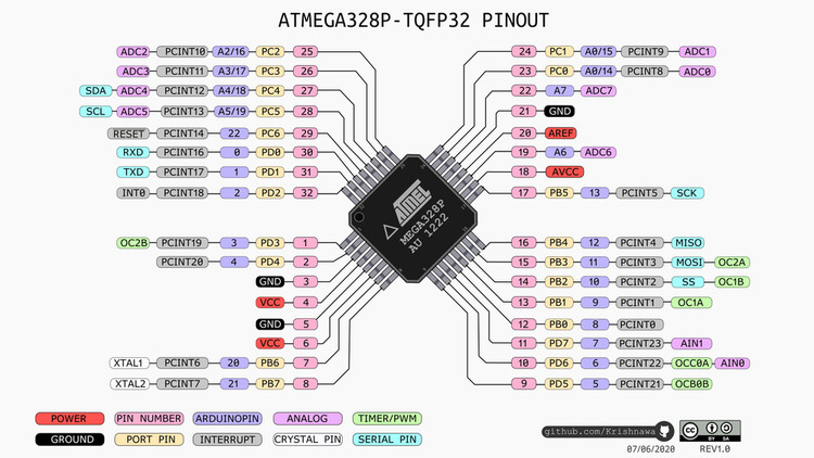
Then Dr. Harris helped me troubleshoot and even he was confused. Then we realized that it was the pinout of the satshakit and the pinout image that we were using. This is the image that I was referencing on the documentation, but the SDA and SCL labeling is wrong
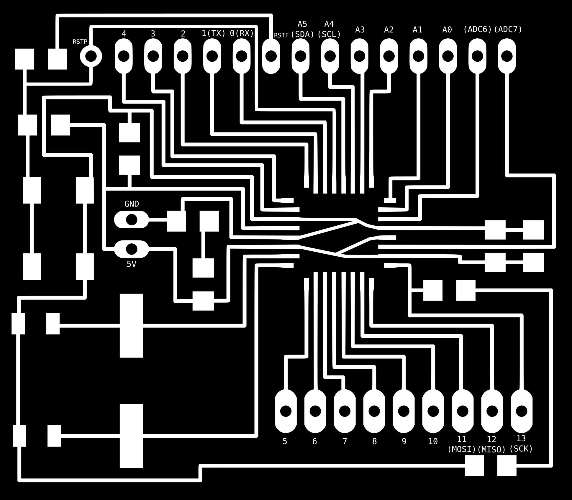
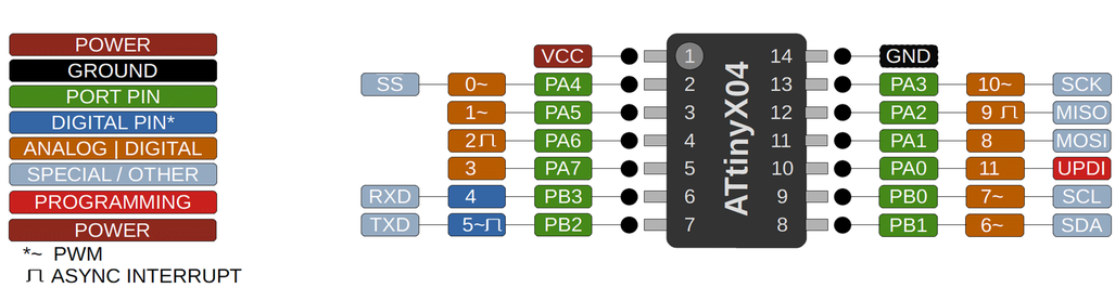
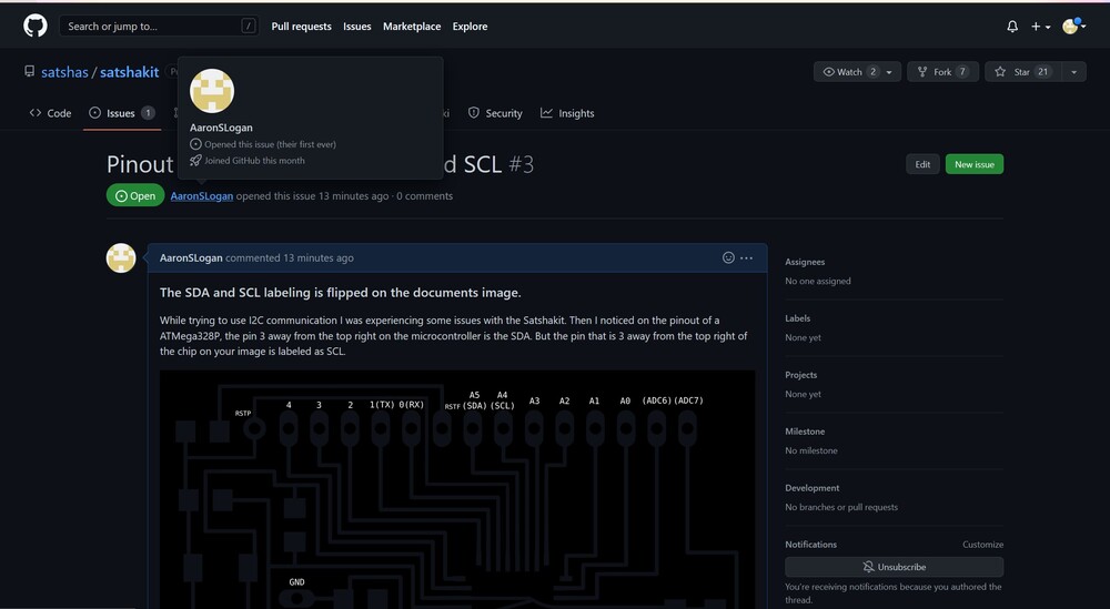
Looking at the ATmega328P pinout image above, the SDA pin is 3 from the top right of the chip, but the labeling on this image says that the pin 3 away from the top right is the SCL pin. I’m glad I noticed this error and I openned an issue on the Github page.
Now that the SDA and SCL issue was fixed, I was able to connect the I2C bus with ease and network the satshakit with my motor board. I touched up the motor board code by changing the pin numbers and everything was working properly. The RFID started the timer, then sent a signal to the motor board and both motors began to spin. They also turned off as the timer hit zero just like with the Arduinos. Also with the signle power source with common ground, everything turned on and off when the single wire was plugged in, exactly as I planned.
This was the Satshakit code
#include <Arduino.h>

#include <SPI.h>
#include <RFID.h>
#include <Wire.h>
#include <Adafruit_I2CDevice.h>
#include <Adafruit_SSD1306.h>
#include <Adafruit_GFX.h>

#define SCREEN_WIDTH 128 // OLED display width,  in pixels
#define SCREEN_HEIGHT 64 // OLED display height, in pixels

#define SS_PIN 10
#define RST_PIN 9
RFID rfid(SS_PIN, RST_PIN);
Adafruit_SSD1306 oled(SCREEN_WIDTH, SCREEN_HEIGHT, &Wire, -1);
String rfidCard;

void OLED_Timer();
void Start_Motor();
void Stop_Motor();

float a;
float x = 60.02;
float b = 0.02;
int s;
byte Starting_Number = 1;
char Ending_Number = 0;

void setup()
{
  Wire.begin();
  Serial.begin(9600);
  Serial.println("Starting the RFID Reader...");
  oled.begin(SSD1306_SWITCHCAPVCC, 0x3C);
  SPI.begin();
  rfid.init();
  pinMode(13,OUTPUT);
  pinMode(12, OUTPUT);
  pinMode(4, OUTPUT);
  pinMode(3, OUTPUT);
}

void loop()
{
  oled.clearDisplay();      // clear display
  oled.setTextSize(3);      // text size
  oled.setTextColor(WHITE); // text color
  oled.setCursor(24, 20);
  oled.print("RFID?");
  oled.display();

  if (rfid.isCard())
  {
    if (rfid.readCardSerial())
    {
      rfidCard = String(rfid.serNum[0]) + " " + String(rfid.serNum[1]) + " " + String(rfid.serNum[2]) + " " + String(rfid.serNum[3]);
      Serial.println(rfidCard);
      if (rfidCard == "124 98 66 24")
      {
        delay(200);
        Start_Motor();
        OLED_Timer();
      }
    }
    rfid.halt();
  }
}

void OLED_Timer()
{
  for (int i = 0; i <= 2995; i++)
  {
    x = x - b;
    a = x - b;
    delay(5);
    oled.clearDisplay();      // clear display
    oled.setTextSize(3);      // text size
    oled.setTextColor(WHITE); // text color
    oled.setCursor(24, 20);
    oled.print(a);
    oled.display();
  }

  Stop_Motor();

  x = 60.02;
  oled.clearDisplay();      // clear display
  oled.setTextSize(2);      // text size
  oled.setTextColor(WHITE); // text color
  oled.setCursor(24, 20);
  oled.print("Thanks!");
  oled.display();
  delay(5000);
}


void Start_Motor() {
  Wire.beginTransmission(2);
  Wire.write(Starting_Number);
  Wire.endTransmission();
  Serial.println(Starting_Number);
}

void Stop_Motor() {
  Wire.beginTransmission(2);
  Wire.write(Ending_Number);
  Wire.endTransmission();
}
Then this was the motor board control
#include <Arduino.h>

#include <Wire.h>


#define PWM_1 0
#define PWM_2 1
#define Constant_1 2
#define Constant_2 3

int var;

void Motor_func();

void setup()
{
    pinMode(PWM_1, OUTPUT);
    pinMode(PWM_2, OUTPUT);
    pinMode(Constant_1, OUTPUT);
    pinMode(Constant_2, OUTPUT);
    PORTB_PIN0CTRL |= PORT_PULLUPEN_bm;
    PORTB_PIN1CTRL |= PORT_PULLUPEN_bm;
    Wire.begin(2);
    Serial.begin(9600);
    Wire.onReceive(Motor_func);
}

void loop()
{
    delay(1000);
}

void Motor_func()
{
    while (Wire.available())
    {
        var = Wire.read();
        Serial.print(var);

        if (var == 1)
        {
            analogWrite(PWM_1, 80);
            digitalWrite(Constant_1, LOW);

            analogWrite(PWM_2, 80);
            digitalWrite(Constant_2, LOW);
        }
        if (var == 0)
        {
            analogWrite(PWM_1, 0);
            digitalWrite(Constant_1, LOW);

            analogWrite(PWM_2, 0);
            digitalWrite(Constant_2, LOW);
        }
    }
}
UVC LED Board
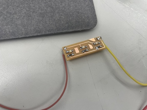
Unfortunatly I wasn’t able to get the UVC LED’s in time for the final presentation, so in its place I decided to use some blue LEDS. This board was really simple, just some 330 Ohm Resistor and the leds. I made sure to hold off on printing the design until I had the large case designed. This was the KiCad design and final image.
Mechanical Designing
For the mechanical designing part I had to design everything. From the outer wood case to the microfiber pads.
If some of the embedded Fusion 360 images aren’t working, reload the page and it will fix the error, Thanks!
Designing the Glasses Holders
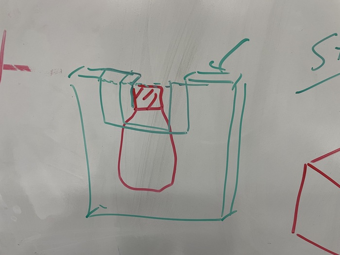
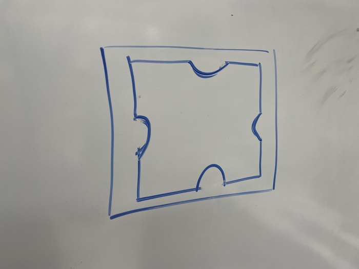
I wanted to encoporate molding and casting into my project. I knew I needed something to hold my glasses in place in case the pad rotation moved them and after talking with Dr. Harris and Dr. Fagan, I realized that I could use a flexible mold to hold the glasses in place. Dr. Fagan helped me draw this picture to reference. The red part was the frames of the glasses, the outer green part would be a strong solid piece to hold the flexible mold in the center.
Looking back at my Molding and Casting documentation I mentioned that I tried to use the milling machines for the flexible piece but the bit couldn’t cut a piece that thin, refering to this image.
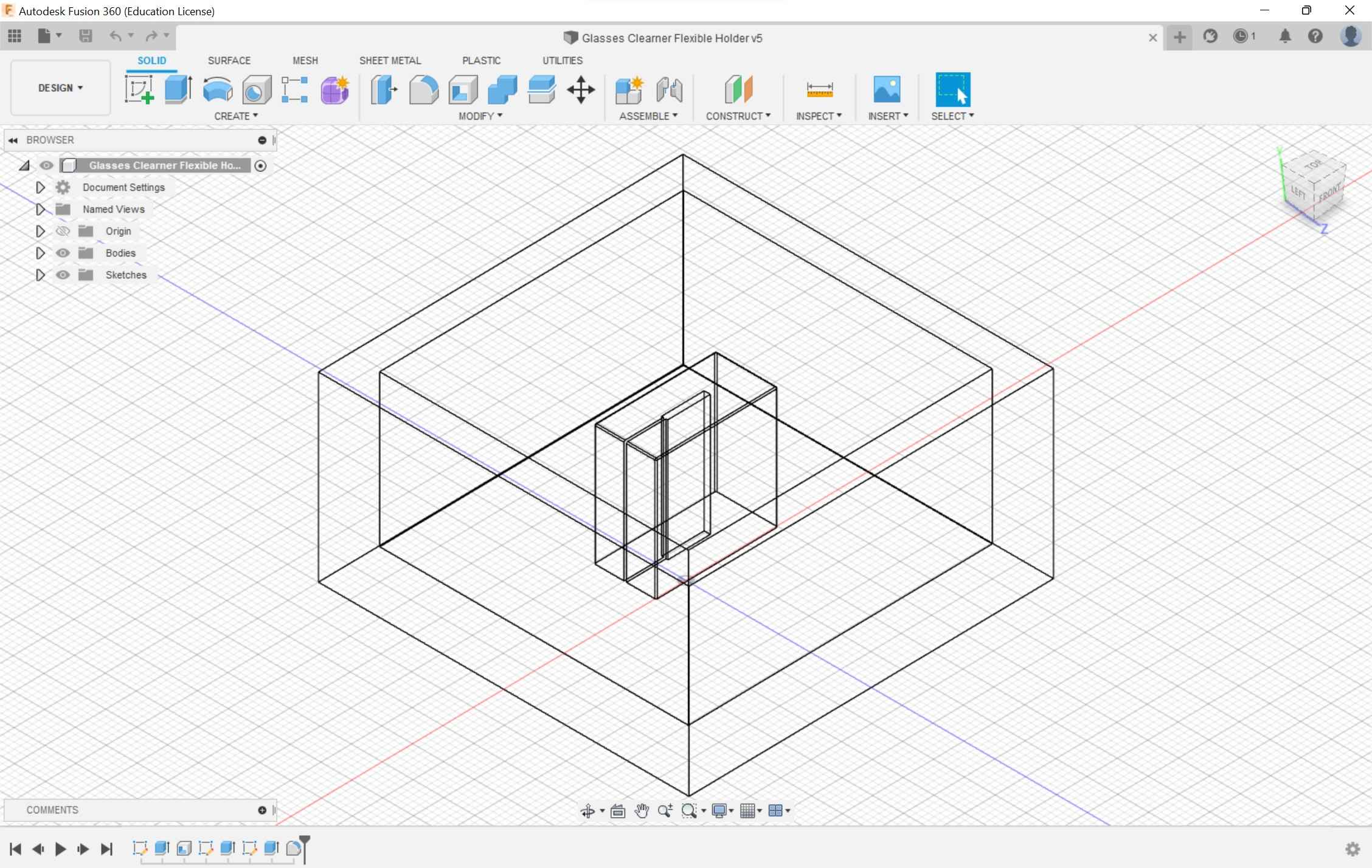
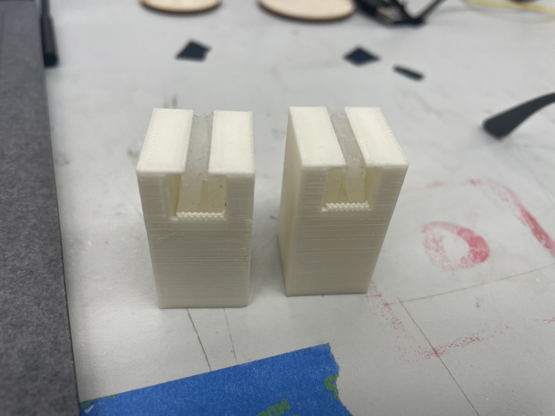
I went back to Fusion 360 and tried to redesign the mold. As I was thinking of ways to create a design I realized that I could use the technique from Molding and Casting week. During that week I had to mill a reverse clay mold, to create a strong mold, to mold a flexible piece. Though for the final project I realized that I could skip the reverse mold and just 3D print the strong mold, to create the flexible piece that I needed, this way I didn’t have to create a design with an extremely thin slit in the middle to hold my glasses.
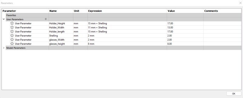
I went to designing in Fusion 360 using parametric designing that I learned from computer controlled cutting. I made some parameters for the length, width and height of the mold and then I had to create a parameter for what the width of the slit. I made sure to make the slit a little bit taller than the entire piece so it wouldn’t be covered. I also had the idea of just using an exacto knife to cut the mold so the mold so the glasses could be forced in and out but not by the machine because the cut was thin. After some designing I came up with these parameters and final design
I decided to use the Formlabs 3B+ Resin printer because that would have the most accurate values and could print something that was relativily thin. I exported the file as an STL from Fusion 360 and put it into PreForm slicer
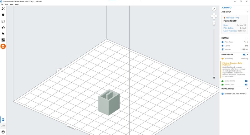
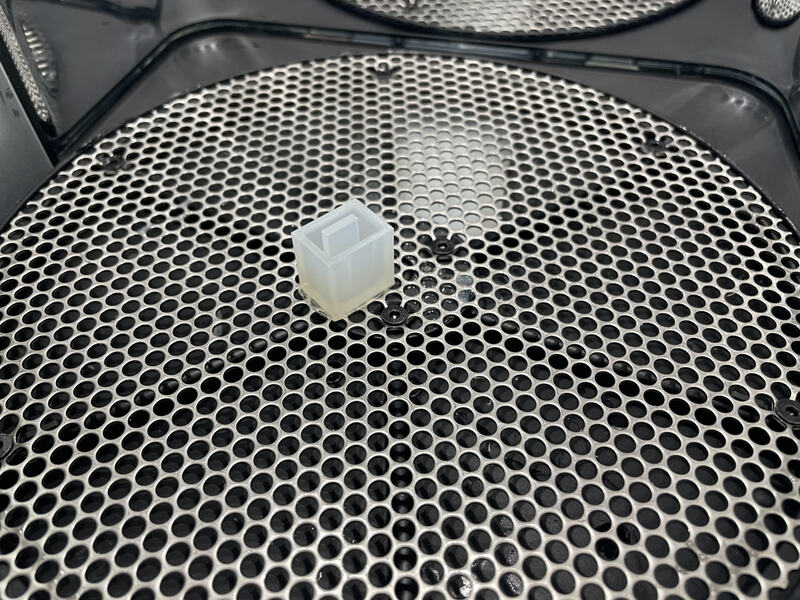
After that, I selected the printer that had a strong but slightly flexible material and printed it out. After the design printed, because I was using a resin printer, it had to bath in alchohol for 20 minutes then cure for 1 hour at 60 degrees celcius. This was the final product and Fusion 360 design.
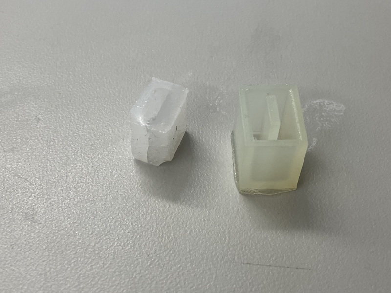
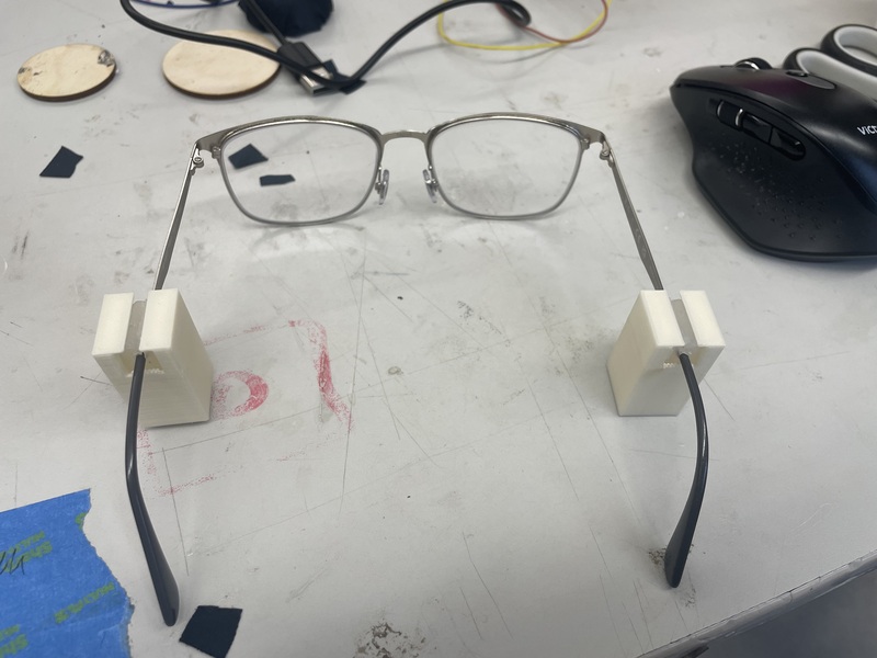
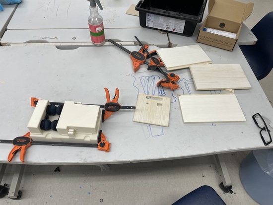
I used my molding and casting documentation to create the mold. First, I sprayed some Ease Realease 200, then looking at the specifications for Mold Start 20t, the ratio of 20T was 1:1 with a pot life of 6 minutes. Similar to last time I used a cup of water to estimate exactly how much of each type I needed. Then, after measuring, mixing then pouring the mold it I waited for it to cure. Once the mold was finished curing I had to pull it out. I struggled with this part because I didn’t design a way to take it out but I eventually did. I used the exacto knife to cut a slit and checked to see if they wrapped around my glasses, and they did first try surprisingly!
Flexible Mold Holders
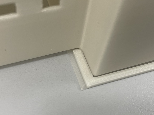
Now that the flexible piece was printed, I needed to create the container for it. I thought about the best way to hold the flexible piece and I figured that I needed support from the top and the edges so the piece didn’t move, then I also needed some compression from the sides to enhance the hold. I openned up Fusion 360 and went to designing. I had to make a couple of parameters before I created anything. I measured how height of my glasses frames from the bottom of the table then I realized something interesting. My glasses weren’t completely even, both lenses rested on the table along with one side of the frames, but the other side wasn’t touching the table. Below is a picture of what I am describing.
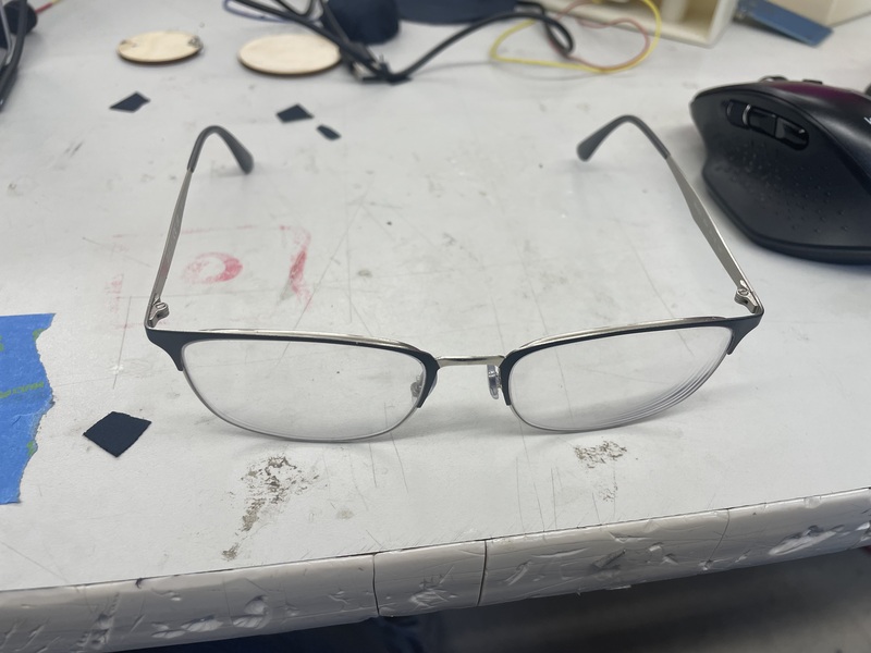
Due to this, I decided to measure the height from the side that touched the ground because the mold has the strength to hold the glasses in place, that why I created it. After creating a bunch of parameters, I had finished the design.
Though I had to print this multiple times because I couldn’t get the exact height of the glasses. Once I finished editing the parameters and printed the design, I was perfect.
Pad Holder
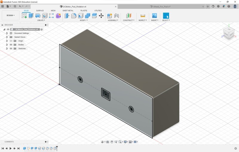
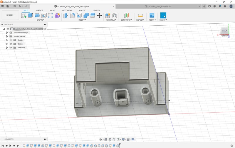
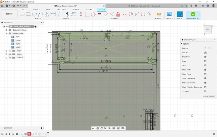
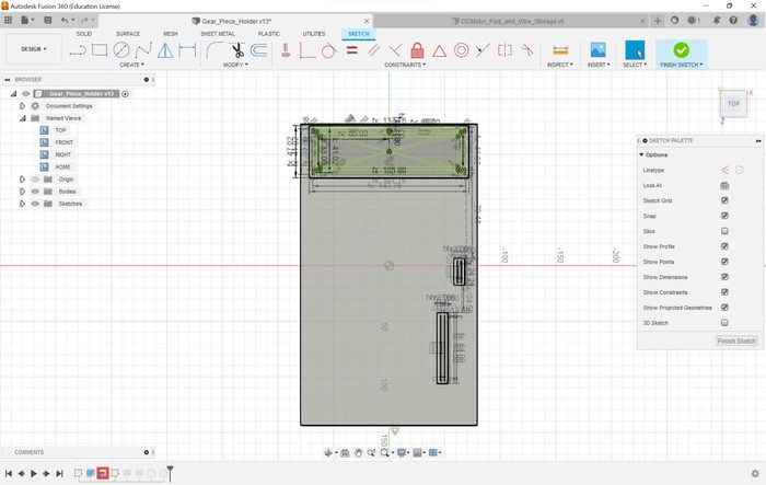
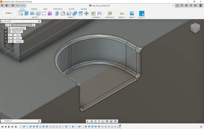
I had to desing something to hold the pads and the motor for the rotation. I already had an idea of what it would look like because of the mock design I created earlier. First I had to measure a lot of components such as the length width and height of my glasses, and likewise the motor, the distance from the edge of the glasses to the middle of the lens. After measuring I came up with these values. I inputted all of these parameters into Fusion 360 and went to designing.
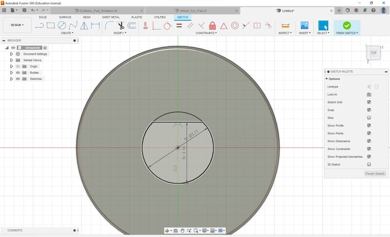
I first had to create a holder for the glasses and I used the parameters to measure exactly where it the holes should be and the size of them. I also knew that I needed two holes for the wheels that would rotate the pads and those would go exactly at the lens point. I could make the diameter of the whatever I wanted to so I decided on 6 mm. I made the distance parameters just construction lines and after creating the holes at the corresponding location I was finished with the holes.
The next step was to extrude the holes. I made the holes the exact width distance so the extrude went all the way through. Next, I shelled the design, what I didn’t take account for was that the shelling didn’t create a hole for the DC motor wires. So the DC motor hole was closed except for the openning which is something that I would have to drill out. Finally I added some fillets and my design was done
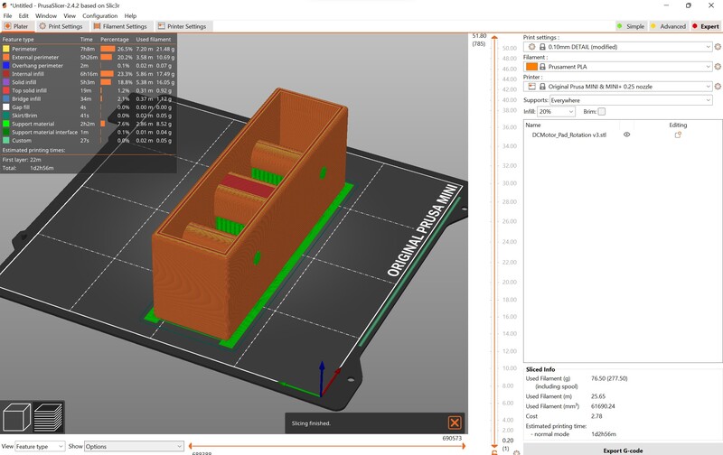
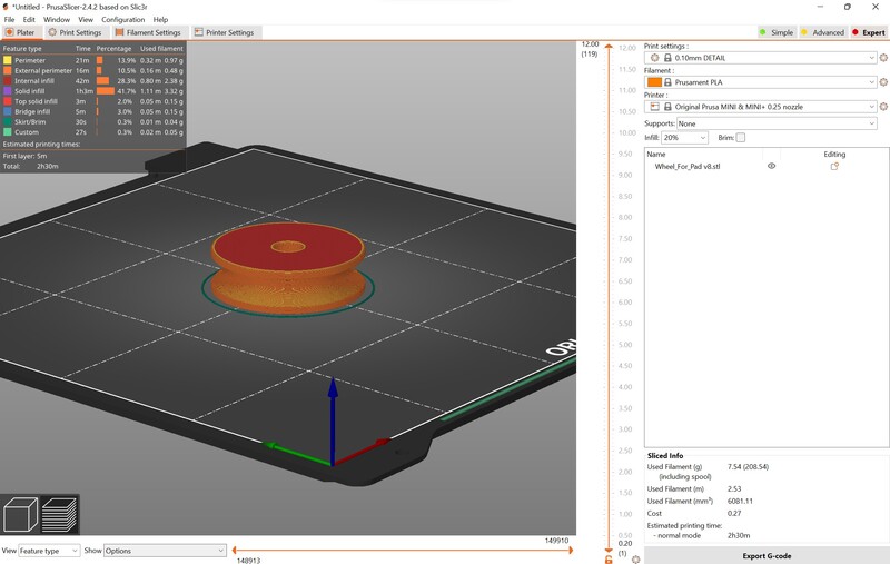
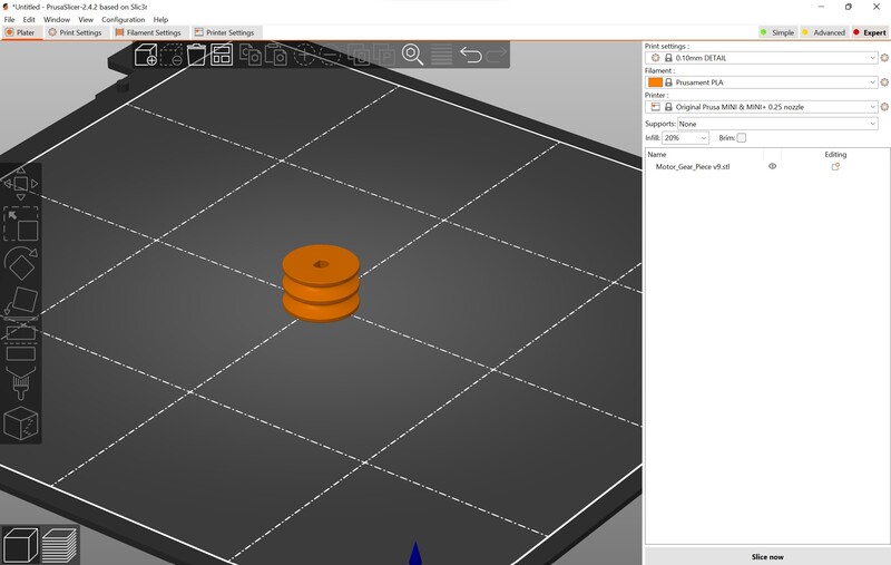
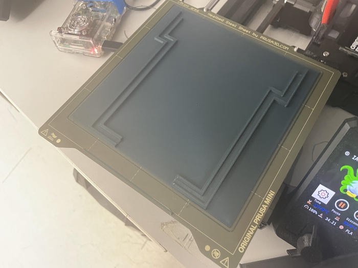
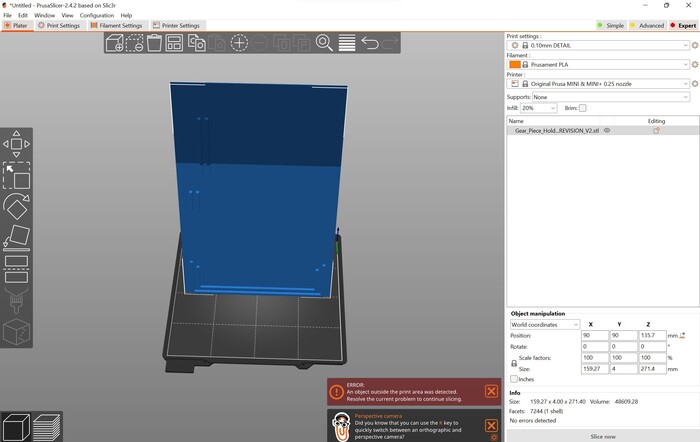
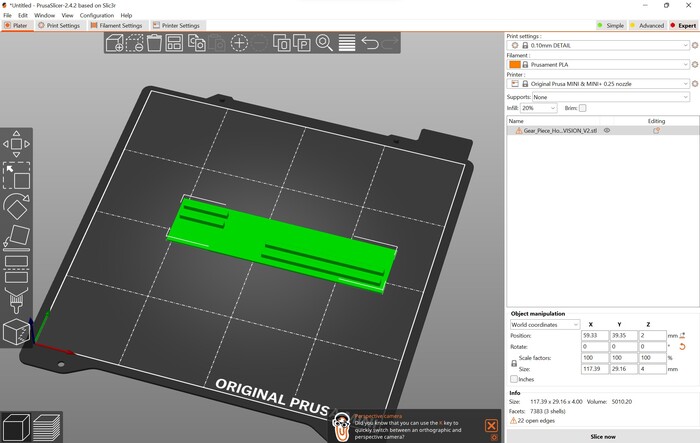
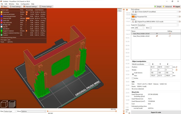
I exported the design as an STL and openned PrusaSlicer to slice the G-Code for the Prusa mini printers in the lab
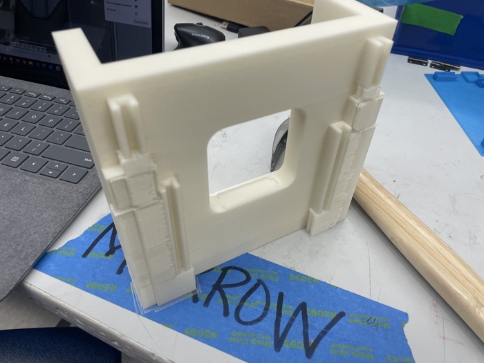
Once it was done printing I realized the mistake of the shelling not leaving a hole so I had to drill it out. Also as I was trying to put in the DC motor I realized that the hole was too small so I had to drill it out a little bit more. Once I did that I was done with the design.
Gear Piece, Rod and Gear Pad
Rod
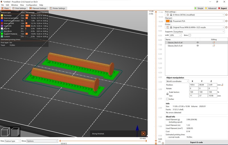
I began designing the rods which were simple. I used a diameter of a little less than 6 mm becasue I knew the filament would expand to cover that value, I also included a tap at the end to hold the gears in place as they rotated. I extruded the rod part to be the distance of the holder width and added some fillets and I was finished
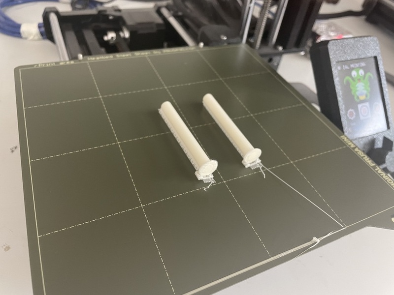
After that I sliced it then printed it
Gear Pad
I was going to use hair bands as the bands for the rotation. Looking at the bands in the lab most of them were either too short or had too much tension and would probably damage the motor. Hair bands had just enough tension that it would keep a grip but also not damage the motor. Their are definitely better alternatives and I will make note of that for a second design. With that in mind I had to make a parameter for the band thickness. Also I had to think of a way to have the band connect to the gear and taking inspiration from the milling machines in our lab I realized that I had to make a wheel with a minor divot. I still didn’t know the best way to do it though. I experimented with some different techinques but none of them amounted to the end result that I was looking for. Then, I found the revolve feature. I rarley use this but it was perfect for what I needed.
I created a sketch with a couple of parameters for the band thickness and some extra material on the top and bottom. Finally I made a parameter for the distance of the divot.
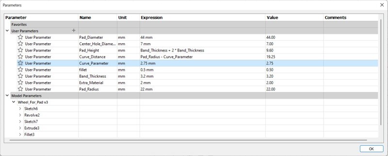
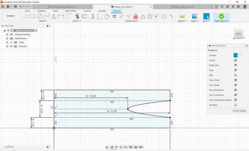
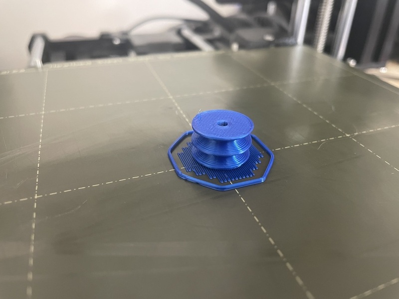
After using the revolve feature, this was the final result
I then exported the image as an STL similar to the rod and printed it out.
The Fusion embedded image is an updated version than what is shown exported. I had to change the design later in the project
Once it was printed it fit pretty well into the rod but I needed it to be a more smoother so it would put less stress on the DC motor, so I used a drill to file it out.
Gear Piece
A similar concept to the gear pad I had to create a divot for the band, but this time I needed two because the gear piece would be rotating both sides and I was afraid that the friction of one band would stop the other if both pands were connected. I also knew that the revolve feature would be the best option concidering the gear pad. I also needed to create a hole that was press fit with the DC motor metal rod. I had the measurments and I made sure to make the hole a little bit bigger so the filament would be accounted for.
I ran a sketch with the same idea as the DC motor except multiplied twice
then I had to create the hole which was simple. Using parameters I was having some difficulty with changing values so I added some constraints and it fixed the bug.
Finally I sliced the image and printed it
Putting the Components Together
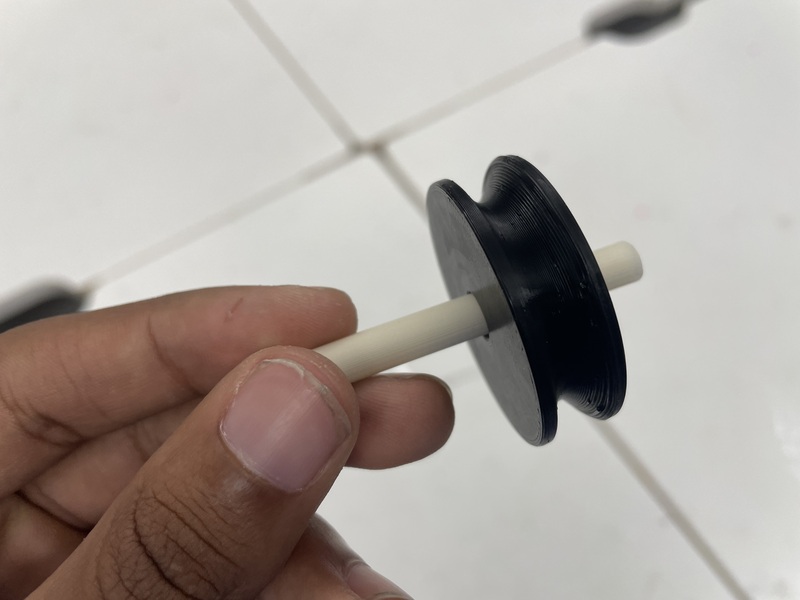
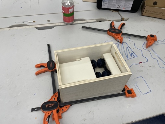
I mentioned ealier that I had to use the drill to create some bigger holes but now that it was finished I began putting the pieces together. I had already placed the DC motor. Then I connected the rod and gear pad together with a mallet. I got some hair bands and tied the pieces together and suprisingly the gear rotated! I tried to use the bantam tools milling bands but those had too much tension.
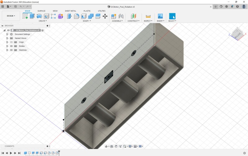
I then added the second gear pad and the machine rotated both pads!
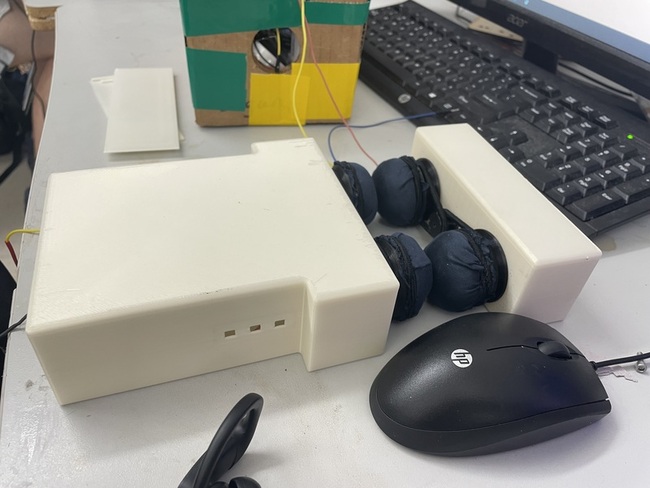
Wire Case Pad Holder
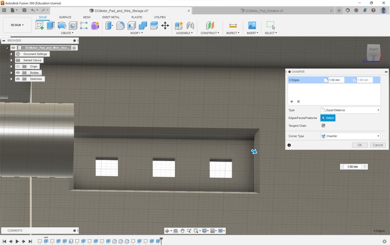
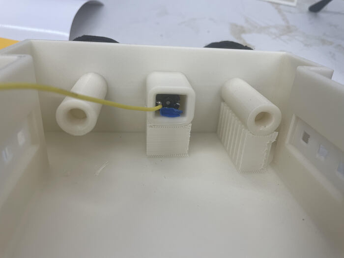
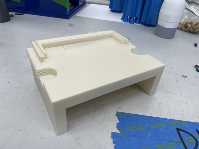
This was the second main component of the cleaner. This would store the wires while also being a place for the pads to clean the opposite side of the glasses. I copied the holder file from the previous design and pasted it onto this new one. Then I went into the Fusion 360 timeline to add some extra peices to the extruded sketch. I changed the length size and extended the width so that it mached the width of the glasses. I made sure that their was a hole for the DC motor wires to extend out. After that I did some shelling. Finally I put placed a small hole for the OLED display and RFID to stick out for the wood base.
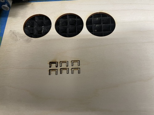
I then needed to add a place for the LEDs to go into. I wasn’t able to get the UVC leds in time for the project, so I have to substitute them for normal blue LEDS. I placed some holes close to the front of the glasses, and used the chamfer tool to create a hole that I could place the PCB that I was going to mill.
I also realized that I had to make the length of the wire case a little smaller because of the filament not being exactly the distance I would need. Since I changed the values, the holes for the motor and gears were a little offset but it was a minor difference.
After that I added some fillets and my design was finished.
I sliced it then printed it out
I made the DC motor hole a little bigger concidering I had to drill it last time. Unfortunately, I made the hole a little bigger than expected and the hole was loose. The print was 15 hours and I couldn’t afford to print it again because of the time investment. So I just went on with it and used magnets to hold it in place.
Adding the Pads
I then had to think of a way to add the pads and I realized a mistake that I made with the rods. Because they had the tab I couldn’t attach the cloth to the rotating gear correctly. I had to sand the 3D rod down then re-insert it, but then I ran into another problem. The origianl purpose of the tab was to hold the gear down but since I sanded it down nothing was planted in place to hold the gear down. I figured that the glasses would have to hold it down but it wouldn’t be secured as I would like it to be.
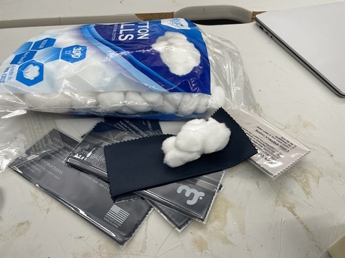
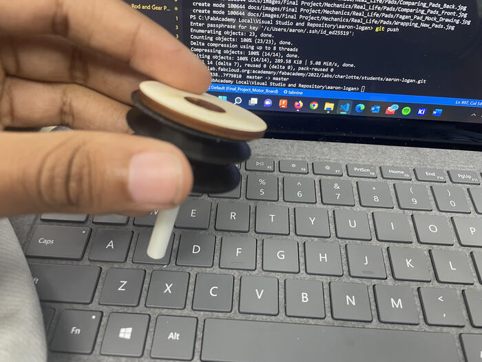
I also had a problem with actually creating the pad, I needed to fit the circular microfiber cloth onto some cotton balls both of wich I got from [Amazon.com] (http://www.amazon.com).
I was struggling to get them on, experementing with duck tape, and some glue but I couldn’t get the best adhesion. Here is one of my test videos.
I realized through further experementing, that I needed to laser cut circles as a reference to hold the cotton in place so the microfiber cloth could wrap around the cotton and laser cut frame.
I used my computer controlled cutting) documentation for laser cutting. I created the SVG file with the dimensions of exactly the diameter of my pad diameter. I also made sure to account for the kerf. I printed the file on the laser cutter and printed it
Again I was still struggling with the padding. Then after talking with Ms. Dhiman she recomended the idea of cutting flaps on the circular pad then gluing them onto the wood piece.
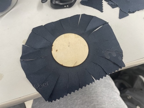
This idea would work but I was cutting too much of the microfiber cloth away, so I laser cut a larger circle as a reference to cut towards
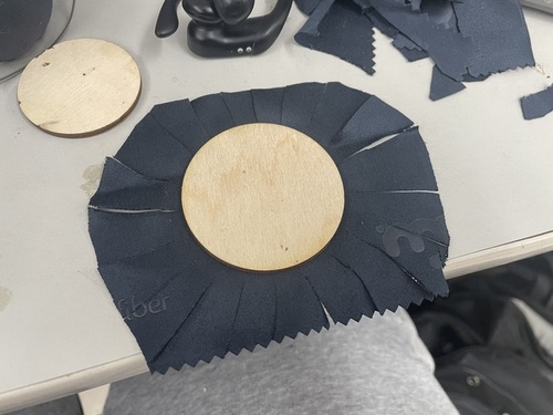
With this reference I was able to cut cleanly and as I went on I improved in the cutting and getting the exact dimensions correct. Though the hardest part was super gluing the piece together. I would get the glue on my hands and it was pretty annoying but I had to do it.
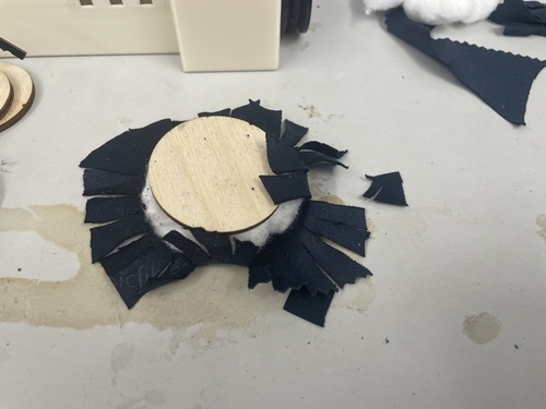
Also with the cloth being flexible it was hard to get a grip on it as I tried to glue it but I eventually got it.
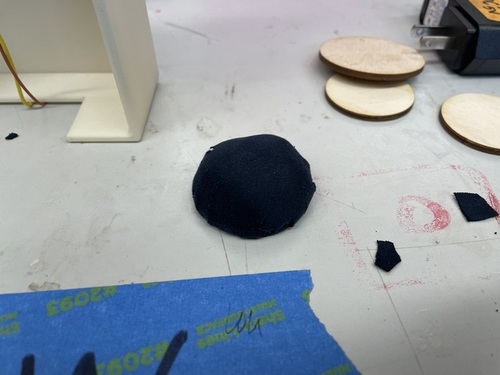
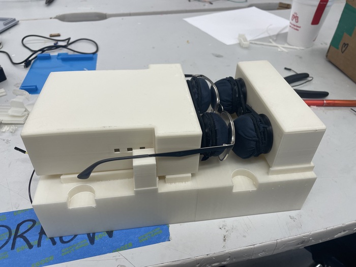
Once I was done with this I used some more super glue to connect the pad to the rotating piece, and ran the motor and it turned but with a little issue. The pad was very close to touching the ground and some of the cotton would extend from the pad to the ground causing some friction would would slow down the motor and in some cases it would stop completely, but it could still function.
I added the pads to the other part of the cleaner and tested to see it and it worked again with some issues. The pressure from the glasses put a great amount of strain on the DC motors causing one pad to stop rotating. I eventually sovled this problem but their was still two glaring issues that I needed to address. I was using super glue, and the pad wasn’t connected to the machine. I was concidering just moving on but after a great idea from Dr. Fagan. I could combine the two components. I could have the wheel but also add another layer to wrap the pads around with another hair band. He drew up this mock design to help me understand.
I went back to Fusion 360 to redesign the wheel. All I did was go back in the design timeline add an extra layer for another pad to wrap around. The software did the rest and calculated the rest of the remaining features. Though I still had to go back to add the fillets. This was the final design; it’s pretty similar to the gear piece.
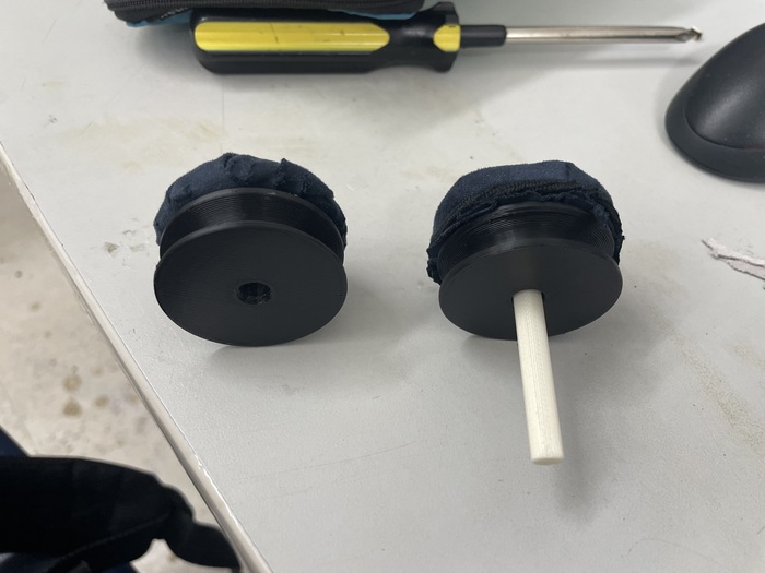
I attempted to put the padding on, and it was much easier. When I used the super glue design it took me about 30 to 45 minutes per pad. With the new design it took me at most 10 minutes. Their was a major issue that I was able to solve; the cloth would wrap around the rod tab. As the motor rotated around, the cloth would be caught under it, causing the pad to slow down. The way I solved this problem was Laser cutting a 1/8 in piece of wood that would wrap around the pad, but this one had a hole in the middle so the pad could rotate no problem.
After that I did some wrapping and this is what I got
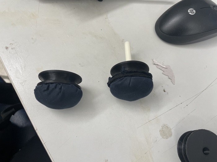
When I tried to insert the pads with the rod already inserted I had problems because the rod was press fit.To solve this I put in the rod and gear pad in first then I attached the microfiber using the same technique of cutting a circle and some slits. Once I did that I was done and the pads were attached. Their was another problem, I put too much cotton in the outer lens pads which caused them to have some friction with the ground. To solve that, my final design is going to elevate the pads a little bit, so that they don’t touch the ground but still have contact with the glasses. Which is what I designed next
I wish I could show a video but I ran into a little problem with the wire and the DC motor. On the big case, the wire ripped off. On the small case, the DC motor gears came loose, it still works, but I’m afraid of it jamming up.
Case Holder
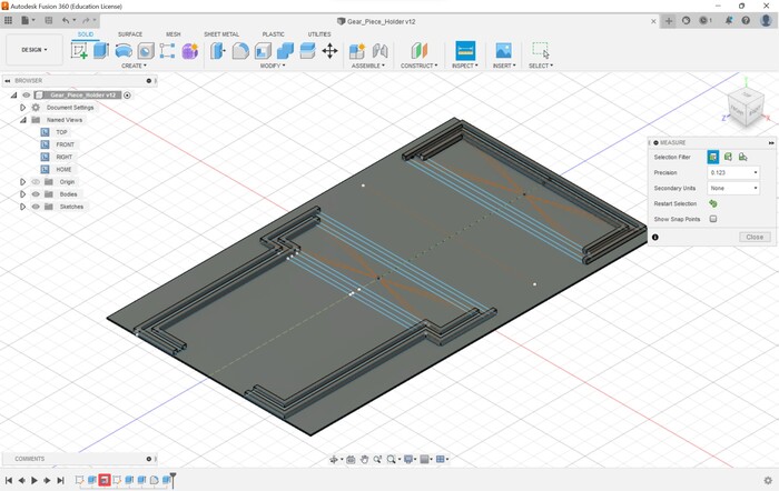
This part was a lot of math and sketching. First I had to determine the thickness I wanted the gap to be and the distance apart the cases would be from each other. Since the pads are removable this part doesn’t matter as much, but I still needed to account for this becasue I wanted to decrease friction as much as possible. In Fusion 360 I created a sketch that would be the total length and width of the entire case. The case would also act as wire storage and be removable so the user can hook up wires if something goes wrong.
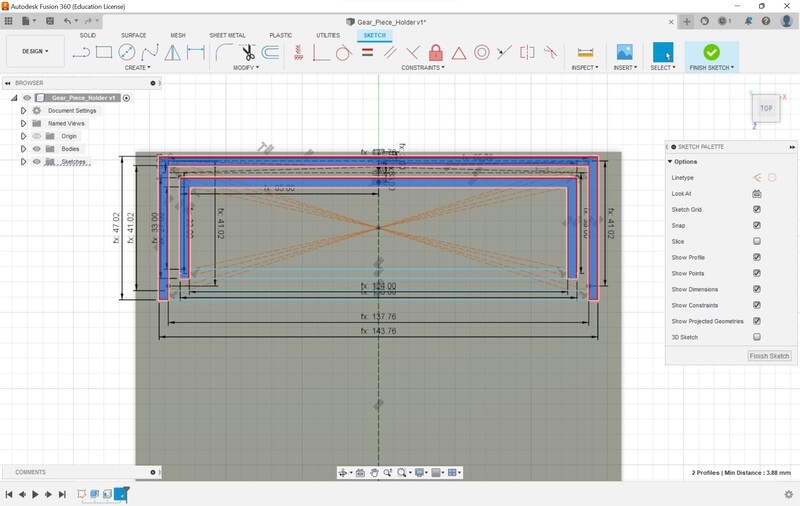
After making the case the total dimensions I had to measured the distance between the two corner ponts of the cases, and I made this a parameter incase I had to change that. The best way I came up with creating the pocket for the case was to create 4 rectangles. Each of the rectangles would be centered and a single point and I would use lines to seperate the rectangles into the particular piece that I needed. I needed 4 rectangles because I needed two gaps that would be extruded to create the pocket that I needed. I also had to take account for the thickness of the extruded piece and the thickness of the gap. This was a lot more complicated than I anticipated, it required a lot of math as you can see from my scrap paper image.
I measured the dimensions of the outer part of the design, then the inner part to get a value that would create a gap that was right in between the design. After a lot of designing, tinkering, encoporating construction lines, and constriants, I was able to get my first design. To design it initially, I had to use the 2 point rectangle feature, then I switched it to center rectangles so the parameters would work from the center. I then added some lines that would cut the rectangles to the shape that I needed.
I then mirrored the design from a construction line that was half of the distance I needed the pads to be. I then deleted all of the mirror constraints becasue I needed to change the larger design. I had to change the dimensions of the larger case a little so the glasses could fit, likewise I had to change the holder for the larger case. Since I used parameters I measured the difference between the two cases and I implimented that into the design. After, I added some constraints and some extra lines to cut the design into what I needed.
The larger case is broken up into two parts so I had to measure the difference between the two components. Once I was done with that, I extruded the parts I needed, then added some fillets and I had a prototype. Mr. Dubick recommended that I make the print a mock version so if I messed up a value the 3D print would only take one hour and not take five. The final thing I did to make sure I could edit parameters was I used the lock constraint to lock the holder close to the edge in place, so the only piece that would move would be the larger case holder. I finished up the first test design and exported it to see the results
Surprisingly, it was secure. I have to make sure to add the holes for the wires to fit through.
Even for the other design it fit decently. I noticed the extra space on the sides and I had to trim that down so the design could fit. Also, since I printed a thin layer of filament, the design was flexible and was bending when I attached it. I made sure to shorten the distances of the design.
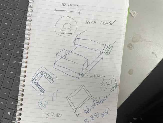
I went back to designing and I added a couple of more features. The measurments that I made earlier helped the design stay consitent though their was one problem that I faced. The slot thickness I wanted was 3.88 mm, but at some points of the design the slot thickness was 4.010. I doubled and triple checked the math and couldn’t see where the error was. I had to skip this problem because I expect the distance to be negligible, I hope. First I extended more the pocket for a more secure connection on the larger case. I made sure to shorten the tab distance. I also added some elevation to the actual pocket, to account for the pad friction. Then I added some fillets and my design was almost finished. I wanted to do one more test.
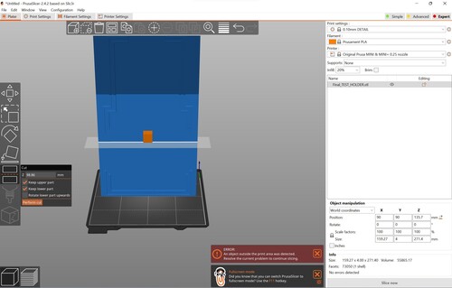
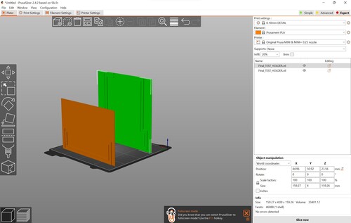
I also had to split the components in PrusaSlicer because it was too large. I saved each part as a separate GCODE file by using the hide feature. Then I printed out the file.
I printed the design and I tried to insert it but unsurprisingly it didn’t work. The holder was too large for the holes to fit into. If I’m being honest, I was pretty frustrated. My designing was horrible and I knew it and I had already spent 4 hours trying to create it. I was contemplating just restarting the design but I know that the smaller case design works well, and I need both components to be together so their was no restarting completely. I did however delete the whole large case design to clear the mind. I felt like trying to tinker the design would be harder than just restarting.
I then had a great idea that would be much easier to use. Instead of trying to create a pocket with for the corners, why not just ignore the corners completely and only design pockets for the vertical parts of the design? This would be more flexible and easier to design. I went back to the holder design and deleted a bunch of the old parameters and created some new ones. I had to measure the offets for a lot of the components of the larger case. Instead of using large rectangles to create pockets that I would extrude, I would create individual rectangles that I would extrude to act as the pocket and I could control a lot easier because of the minimal amount of contraints. I needed a group of 3 rectangles connected together; the outer two would be the pocket and the inner would be the elevation to account for the pads. I came up with this design
I then measured the offset from the upper tab to the wire case tab then created another group from their.
Similarly to the original design I exported the STL to test the dimensions of the design. Again using the PrusaSlicer cut operation.
I had to change some of the offset parameters but I was able to get it to fit nicly. I also realized that this made the large case adjustable in case something goes wrong with the pads.
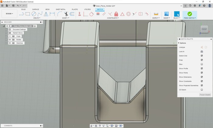
I had to make a couple of more adjustments to get the railing secure. Then I realized that I needed to use a create a pocket for the flexible holders to be stored. I went back to the sketch and measured the distance that I wanted the holders to be from the pads. I added an outer and inner square pocket so I could extrude the hole. For some reason the shell feature didn’t work properly so I improvised.
After adding the pocket, and making the adjustments for the dimensions of the rails I was finished and I printed the design. Once it was done I attached it to the case and it fit perfectly.
Their was one minor mistake and that is the pocket for the flexible holders were flipped around. I changed the parameters on the design and that issue was fixed. I was about to print it then I got some helpful advice from Mr. Dubick and Graham Smith; use chamfers to help secure the pieces. I made sure to add some chamfers to the rails but when doing a test print the chamfers didn’t even print because they weren’t large enough. When trying to increase their size I ran into some errors with the height of the rail. I added some more height then increased the chamfer distance and it worked. After I added some fillets to the chamfer
Then I also recived some more helpful information from Mr. Budzukowski in regards to how the 3D printed pieces will fit in the case. I needed to create something to allow a person to grab the pieces to access the wiring. He recommended that I create some finger holes so someone could lift it up. He created this image as a reference
I added those to the design by using the 2D fillet tool on 2 point rectangles then extruded them downwards
After that I increased the height of the whole design then shelled out the middle for wire managment and the holder was completed
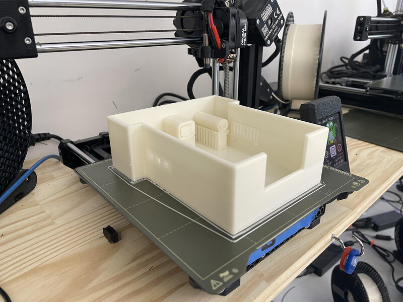
I exported this design as an STL then put then used the split tool similarly to the last time. I was experiencing some error with the slicing because of how the railing were. I didn’t want to print the design upside down becasue then I put supports in the railings and I didn’t want to mess with those. Though if I print it right side up then I would have to use a lot of supports. I was concidering using the latter idea becasue it would keep the railings as accurate as possible but I was getting some errors with the supports. Supports would only show up in the hole and the outer shell leaving the middle part wide open. I knew the filament couldn’t travel that large of distance so I was having trouble editing the support settings. Graham Smith attempted to help me with the supporting errors but we couldn’t find anything so I decided to print it vertically. The image shows 2 days but the actual prints were 18 hours and 22 hours
I printed out the designs and they came out beautifully
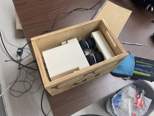
I combined them together and everything fit!!!
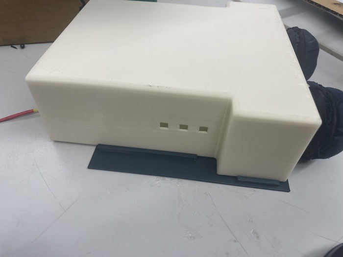
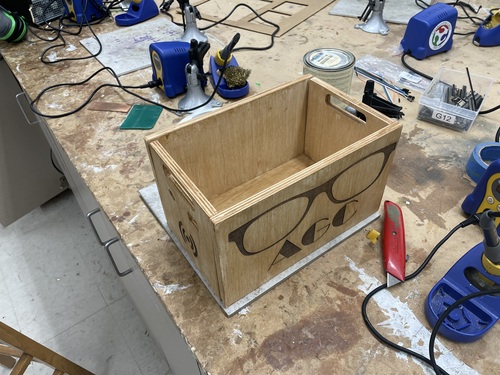
Outer Wood Base
Fusion 360
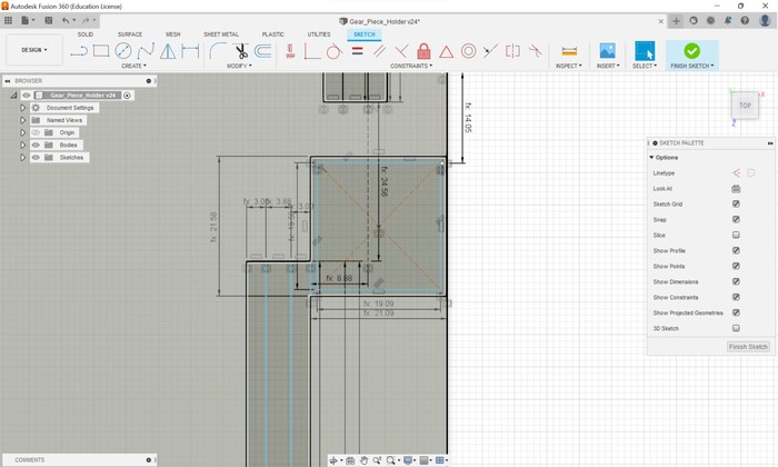
The final step of the project was to create the wood base that would hold the pieces together. Talking to Mr. Dubick he recommended that the easiest cut would be a rabbet cut. I had to doe some reaserch on exactly that was and I came accross this Youtube video. He was using a table saw for the wood instead of a CNC machine. I wanted to find ways to encoporate the CNC machine and I came to the idea that I could make the rabbet cuts a pocket cut while the outer cut a profile. I had to use my Computer Controlled Machining documentation for a reference on how to use our labs Shopbot. I was using Fusion 360 for the design so that is what I was going to use now. I created a sketch and last time I made the sketch on the xz plane and when I had to export the design as a DXF it was wrong, so I made sure to create the sketch on the xy plane so I could export the design as a DXF to Corel Draw then export the design as an SVG. Per usual, I measured the dimensions of the design in total. I made sure to add a little more space for the RFID, OLED, and micro USB port. I created the rectangles that would be the size then I used a construction line to measure the size of the rabbet
Then I had to add some handles for easy transportation. I made sure to add some fillets for this becasue this is what I was going to be grabbing all of the time.
Then I repeated the handle design for the other piece. I then had to make the long edge of the box, but since I already had parameters I was set and the creation of the piece was easy.
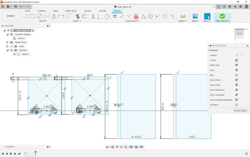
Finally I created the bottom piece and made sure to account for the distance the rabbet would take off.
Once it was done I exported the DXF to Corel Draw
Corel Draw and Aspire
Once the DXF was exported, I checked the measurements and then saved it as an SVG. I loaded up the file into aspire and I was experiencing some issues. The vectors weren’t combined correctly and the pocket cut would select the region that I needed. So I went back into Corel Draw and had to figure out a way to troubleshoot the problem. After going through a couple of ideas and redesigning I came to the conclusion that I needed to create a seperate rectangle that was a little smaller then just sand it down once the cut was finished. With this approach I was able to get the print ready for the Shopbot but I ran into some more problems with the machine. First, the z-homing was not correct.
Mr. Budzukowski helped me troubleshoot the problem. Apparently the Shopbot has two ways to home the z-axis, either using bar (0.1 in off the surface) or a build plate (which is what we use at 0.5 in off the surface). The settings were set for the bar which was causing the error. Thanks to him the machine was almost ready to cut, then I ran into the same issue during CNC week. The estimated time for the cut was about 40 minutes when I was confident it should be no more than 20 minutes. Remembering this issue, I looked back through my documentation to find that the error was the spindle feed rate. It was 50 in/min, instead of it usually being 250 in/min. After changing this the final cut was estimated to be 12 minutes total. After that was finished I ran the cut and this was the result.
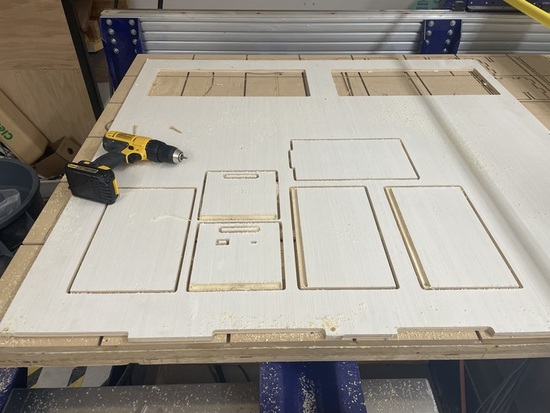
Similar process to last time I had to sand down the tabs and the wood so that it was comfortable to touch.
Once the sanding was done, I was ready to assemble the pieces together.
It was decently put together but their was one major problem, the box wasn’t completely rectangular at the top. The long sides weren’t long enough to get all of the sides but I do have a video of it working completly.
Since the wood was already cut I decided to just use the table saw to create the correct pieces of wood. I wasn’t used to using the table saw however a fellow Fab Academy Student Jada Greene helped me a lot through the process. I was able to get the correct pieces then I sanded them down again. Then I ran into a predicament, how would I paint the wood. Their were two options that I could explore.
- Use real paint, but he downside was that the wood wouldn’t look natural.
- Stain the wood, but since I was using plywood then it would be hard to stain the edges.
I initally attempted to stain the wood. I used these videos to help me understand the process.
Mr. Dubick said that I should usd a test piece of wood, which is exactly what I did. I came this far and the results looked good, but again it was plywood, so the edges didn’t look too great.
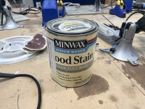
With this idea looking terrible I was concidering using paint, I didn’t want to but it seemed like the best option to darken the color. As I was about to test on another piece of plywood, my instructor Dr. Taylor had some other ideas to help with the staining. He tried multiple methods and came down to one that used simple wood staining. The stain we used is below
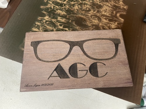
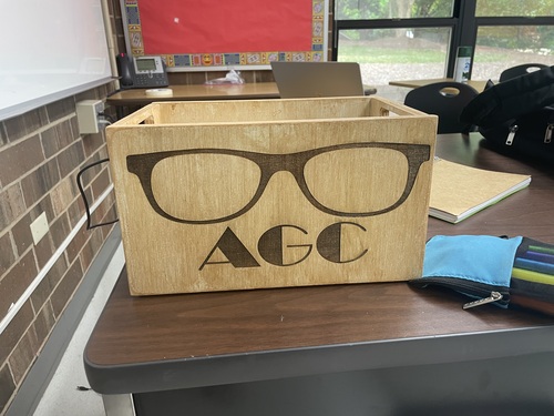
He said because it was plywood, this would be the best option. Dr. Taylor also made sure to tell me to not stain the rabbet parts. Since the wood glue that I was using wouldn’t work because the stain would seep into the wood leaving no room for the plywood. Before staining I made wanted to raster some designs on the sides, concidering they were pretty large but didn’t ahve anything on them. I used the laser cutter deep engrave preset that our lab has. After that I looked up some images to put on the box. I wanted to encoporate a logo and I decided on AGC standing for (Automatic Glasses Cleaner) or (Aaron’s Glasses Cleaner), which ever sounds better. Then I added a glasses svg that I found here. Then I went into corel and used a fancy text font to complete the design. After that I sent the print to the laser cutter and let it work its magic. It was the test logo from ealier but this time to scale for the print.
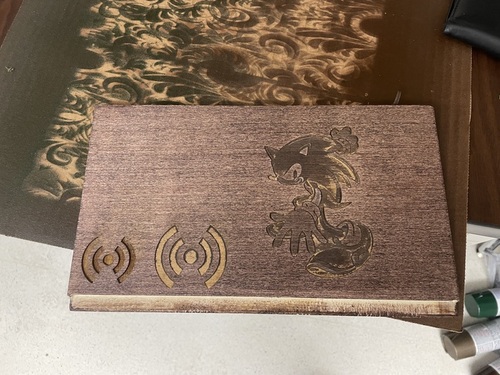
Then I had to laser cut a RFID logo, I got the image from here
Finally I added a sonic adventure 2 SVG to the other edge and a signature for the other long side. Now that I was done with the laser cutter it was time to stain the box. All of those engraves were on the original stained wood from earlier. When adding the stain I made sure to avoid the rabbet cuts. Then, as I was about to add the wood glue, because of how I designed the box, I made a mistake. The side pieces of the shorter side needed to be sanded, I didn’t think I needed to put wood glue their but because I didn’t add a rabbet I would have to add glue. I had to sand down these regions to remove some of the stain. After that I applied the wood glue then sealed the box together.
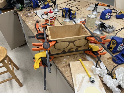
I had to wait a little bit for it to dry. Again, huge thanks to Dr. Taylor for guiding me through this process.
The Finishing Touches
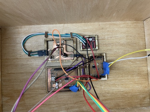
Wire Managment
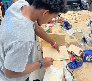
I wanted to organize the wires on the bottom of the outer base. To do this, I took inspiration from Nick Niles. He used 3D printed pieces to press fit his PCBs and compontents in one place, while also using little hooks to hold the wires down. I plan on doing the same thing. I knew I didn’t have time to 3D print a design so I went to the laser cutter using 1/4 in plywood I would cut a rectangle with an inner pocket that would be press fit for the PCBs that I had. I had to make some measurments and I put those into Corel Draw, making sure to account for kerf. Once this was finished I printed them out and they fit first time surprisingly.
I then went home to start the managment. First I planned out exactly where the pieces were going to go then I used super glue to hold down the wood pieces then placed the PCBs there. Then I implimented Nick Niles’s idea with the hooks. I went and loaded up Corel Draw then created a simple cut.
I then attached them to the base of the wood and these were the results
Final Assembly
Now that the communication wires were set it now had to connect all of the power and ground wires. This process was easy because I had the commong power and ground board though I did recieve som good advice from Mr. Dubick in regards to the power and ground board. I should’ve put a capacitor, incase their is a voltage drop from the outlet. I made sure to take note of that for possible future improvements. Once the power wires were successfully connected (which took a surprisingly amount of time because the wires were too short) I checked to make sure no wires were showing besides the RFID and OLED wires, and none were.
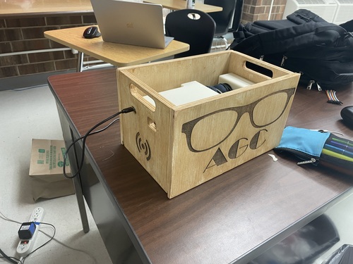
I turned on the machine and everything worked!!
Post-Project Questions
Processes Used?
| Process | Application |
|---|---|
| Computer Aided Design | Design 3D Cases and Prototype Modeling |
| Computer Controlled Cutting | Laser engraving wood case, laser cut pad extension pieces |
| Electronics Production | Milling, soldering, and programming Satshakit and DC Motor Board |
| 3D Printing | 3D printing cases and holders |
| Electronic Design | Designing DC motor board and power board |
| Computer Controlled Machining | Shopbot outer wood case |
| Embedded Programming | Programming Satshakit and ATtiny1614 |
| Molding and Casting | Molding flexible holders |
| Input Devices | Encoporating RFID reader |
| Output Devices | Using DC motors and OLED display |
| Networking and Communications | Creating an I2C bus between Satshakit and DC motor board |
What Did I Design?
Besides the Satshakit, I designed everything. I created the DC motor board. I also had to design the inner 3D printed cases and the outer CNC box.
What Parts and Systems Were Made?
For the eletrical part of the project, I had to make the power board and the DC motor board. The Satshakit already had documentation on how to use it. For the Mechanical aspect, I had to design all of the components. I designed, both DC motor cases, the case holder, the wire managment hooks and holes, and the outer wood case.
What Questions Were Answered?
Looking back at Applications and Implications I asked the following questions
- How well do the glasses actually clean?
The cleaner cleans well, the middle part of the glasses is clear. Though their still is room for improvement. Since the pads rotate with a circular pattern, the cloth can’t reach the edge of the frames. To improve upon this, I’m going to use an elipsoid pattern to reach the edges.
- How well does the UVC LED sterilize the frames?
Since I wasn’t able to get the UCV LED’s in time for the project due date, I don’t have an accurate representation of what the UV light would do. Though looking at the range NM range of the LED, it would kill any bacteria that is vunerable to that wavelength
- Can it act act as a place to store someones glasses?
Yes, the glasses can be stored their for as long as possible and be cleanned multiple times if necessary.
- Are the pads replacable?
Yes the pads are replacable. The components are press-fit into the holder and can be removed with some force. Then someone can remove the press-fit rods from the case and create new pads using my design files
- Can it clean any pair of glasses?
No, the cleaner works best for circular glasses. For more oval or square shaped glasses the pads cannot reach the edges.
What Worked? What Didn’t?
What worked
- The pads rotating with hair bands
- The cleaning of the glasses at the center of the lenses
- Creating a second layer on the 3D printed pad holders for the microfiber pads that would hold the gear rods
- The flexible holders keeping the glasses secure and in place
- Making the pressfit elevated case to hold the DC motor cases in place that allows for adjustable movement
- Creating an OLED timer
- RFID sensor activating every component
- Using the Satshakit for the sensors while creating a board only for the DC motors
- Using rabbet cuts for the outer box
- Using the CNC to create rabbet cuts for the outer wood case.
What didn’t work
- Trying to network 3 ATtiny1614 microcontrollers together
- Using superglue to connect the microfiber cloths to the pads
- Creating the elevated case holder so that it press-fits around the entire large case
- Press-fitting the components a little too well
How Was It Evaluated?
According to my Applications and Implications documentation the cleaner evaluates pretty well. The pads clean the center of the lenses but can’t reach the edges of more square shaped glasses. I wasn’t able to get the UVC light in time for the project but it would kill any bacteria in that range. The pads and components are replacable. The wire managment was stellar also, it was even acknowledge by the head instructor of Fab Academy, Neil Gershenfeld. If you click on our presentation video and hit play you can see!
What are the Implications
An inexpenisve way to clean and sterilize ones glasses and also hold them in place. Some ideas for the future would be creating a mass cleaning operation to clean and sterilize protective glasses for science classrooms or labs. Also it can be used at someones home for easy storage. I know that I am always misplacing my glasses and this is going to be extremely helpful!
Project Files
Here are my project files