12. Output Devices
Assignment: Add an output device to a microcontroller board you’ve designed, and program it to do something
Using a DC motor
I wanted to use this week to help me further my progress for my final project and for that I would need a DC motor. My DC motor is different because it converts the rotational kinetic energy into torque. I want to power it by using an outlet and for that I would need a power brick.
Calculating Power Consumption
This link was helpful
The specs of the 6V and 0.45A, so I would need a power brick that has a voltage close to that and enough amplitude to provide power. Since I was using a DC motor I had to use this motor driver. Thanks to some help from Dr. Harris I realized that to power the motor I would have to plug in two pins from the microcontroller into the “in” ports and the power and ground wires from the motors into the corresponding “out” ports. I would then power that motor using the power brick in the power and ground pins on the driver. There was one problem I ran into, there wasn’t a place to power the microcontroller too. This motor driver I was looking at previously has multiple ground pins, a VCC for the microcontroller and a VM for the motor meaning I could run everything through the driver using one power source. However, the lab didn’t have these drivers, they had the ones I mentioned earlier. Because of this, I would have to run everything through my milled board. There was one danger, if I ran the power through the microcontroller, I would fry it and I had a tough time trouble shooting this. I could’ve easily troubleshooted this by creating two power sources, one for the controller and the other for the motor, but I wanted to keep the power consistent from the same place. I was initially confused because I thought I could only have one VCC and one ground trace and I would have to run it through the microcontroller to power it, which would fry it. I realized thanks to Dr. Harris that I could have two power traces connected to the same pin, the voltage would be the same for each trace, likewise for the ground. So on my schematic I would have to have the power and ground diverge into two separate headers for the driver.
Controlling the Driver
This link helped
I would have two pins connected, one that is PWN (with analog write) and the other that is a all-time high or all-time low. The motor only turns when the pins are at alternate voltage. To move the motor, I will have to set one pin as all time low, then use an analogWrite function for the other pin from (0-255) and this will in tern set the amount of power that the motor will receive that percentage of power however there is a catch, and this is due to how you set the other pin. If the constant pin is high, then if I make the analogWrite function have a value set at 20 that means 80% of the time it is at full power. Because that means the power is always high except for 20% so this equals out to 80%If I set the other pin to low, then if I make the analogWrite function have set at 20 that means 20% of the power comes on. Because the graph only spikes for 20% of the time. A motor driver works by sending a power signal which turns on a switch that sends the voltage from the power brick into the motor, and the driver that I was using had one side that is low voltage (from Arduino) and the other side is high voltage (power brick). The image below helped me when it came to how analogWrite functions work; it shows an example of an all time low with a function at 20.

Testing the AnalogWrite function
I wasn’t used to using this function, and I wanted to have some experience before I use it on my motor. So I practiced on an Arduino MEGA by making the built in LED fade in and out. I used our group documentation to help me write the code and I came up with this
const int ledPin = 13;
//const int pwmval = 128;
void setup() {
  // put your setup code here, to run once:
  pinMode(ledPin, OUTPUT);
}

void loop() {
  // put your main code here, to run repeatedly:
  for (int i = 0; i < 256; i += 5) {
    analogWrite(ledPin, i);
    delay(80);
  }
  for (int i = 256; i >= 0; i -= 5) {
    analogWrite(ledPin, i);
    delay(80);
  }
}
KiCad
KiCad Schematic
I used my earlier documentation on my button blinky to help me with this. I would be using the same components as last time
- ATTiny412 Microcontroller
- 1UF Capacitor
- 3 Pin Header
- 330-ohm Resistor
- Red LED
- Button Switch
For this week I knew that I didn’t have to include an LED or a button, but I wanted to because why not. The LED would act as a power indicator by creating a closed circuit from power to resistor to led to ground, and the button opens more possibilities for programming. The only thing that I would have to add would be is a
- 2 pin horizontal header for power
- 2 pin horizontal header for motor control
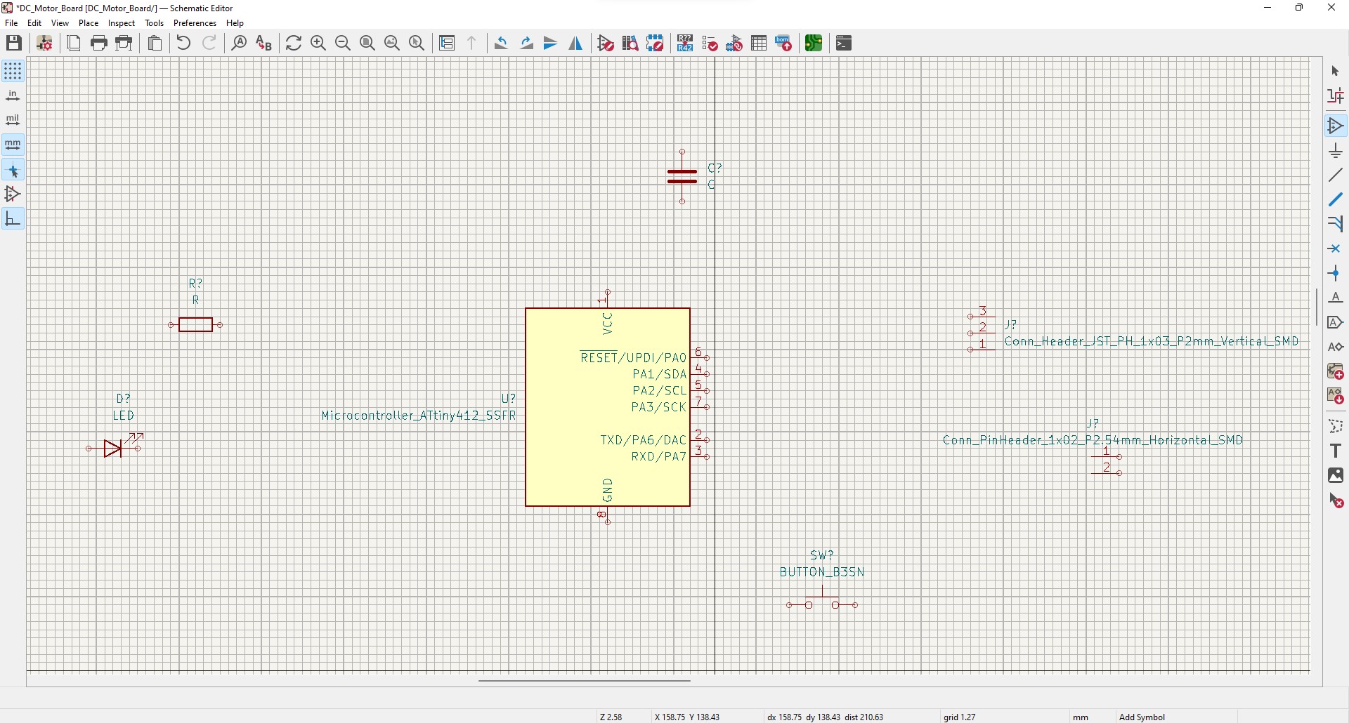
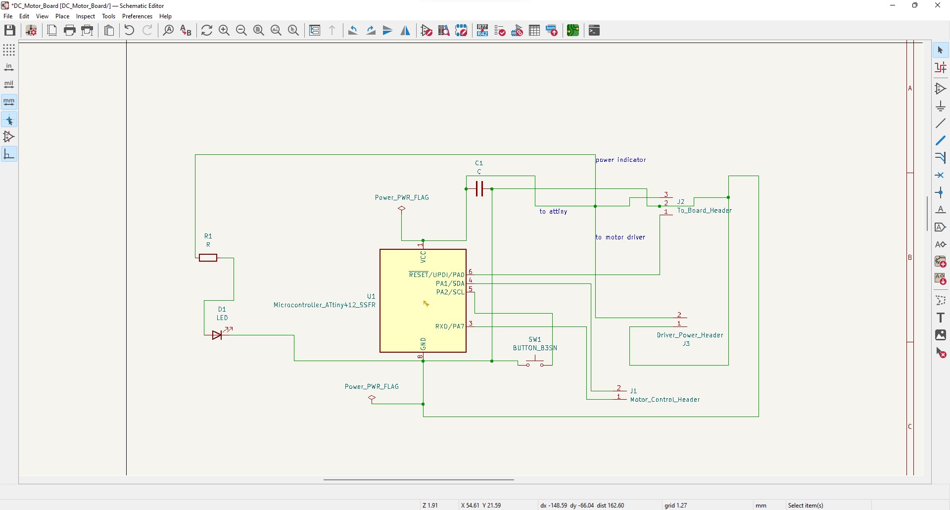
I began connecting the wires in the schematic editor. It was the same process as earlier however this time I had to check the pinout to see which pins supported PWM, the only ones that didn’t were PA0 and PA6.
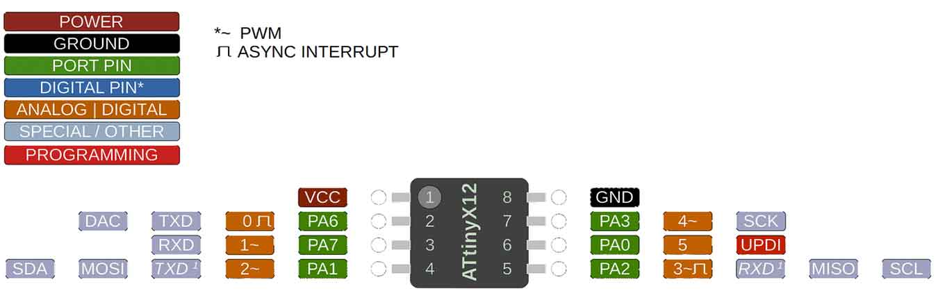
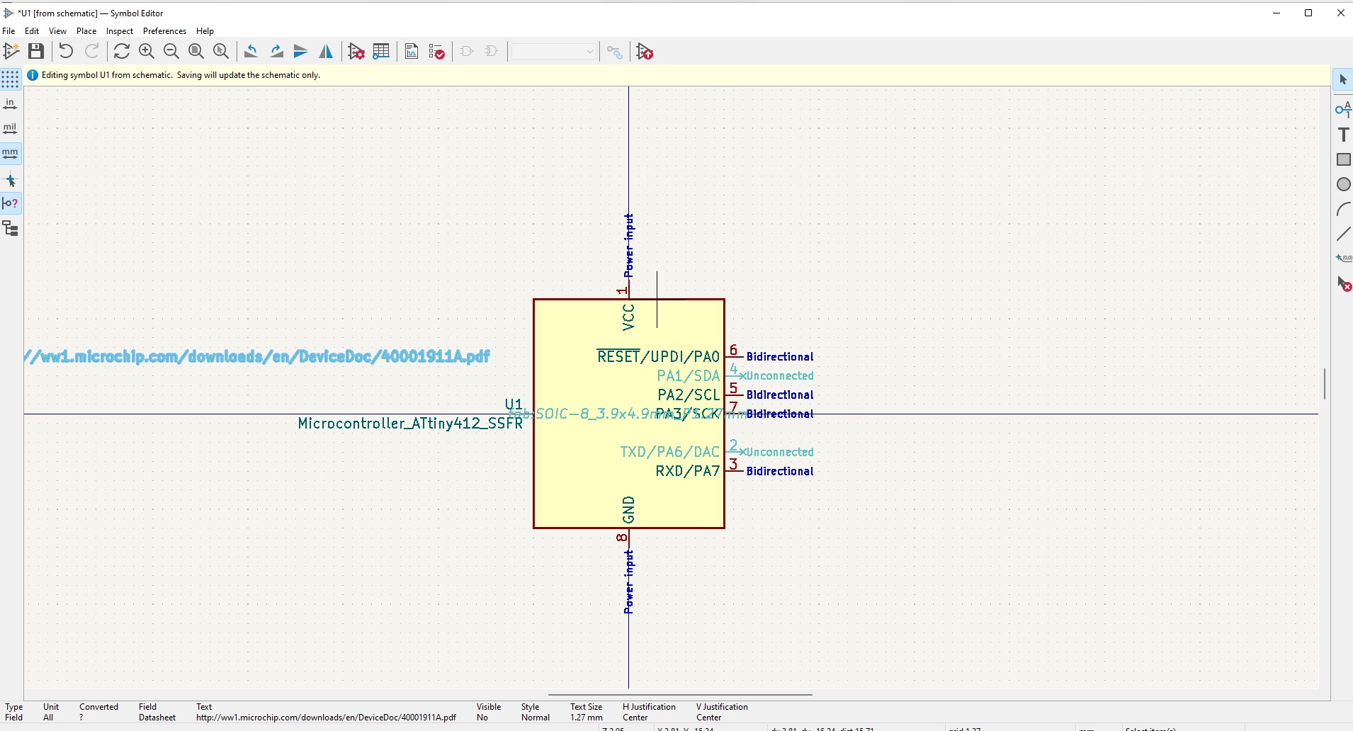
I made sure to not connect them when adding wires. I had all of the wires connected at first but I didn’t think of which side on the controller were the pins. I didn’t want to have the motor controlling pins be on opposite sides and I also had to take in account for the PWM. I had to do a lot of rearranging, but I eventually got the right design. I had to edit the ATTiny412 symbol so that the pins I wasn’t using were turnned off
I finally put in power flags so I wouldn’t recieve any powering errors.
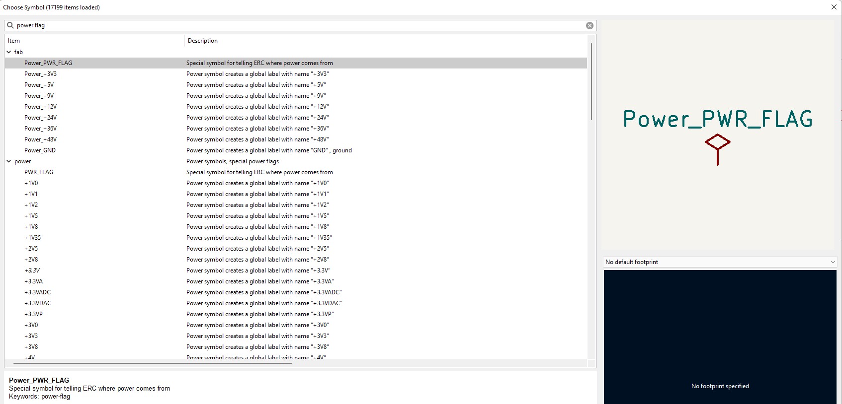
Then my design was done.
KiCad Editor
I brought in the components, and I realized something quickly, I forgot to add a footprint for the resistor. After I fixed this the next step was to organize. I spaced out all the components and stared labeling the pads so I wouldn’t be confused later. I went to edit the constraints, similarity to my earlier documentation.
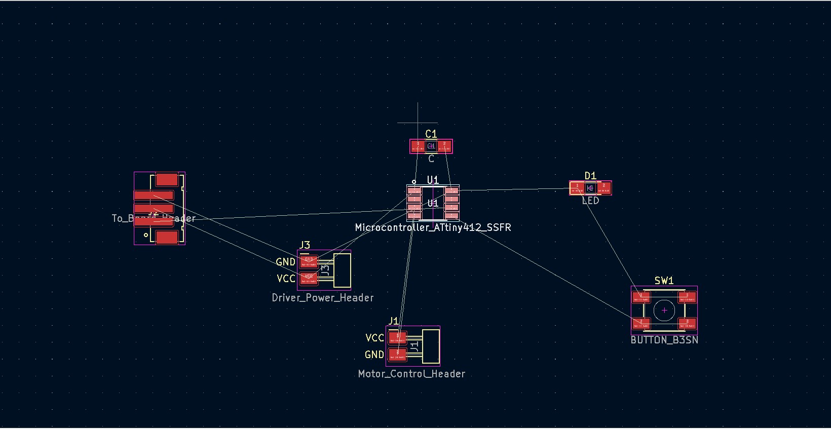
The process was simple; connect the wires together. Before connecting them, I went into the board manger and set constraints for the trace width and clearance, I used my previous documentation for that. I will say that it was difficult to track where the VCC was going sometimes. I needed the power to split 3 ways, but the software kept trying to get me to connect them together in way that would be dangerous. Though after I connected them the way I wanted and ran the ERC (electric rules checker), the design was fine. I went through multiple designs and on multiple occasions I would have to go back to the schematic editor to change where certain pins would go.
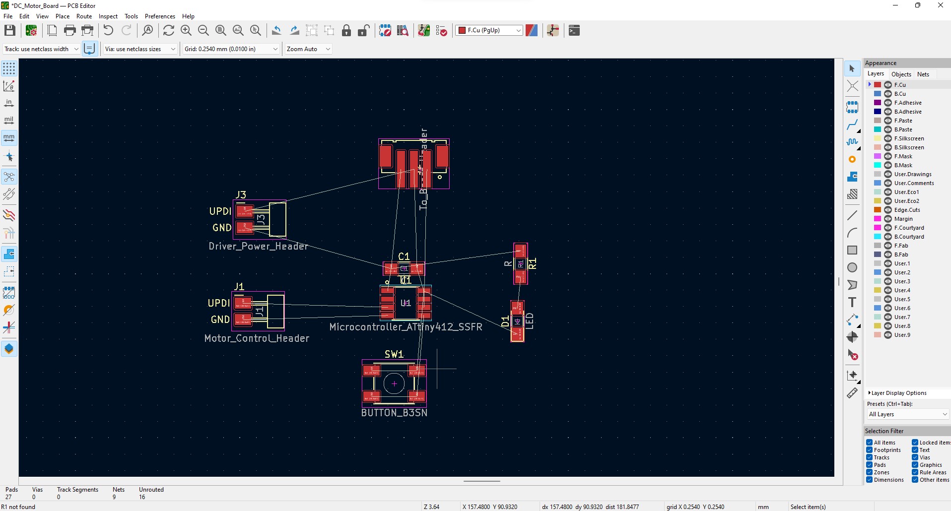
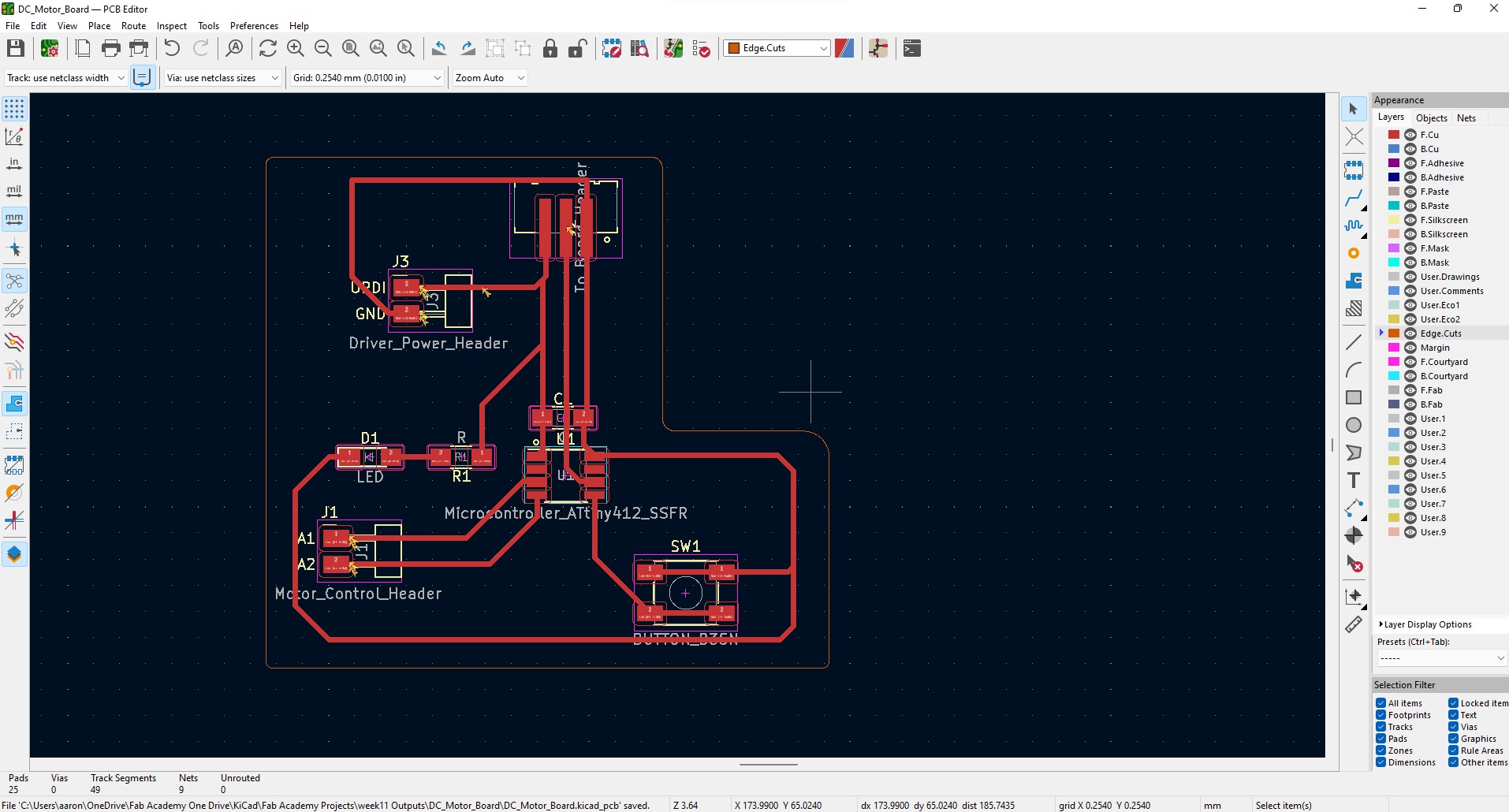
The final step was to create a cutting edge for the machine. It clicked on the Edge.Cuts layer and drew out a box that wrapped around the components. I decided to round the edges using the arc tool so it would be easier to grab.
Exporting
It was the same process as my earlier documentation. I clicked ERC one more time and everything looked clean. I then plotted the F.Cuts and the Edge.Cuts
Milling
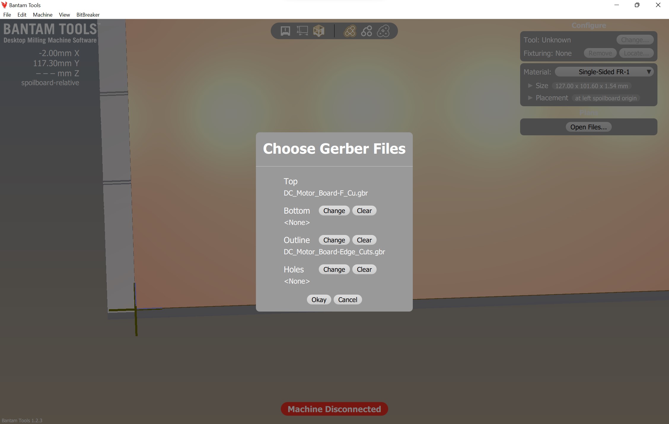
I imported the file into bantam tools. I used my earlier documentation. After clicking the F.Cuts file for the outline I selected the Edge.Cuts. I realized that If I didn’t select this then the mill would only mill a square outline not the one I designed.
I imported the 3 bits I normally used
- PCB engraving bit 0.005”
- 1/64” Flat end mill
- 1/32” Flat end mill
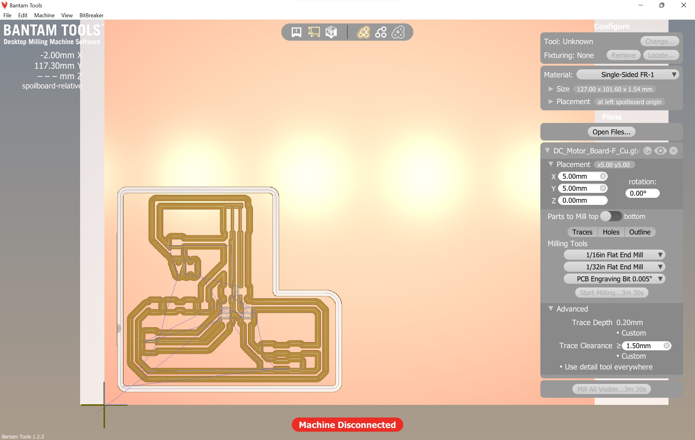
I probed the material thickness, set my origin and rehomed then ran the file. Surprisingly it didn’t need the PCB engraving bit, so the computer prompted me to put the 1/64” Flat end mill in. It was running fine for about 4 seconds then the bit didn’t plunge into the material it was milling out nothing or barley touching the copper. I realized that I didn’t edit the trace depth. The depth was at 0.15mm but it should’ve been 0.20mm. I fixed this the board milled out well
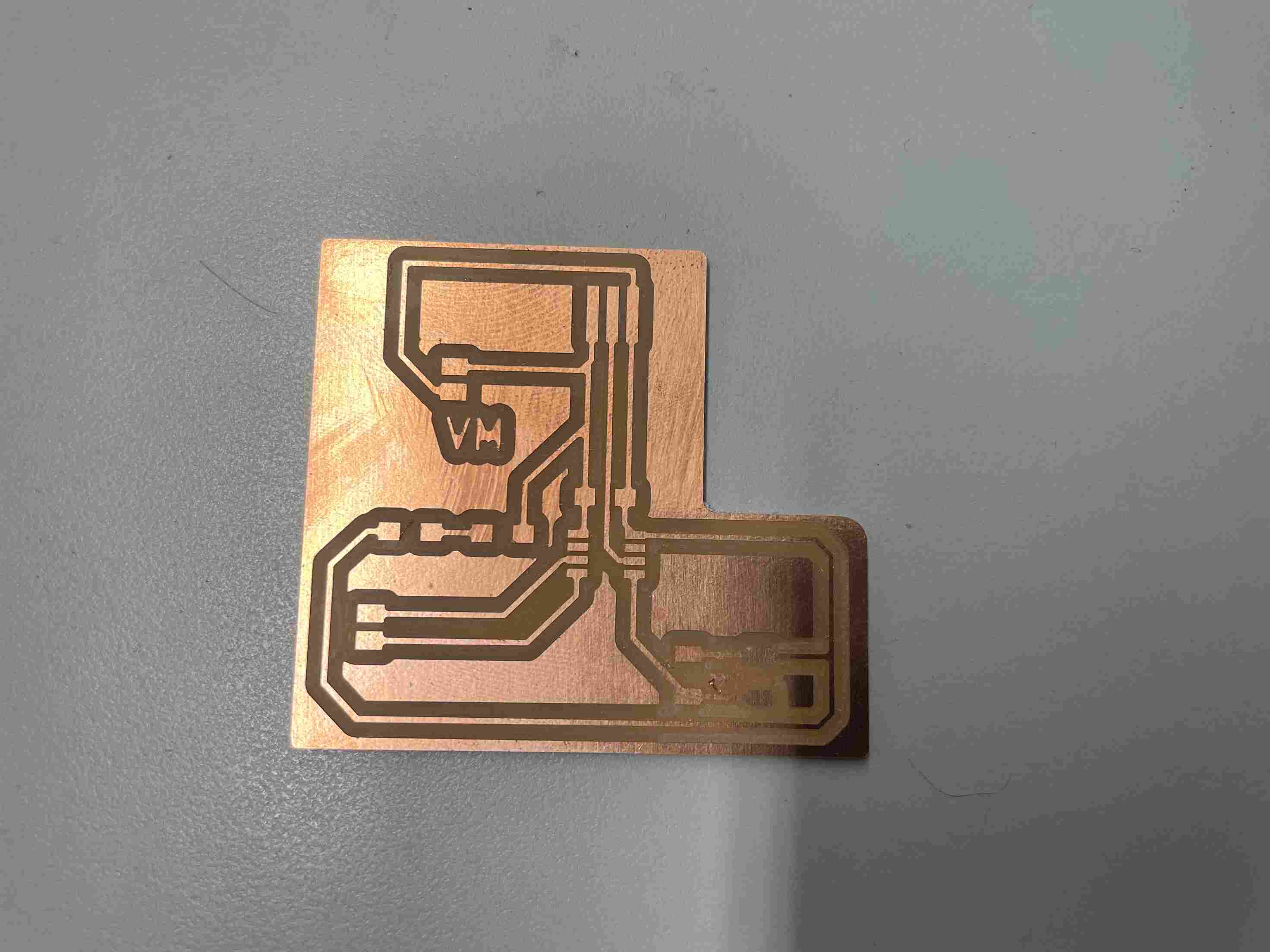
I later decided to add “VM” in the schematic under the headers that would be used to power the motor so I didn’t get confused. I used VM becasue on the other motor drivers VM is used to indicate motor power.
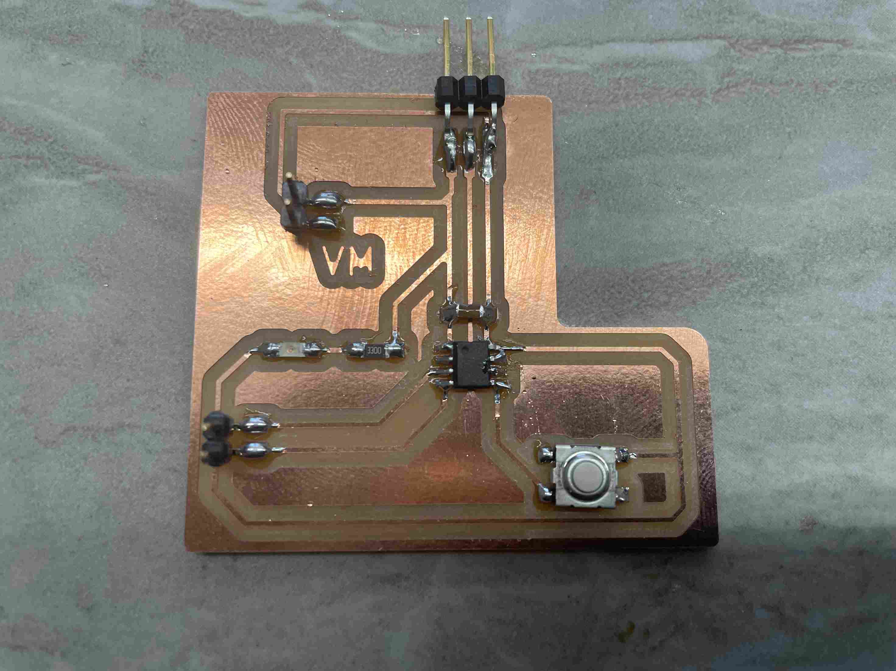
Soldering
I soldered all the components mentioned before my only change is that I decided to have the output pins from the board be vertical headers instead of horizontal headers.
I then soldered pins onto the motor driver using a bread board and multiple vertical headers.
Programming
I was required to test everything, including the programming, with an Arduino before using an ATTiny. I connected all of the necessary wires for the test and I typed this line of code for the Arduino.
#define LED_pin 13

void setup()
{
  pinMode(LED_pin, OUTPUT);
  pinMode(12, OUTPUT);
}

void loop()
{
  analogWrite(13, 80);
  digitalWrite(12, LOW);
}
I ran the code and the motor rotated. I was ready for my board
I opened platform IO and began plugging in everything. From an Arduino (to program the ATTiny412) I connected the power, ground, and UPDI into the 3-pin header. I then connected the two power and ground pins above VM into the motor driver power (making sure the correct pins were connected). Also, from my board I connected the two motor controlling pins into the IN 1, and IN 2. From the two motor A output pins on the driver, I connected them to the DC motor. I just wanted the motor to rotate so I recycled the same code as earlier but changed the pin numbers then plugged the Arduino into my computer. The power LED turned on and I didn’t see any smoke. I uploaded the code and the motor rotated! I also didn’t fry my computer port nor the ATTiny412!
I then wanted to test to see of my motor would rotate if I simply plugged it in. I got a 5V 3A power brick then connected the power and ground pins in place of where I plugged in the Arduino. I didn’t have to plug in the UPDI because the board was already programmed. I proceeded to plug the power brick into an outlet, and it worked, the motor rotated when it received power.
I wanted to test to see if I could use the button. I was used to using it because of embedded programming week and I wrote the code below.
#define PWM_Pin 1
#define Constant_Pin 2
#define Button_Pin 3

void setup()
{
  pinMode(PWM_Pin, OUTPUT);
  pinMode(Constant_Pin, OUTPUT);
  pinMode(Button_Pin, INPUT_PULLUP);
}

void loop()
{
  if ((digitalRead(Button_Pin) == HIGH)) //Button isn't pushed
  {
    digitalWrite(PWM_Pin, 0);// Turns Motor OFF
    digitalWrite(Constant_Pin, LOW);
  }
  else
  {
    analogWrite(PWM_Pin, 80);//Turns motor on OFF
    digitalWrite(Constant_Pin,LOW);
    delay(3000);
  }
I used the Arduino and connected the power, ground, and UPDI again. I uploaded the code and when pressing the button, the DC motor rotated. To test that I could use 1 power source I again powered the board using the power brick mentioned earlier and everything worked. The first video shows me programming while the second one shows the power brick being used.
Problems I Ran Into
- Wanting to use one power source and having to design around that idea by having everything go through my board
- Having to redesign the board multiple times on KiCad
- Looking forever to find a power brick that could use the adapter I needed
- Soldering the pins onto the driver (surprisingly)
- Understanding exactly how voltage worked and being careful not to fry anything
What I Learned
I wanted to use one power source, because that is how I want my final project to function. Due to this idea and the fact that I didn’t have the best motor driver available I had to work around this. Though, I learned a lot because of this, I learned how power works, how a DC motor functions and what a motor driver. I initially thought that power had to come from one wire or else the voltage would decrease. I realized from this week that the power can diverge, and the voltage wouldn’t decrease. I also learned a lot about how a motor driver functions: by taking signals from an Arduino/microcontroller to activate a switch that powers the motor using the separate power source. I though that the DC motor would suck up all the power from everywhere and fry everything. I was also surprised that everything went smoothly post KiCad designing.
Group Assignment
This week’s group assignment was to measure the power consumption of an output device. Pari and myself decided to test my DC motor. I learned how the different voltage levels correlated to different speeds for my motor. The link is here
Files
My PCB files and code files are here