4. Computer Controlled Cutting
Assignment: cut something on the vinylcutt design, lasercut, and document a parametric construction kit, accounting for the lasercutter kerf, which can be assembled in multiple ways
Parametric Design
Researching
Before researching parametric designing, I looked at Alexandra Coston’s sites to get a better understanding of the construction kit. To understand what parametric designing was, I looked this video provided by Mr. Dubick. After watching the video, I loaded up Fusion 360 and started designing my cutouts
Designing and Measuring
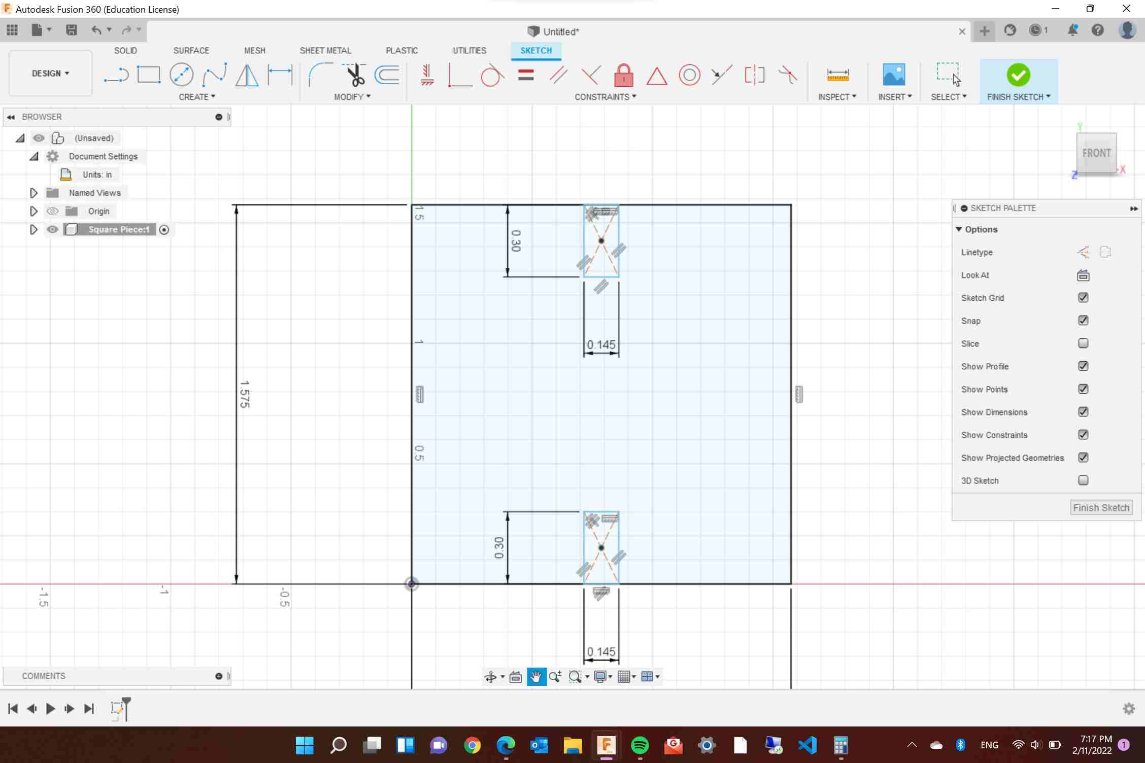
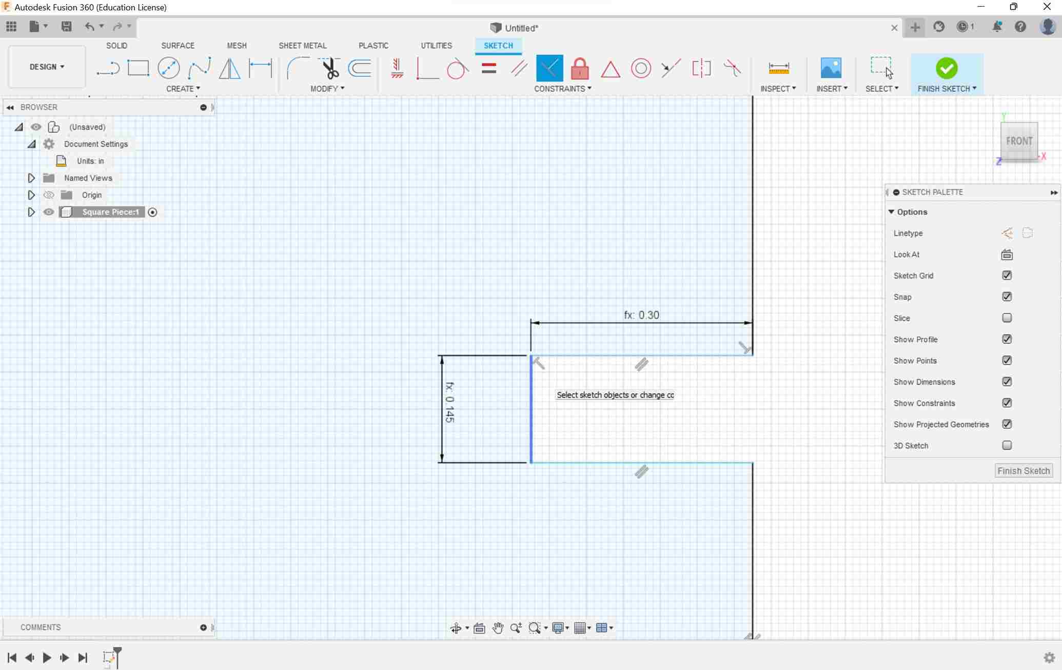
I wanted to create two different pieces, a square and a triangle that I could mix and match. I knew that I needed these parametric to design my construction kit
- material thickness (0.125 in)
- tab length (0.3 in)
- square width and height (4 cm)
- Triangle inscribed circle diameter (1.5 in)
- laser kerf (which came from group assignment) (0.012 in)
When designing in Fusion 360 I used the material thickness as a reference for how big I wanted the pieces to be. A mistake I made was creating parameters first then inputting those values as I made each shape. I would have to press ENTER twice to input the function and I knew that what I was doing was incorrect. I continued making my pieces, but when I finished, I couldn’t edit the size easily. I looked at another Fusion 360 video by Product Design Online on parametric design and understood the problem. I had to create the sketches then create parameters. I then followed these steps in Fusion to create the parametric piece
- I create a square sketch that was 4cm x 4cm
- I create a small tab on the square using construction lines
- Start from the center of one side of the square then create a construction line half of the distance of the material thickness from that point
- Create another point that goes in the opposite direction
- Use a 3-point triangle connecting the two endpoints on the construction line then the tab length I wanted (0.3in )
-
I repeated this same step for each side of the square
-
I used the trim tool to create the tab by deleting the construction lines and lines connecting the tab to the side.
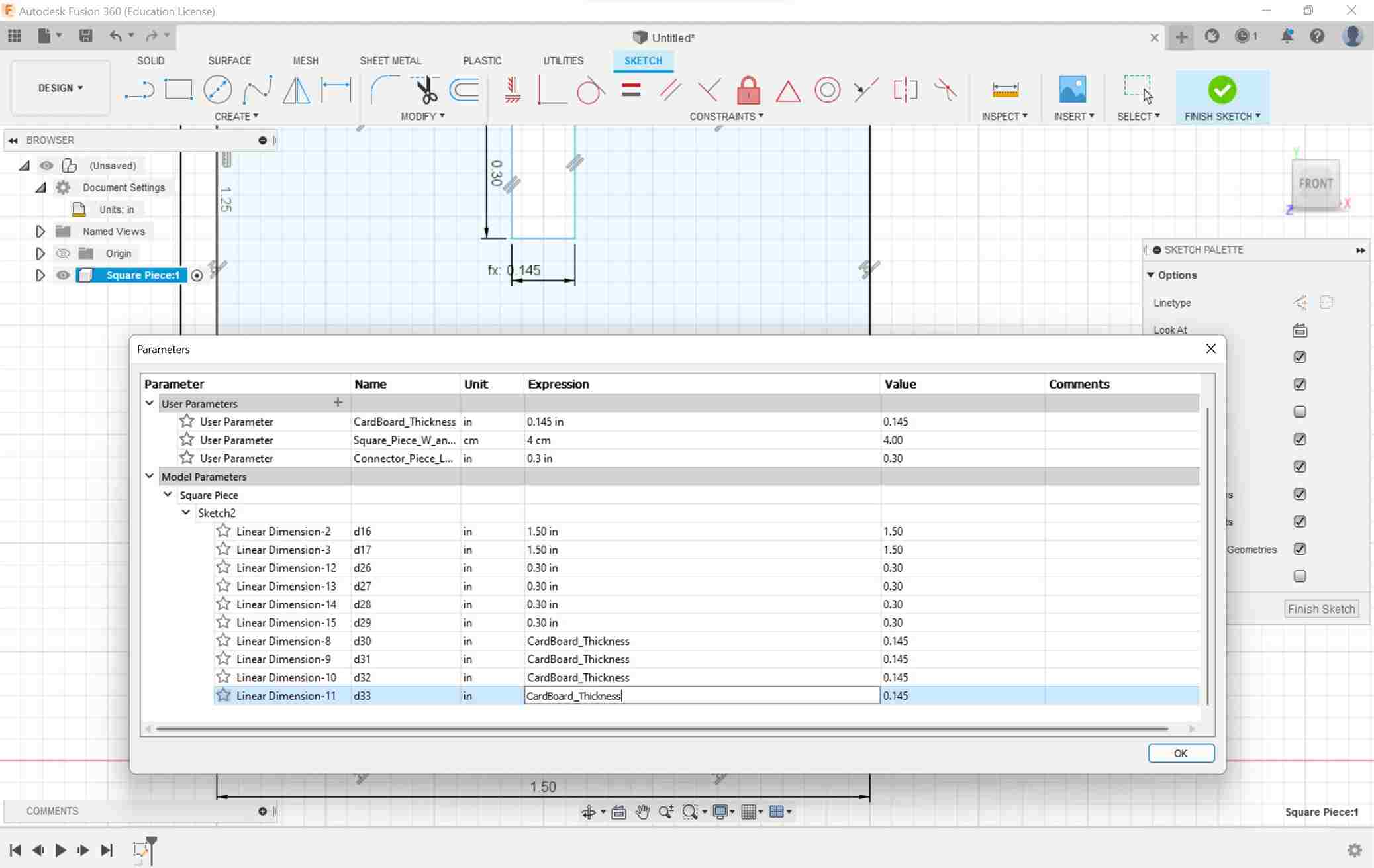
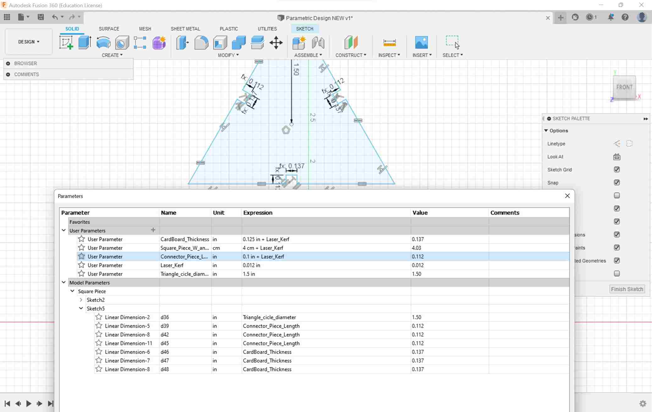
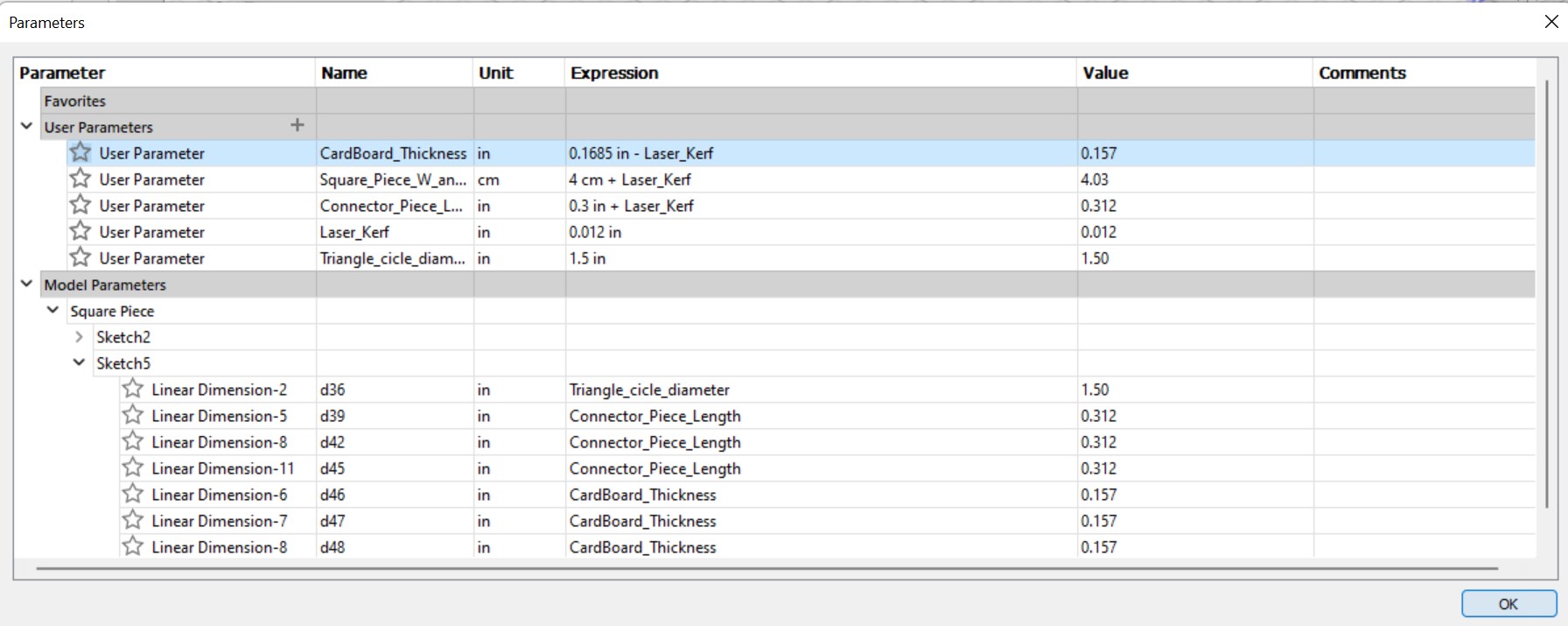
With the piece finished I turned each of the values I measured into parameters then replaced each of the sketch values.
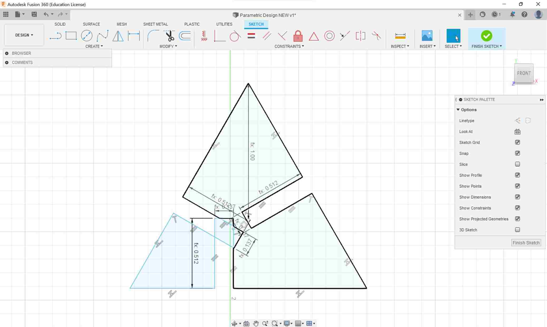
 I repeated the same steps for the triangles.
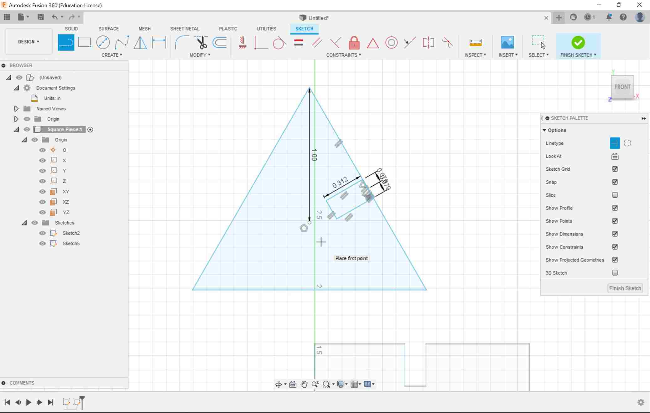
Although, I made another mistake, I didn’t add constraints to each of the tabs so when I edited the parameter values, my triangle was all messed up.
 I fixed this error on both the triangle and square.
However, another factor that I disregarded was the laser kerf. So instead of adding the kerf value into each parameter, I created a kerf parameter then I would add this parameter to the other parameters.
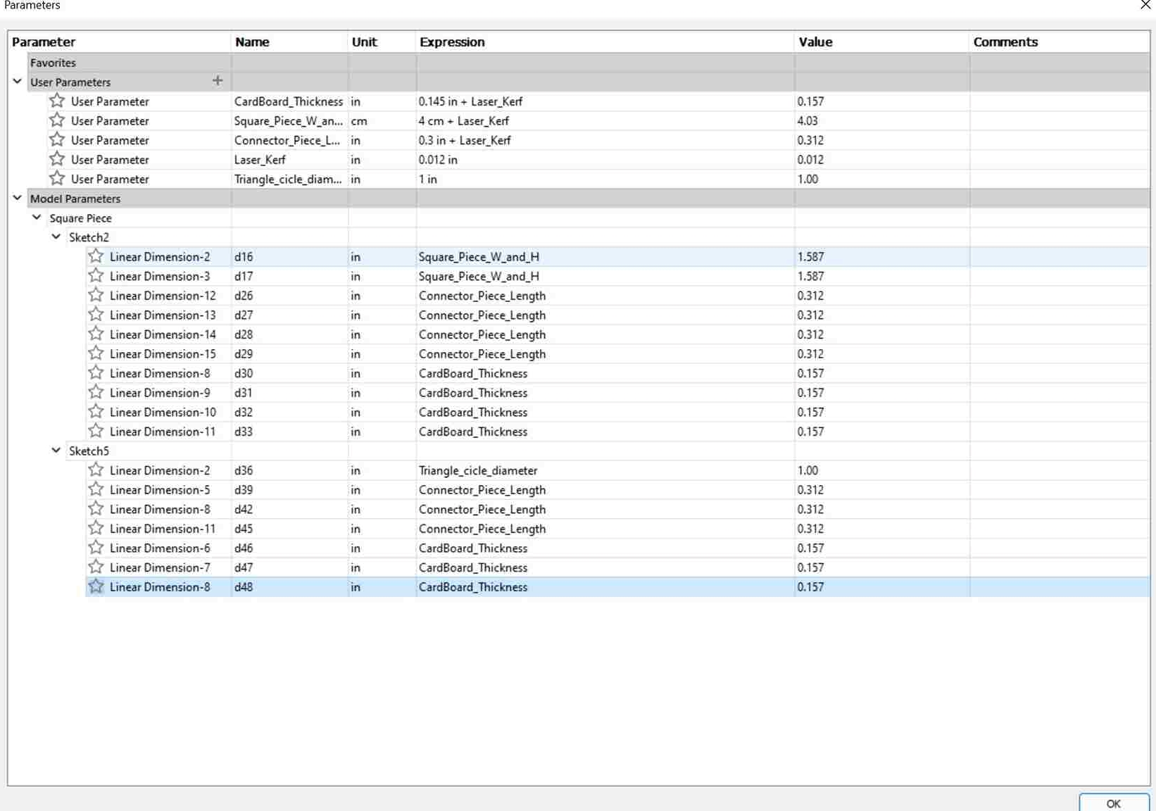 To test to see if my parameters were functioning correctly, I changed the value of the tab length, and the triangle and square adjusted accordingly. My parametric design was complete
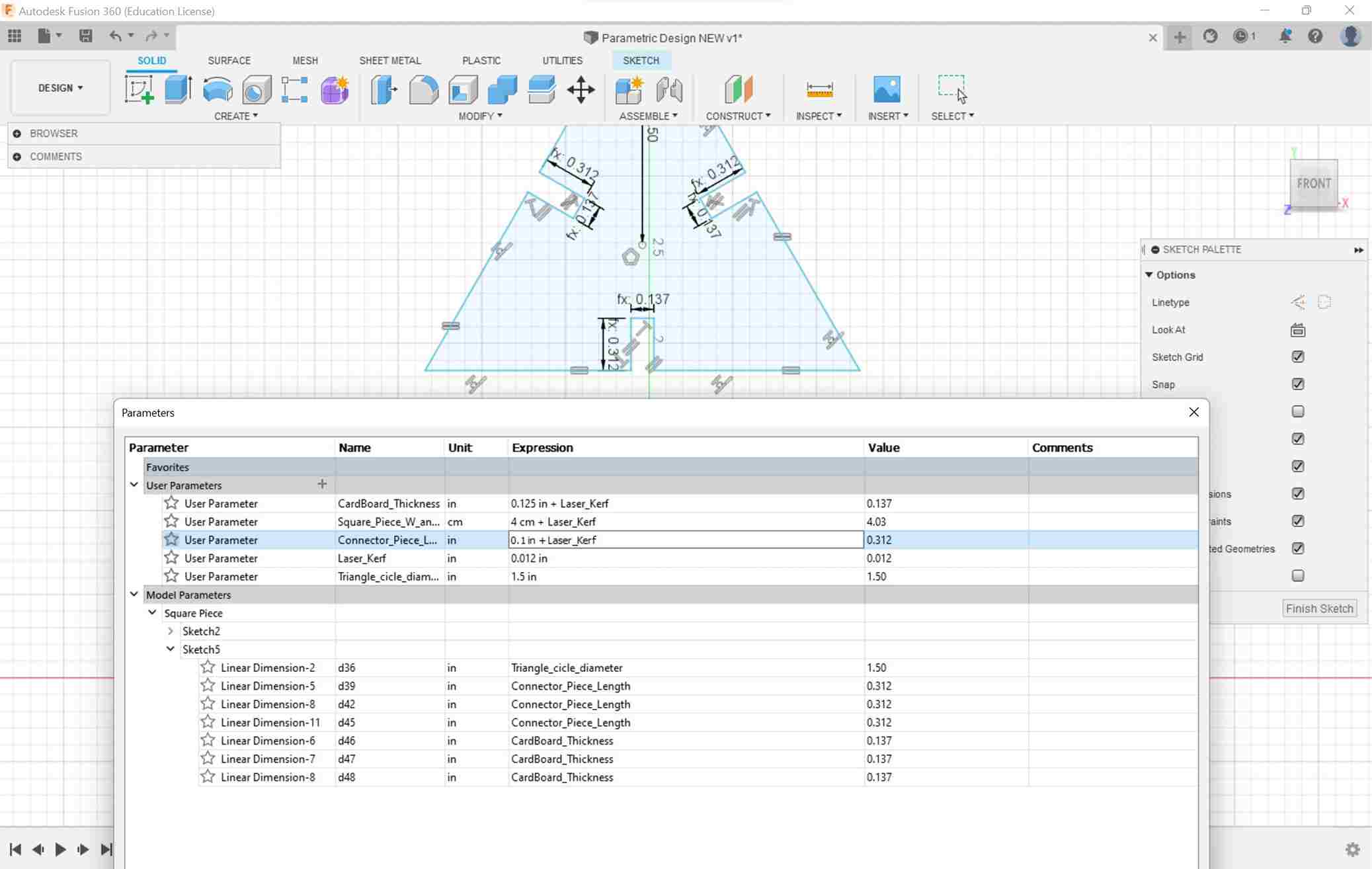
Changing Parameter
Notice the value in the highlighted region. At first it is 0.3 in and the image reflects it, then I change it to 1.0 in and the triangle changes accordingly
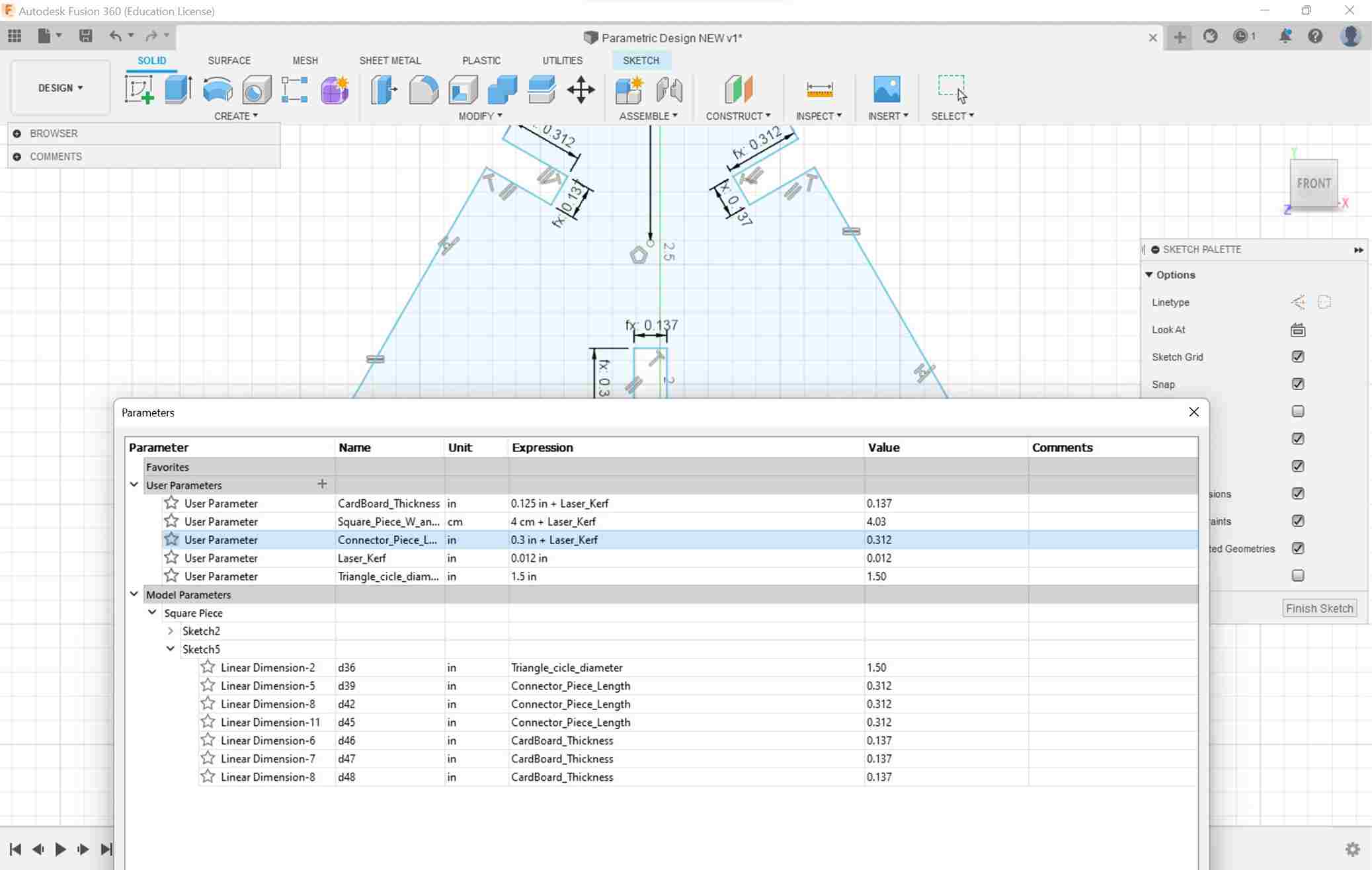
I finished set the parameters for both the triangle and square piece and was ready to print them out.
Uploading and Operating Laser Cutter
I downloaded this file as a . DXF and imported it into Corel Draw but my design was only a line. I realized it was from the plane from Fusion 360. I created my design in the ZX plane, not the YX plane. To fix this error I copied the file and pasted it into another new project on the YX plane then uploaded it.
I imported the settings for cardboard onto the printer which were
Power: 100
Speed: 15
Rate: 25
Made sure this was a vector cut only
I manually focused the laser by lowering the metal piece on the tip of the laser then moving the bed upwards until the bed and metal piece touched. When importing the files into Corel I could either use automatic, English metric or Imperial metric. I used English because most of my parameters were in English; this was a mistake. The files were much bigger than expected and when printing they didn’t mesh correctly.
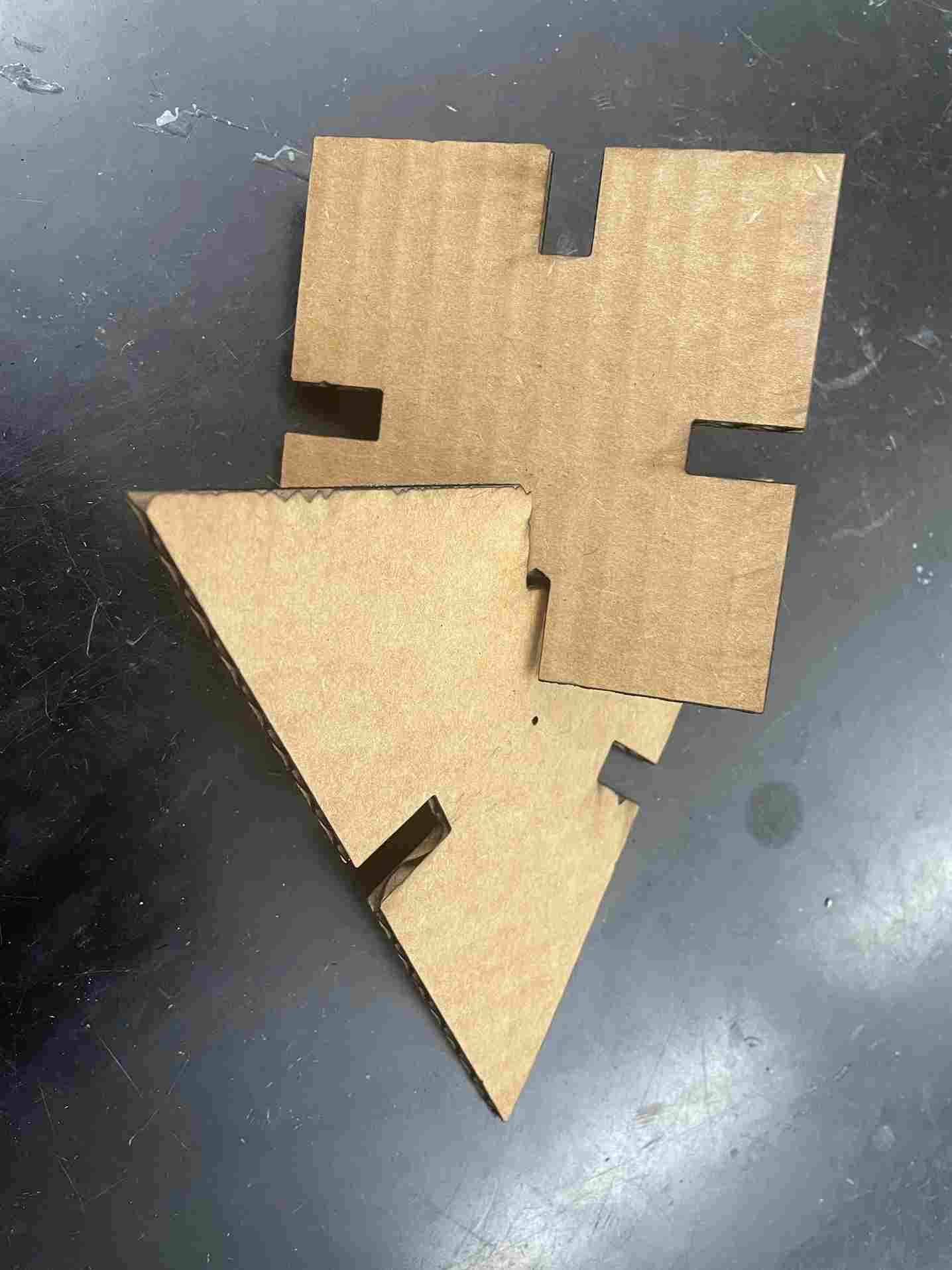
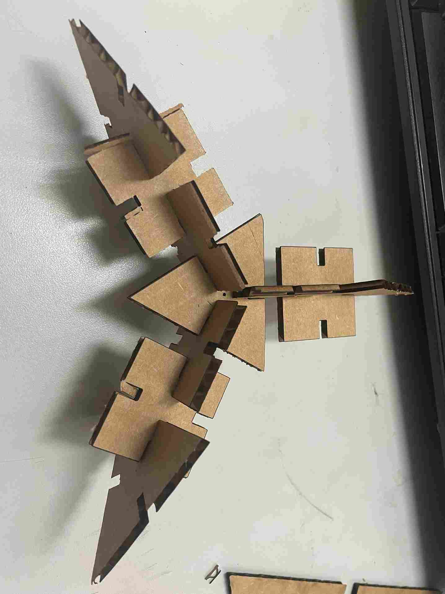
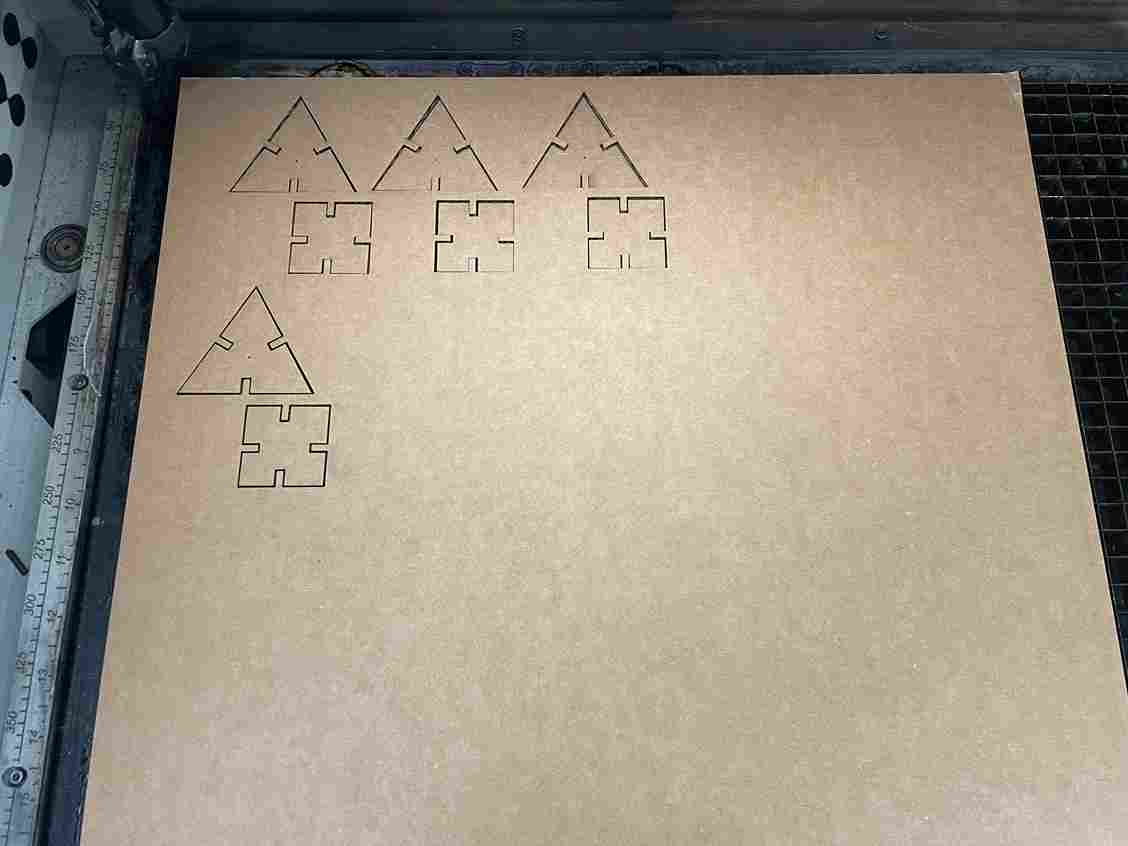
I used automatic and the files looked much smaller and to scale. I printed 5 sets of triangles and squares.
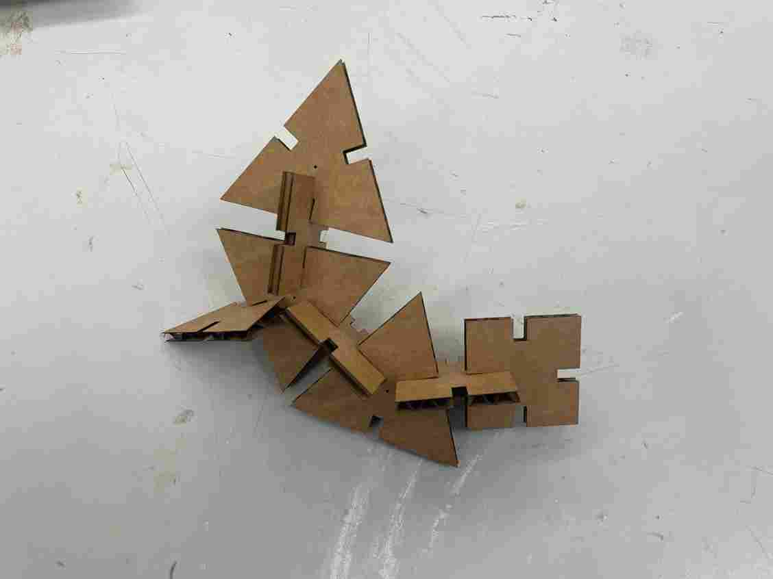
When meshing these cuts, they fit perfectly. Accounting for the kerf was a factor in the connection between each piece.
Revisions
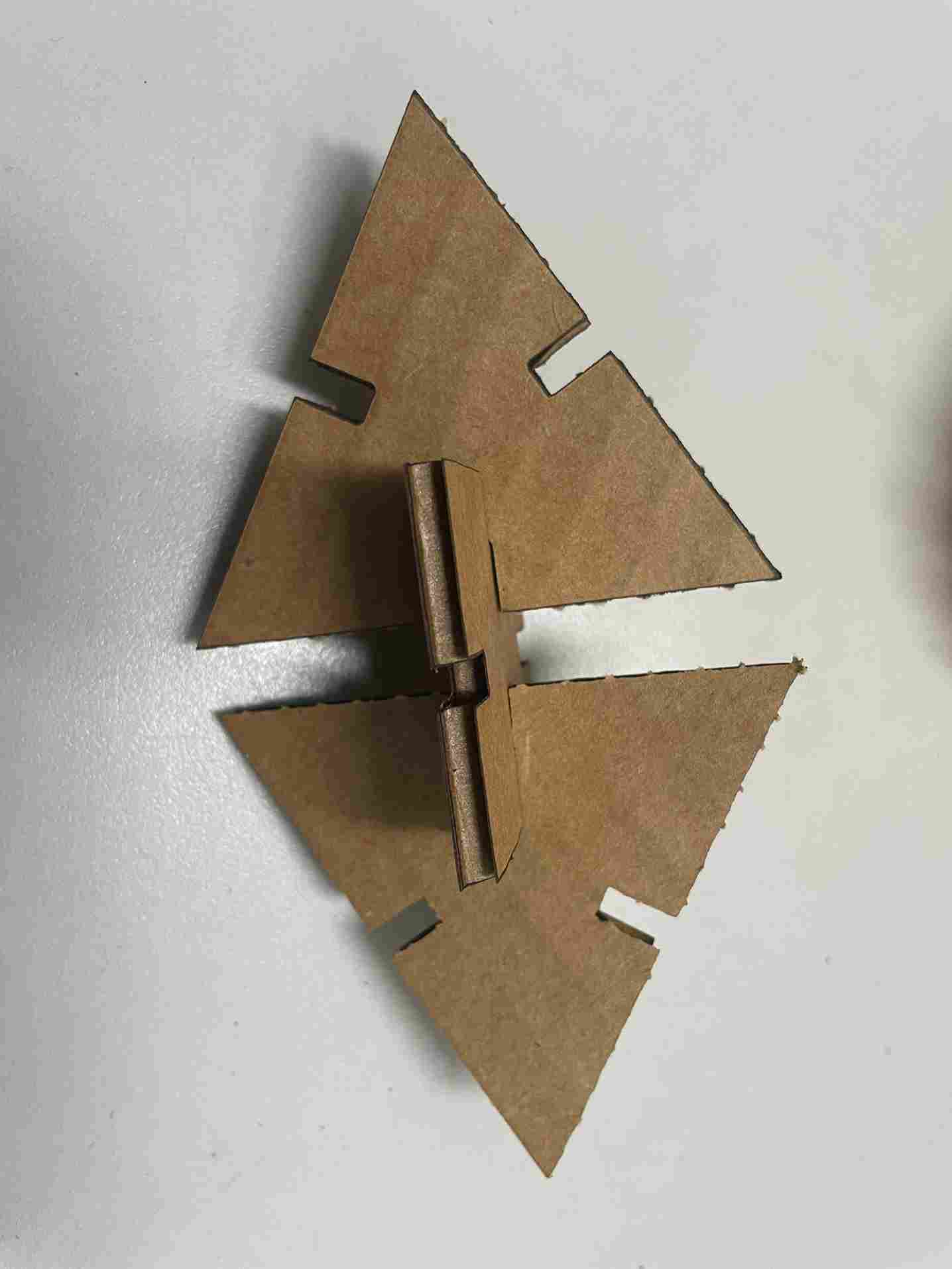
I decided to go back and cut another piece of cardboard. I realized that my first cut wasn’t designed perfectly parametrically and I wanted to do it again. I measured another piece of cardboard, and recived a value of 0.1685 in
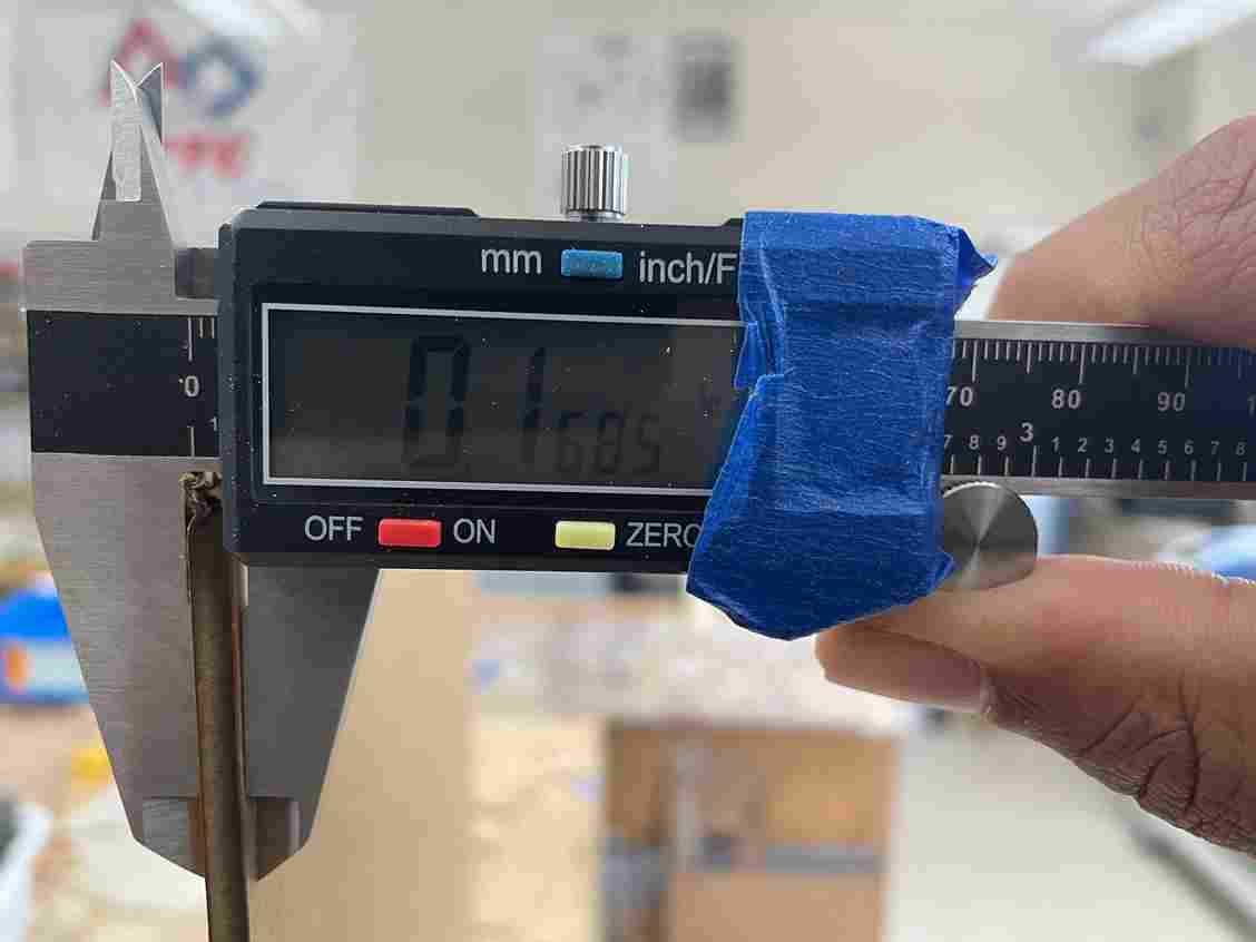
After doing this I went into my parametric design and opened the parameters. I changed the thickness to that value and my mistake earlier was that I added kerf to the tab thickness. I realized that I had to subtract kerf so when the laser cut the tab it would add the kerf back to the tab width making it the exact value I needed at.
I used the same settings mentioned earlier to cut the board. After that I connected them together and they fit even better.
Vinyl Cutting
I’ve had some experience with vinyl cutting before, so I wanted to create a multilayer sticker that was a little more challenging.
Choosing an Image
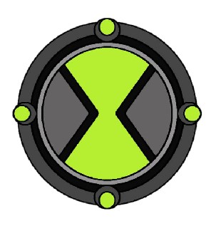
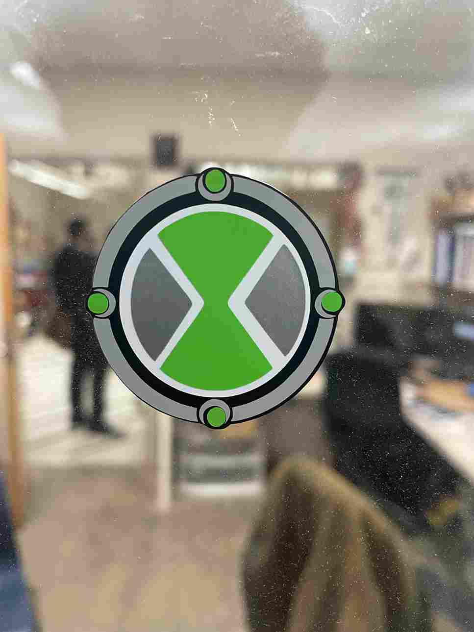
One of my favorite shows as a kid was Ben 10 and he had this device on his wrist called the Omnitrix which could turn him into multiple aliens. I wanted to base my vinyl cut off this.
![]()
Uploading and Creating Bitmap
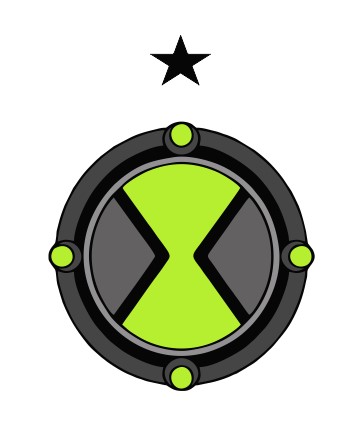
I have never done a multilayer cut before so I found this video by Makers Gonna Learn. A notable tip I gained from the video was create a reference point above your PNG (ie a star) so you can align the sticker correctly I started by doing a quick trace of the PNG then I placed a reference start above the image. I grouped them so I wouldn’t misalign the star when cloning the image.
The sticker had 6 layers, so I copied the image six times. Next, I ungrouped all the images then started deleting the layers that weren’t the same color.
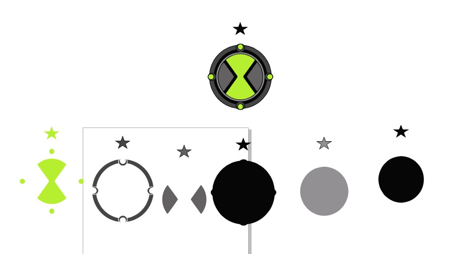
To check that all the pieces were good I placed all the pieces on top of each other with the star being the reference point in Corel Draw. They aligned perfectly
Cutting and Placing
I loaded up the SVG file with all the individual components into Silhouette Studios. Before printing, I got the color I needed then deleted every bitmap except for the one in that color. I loaded up that color on the mat then loaded it and pressed send on the computer. I didn’t need to change material settings; they were already set from a previous class. I repeated this step 6 times with different colors loading and unloading different colors onto the mat.
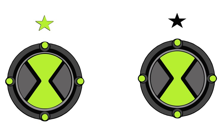
I put each piece on transfer tape and placed them onto the glass the same way I organized each piece in Corel Draw. The star was extremely helpful because I didn’t need to align the piece, just the star above.
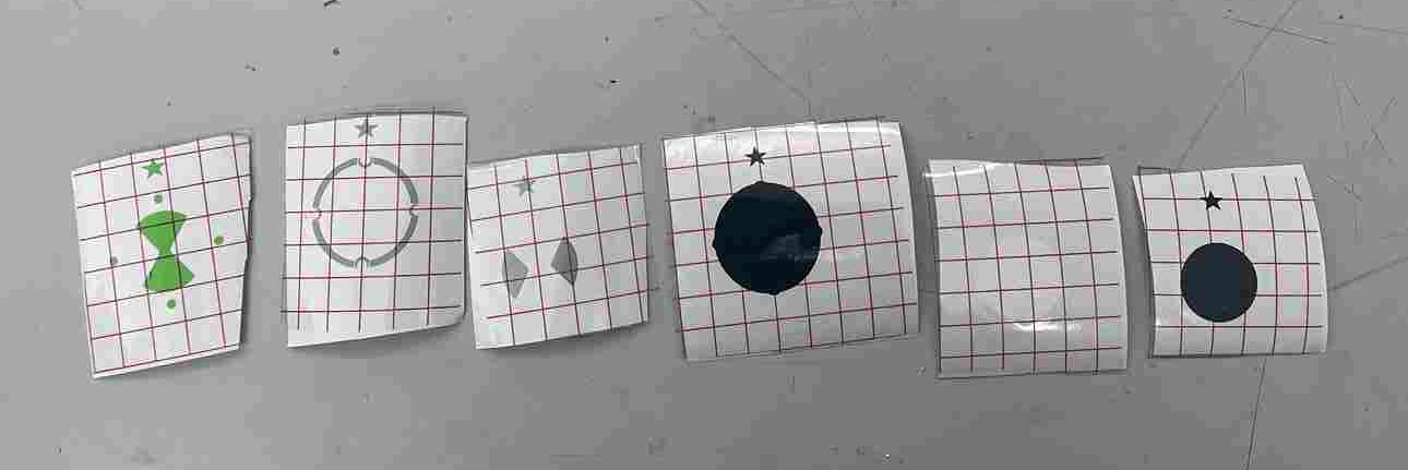
I finished putting all of the pieces together and my vinyl cut was done.
Notable Mistakes
- Setting parameters then creating sketches
- Check the contraints on the sketchs
- Importing files with incorrect scaling
- When importing a file from a 3D software to 2D software make sure the axis are correct
What I Learned
When designing with parameters. I need to first design whatever sketch or 3D model first then set the parameters. With this, the constraints are already set and I won’t need any additional editing. When Importing files from a different location, use automatic scaling when my design is using different units of measure. When using multilayer vinyl cutting uses a reference point so aligning it will be easier. Use transfer tape on each individual piece then place them on to the intended surface starting from the back layer to the front.
Group Assignment
This week my partner Nick Niles worked on characterizing the laser cutter, an Epilog Fusion Pro in our lab. Our documentation is here. Throughout this process I learned that moving the settings such as speed rate and power control how much of the laser is cutting the material. Focus which is the distance the laser is from the material, determines which point of the laser is hitting the surface of the material. Kerf represents the amount cut off from the laser. When cutting or engraving different materials or boards, I will make sure to account for these settings and change them when I want a certain cut to be different.
Files
All of the files are here
Link to image