6. 3D Scanning and printing
This week we worked on testing our 3D printers’ design rulles as a group. We also designed and printed something small on the printers. Finally, using 3D scanning technology, we scanned and printed an item of our choosing.
Assignments for the Week:
Group Assignment:
Test the design rules for your 3D printer(s). You can view our results for our group assignment here
Individual Assignment:
Design and 3D print and object (small, few cm3, limited by printer time) that could not be made subtractively
3D scan an object (and optionally print it)
Designing in Fusion360
For the assignment this week, I really wanted to create a second part for my final project design. During Week 3 and computer-aided design, I worked on creating my mold for Week 10, which is just around the corner! To house the gems I hope to mold, I wanted to make a 3D-printed bracelet or necklace to hold the stone.
Since we were able to find a file and adjust it for something we can use, I found a tutorial on how to create a hinge. When I saw it, one of the designs instantly reminded me of the clasp on a necklace. It doesn’t actually open, and I don’t need it to since the necklace will be long enough to slip over the user’s head. Still, I like the simplicity of the design. So, I took the design and added a few “chain links” to it to start the beginning of my necklace. I kept it to two links so I could quickly print it for this assignment.
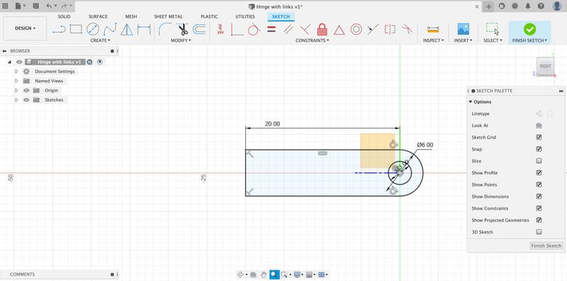
I started the tutorial by creating the first side of where the pin will go. For this section of the hinge, I started with a rectangle sketch and then joined a circle to it to give me the rounded edge.
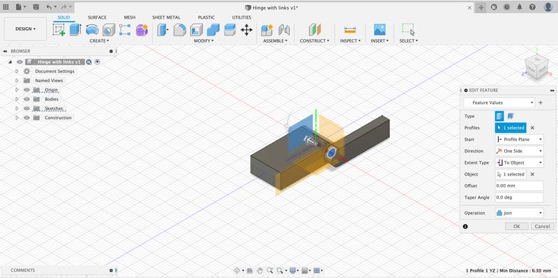
Then, I extruded it and mirrored it so the “clasp” would be the same on both sides. Once the sides were done, I had to create the central pin across that would connect to the two sides.
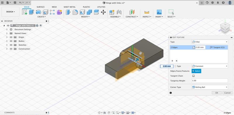
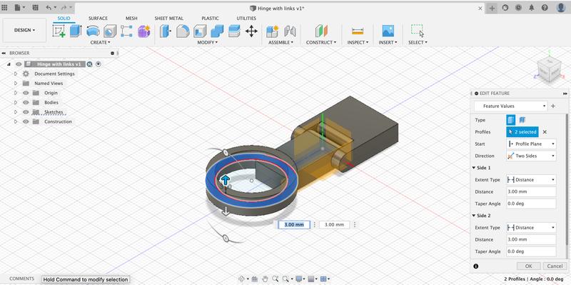
The most difficult part for me to recreate was the fillet where the pin sits next to the edge. Without enough clearance, I wouldn’t have been able to actually rotate the other piece, so it was important to make this step work. I had to redo this several times before it actually took. I am not sure if it was an issue with Fusion360, but after several tries, I closed out the software and reopened my file. On this try, it finally worked.
I completed the hinge piece and then proceeded to add my links for the bracelet. I started by drawing to circles, one inside another.
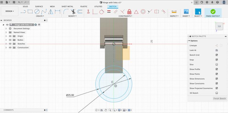
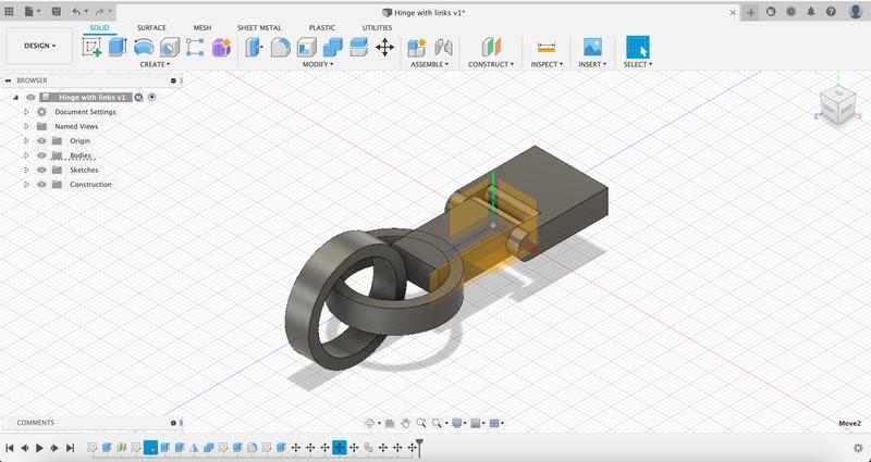
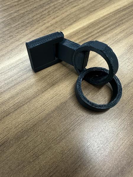
Once I had the ring outline shape, I then extruded it to create a solid ring shape. I moved this ring shape to merge with the edge of the clasp and combined the two pieces together. You can see where the ring shows through the side of the clasp in the final image of the 3D printed piece.
I then duplicatd the ring link, flipped it and joined it with the previous link. For this part of the week, I stopped the design here so I could quickly print it, but for my final project, I plan on adding more links to complete the bracelet design.
3D Printing
After I finished the design file in Fusion360, it was time to prepare it for printing. I exported the STL version of my file from Fusion360. I read about this file type here and learned a bit more about stl files. This reading was useful in the latter part of this week’s assignments, when we had to 3D scan something.
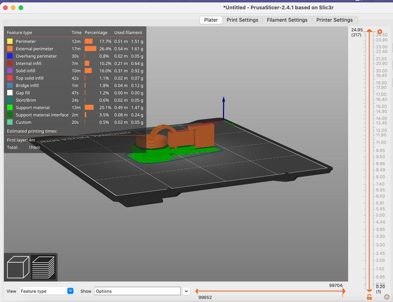
I then imported the file into Prusa Slicer, since the Prusa printers are what we use in the lab.
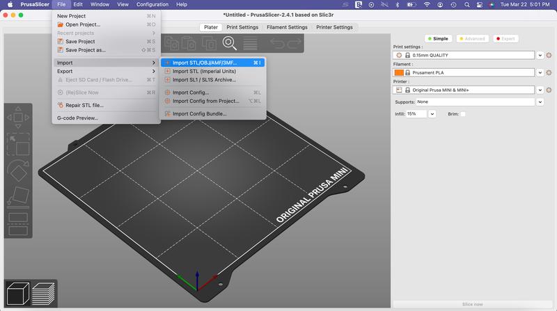
After importing my file, the process is pretty simple. We have used the printers many times in our lab, but funny enough, I always forget this step of converting the STL file to gcode so the printer knows what to do. That is the step in Prusa Slicer. It “slices” the STL file into layers for the machine to read. These layers are what the filament lays down through each level.
Once my file is imported, I rotate the board around to make sure it is sitting flat on the bed surface. Since this design does not sit flat because of the links, I added supports to the design. Adding supports is quick and easy tool in the slicer. For my specific design, I only added supports on the buildplate instead of all over the design. This added supports below the links so they would form correctly.
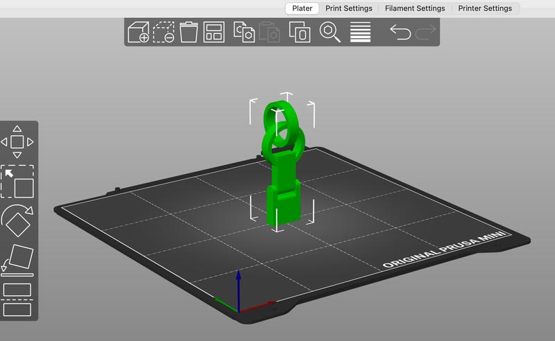
I made sure the output detail was set to 0.20 SPEED instead of an ultra fine detail so the print would not take long at all.
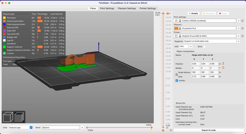
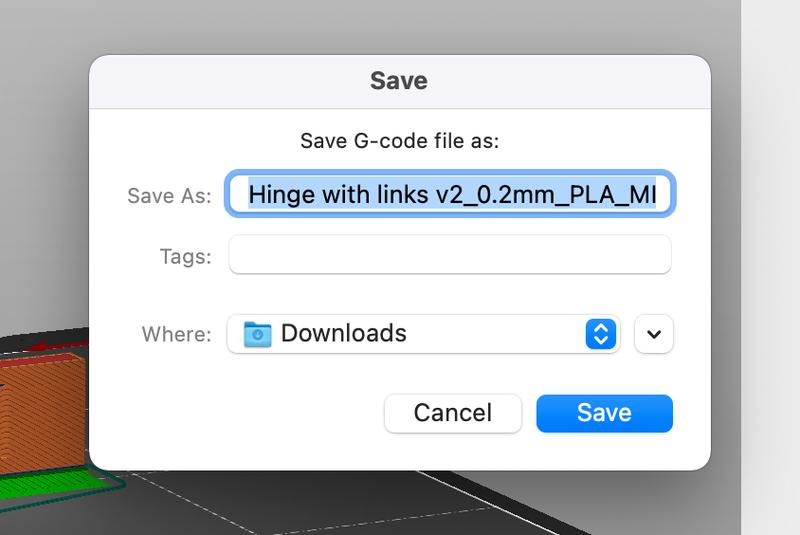
After that I was ready to export the g-code file.
The g-code file is then brought into our Octoprint setup for our 3D print farm. We are lucky that we have enough printers for a class setting. I opened our direct link for the printer I was going to use. I cleaned the bed with alcohol as a first step. I then loaded the file and hit the print button. The software does the rest. The bed and nozzle began to heat up. Once they are ready, the printer lays down a calibration line on the edge of the bed to extrude filament from the nozzle.
Then the print begins. I had set up my phone to do a timelapse of the print, but at some point early on, it was knocked over and only recorded the back wall. I will try to print it again to get a good video of it!
We have a process in the lab that if a printer is needed and you need to print on it, then you can remove the print from the bed and place it in the pick up box. Someone needed to use the printer and so I picked up my finished print from the box.
3D Scanning
Surprisingly, this part of the assignment was a little harder than I thought it would be! I tried several different apps without much success! Finally, I was able to get a working model on Polycam, but had a lot of trouble getting the file from my phone.
This was my first working attempt at scanning. It was a decent scan, but you can see from the original image on the left there is a lot of detail missing and parts of the scan are grainy.
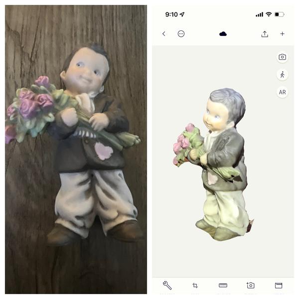
Overall, I was still happy with how it turned out.
Since I couldn’t get my file, I made another attempt using a different app. Colleague Scott Moulton had done some extensive research on this assignment, and he suggested I try KIRI Engine. So, let’s just say 3D scanning and I do not go together well. No matter what I tried I couldn’t get it to work. See some disastrous attempts below. I did some research to see what I might doing wrong - obviously this was a case of user error!
I adjusted lighting, made sure I didn’t have any shiny or reflective products, took slow steady pictures from every angle. Still a mess.
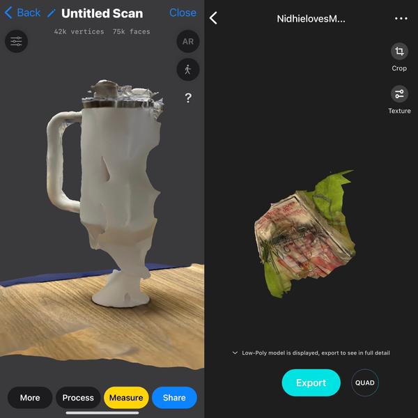
Scott sat with me and helped me rotate another object while he slowly turned the board it was sititng on. Finally, he suggested I try saving the file as an OBJ file instead of STL. Would love to find out why one was better than another, but it finally worked!
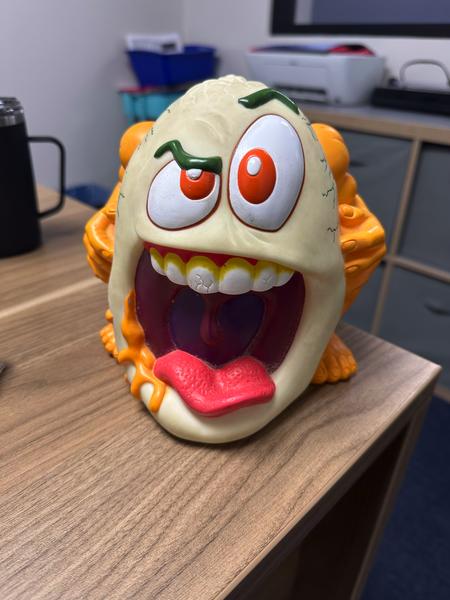
Here is the actual item I scanned:
Advantages and Disadvantages
As with most design concepts, 3D printing also comes with it’s own set of advantages and disadvantes.
One of the easiest to see, is the limitation of wasted material if design files are done correctly. The only material used in this additive manufacturing process is the filament used for printing. This essentially eliminates the same wasted material we find in subtractive manufacturing.
On the flip side, one of the first things I noticed when printing was the balance between quality and speed. Although we can produce some items very quickly at a lower quality setting, we lose the fine details. If we need a print at higher quality or with more details, then the downside is the print can take much, much longer.
Click the link for the file below to download all of the files I used in this week’s assignments. Files