11. Output Devices
Assignments for the Week:
Group Assignment:
Measure the power consumption of an output device.
For the group assignment this week, Barbara Morrow and I pulled out our lab’s DC power supply to test the power consumption of a motor. We used alligator clips to attach to the positive and negative leads of the motor. To begin, we started off by agreeing to use small increments of adjusting the voltage and reading the current and power, which is automatically adjusted. You can view the details of our group assignment here.
Individual Assignment:
Add an output device to a microcontroller board you’ve designed and program it to do something
Prep
I have gone back and forth several times on what I want the lights on the dress to look like. At times, I have felt like I have “squirrel” syndrome while looking through the hundreds of ideas online. Neil’s output lecture this week also had me wondering what I could do with Charlieplexing after I actually figure out how it works. Using his method in the lecture, I was able to draw a quick 4x4 grid but the whole layering concept is yet to be understood!
In order to understand my outputs for this week, I began setting up a string of neopixels in Tinkercad. Using the Arduino, I made sure I understood how to program them and turn them on. This video provided some great info on how to add an external power source because the Arduino can’t handle lighting more than 8 neopixels. More on that below! This is the video of my Tinkercad mockup.
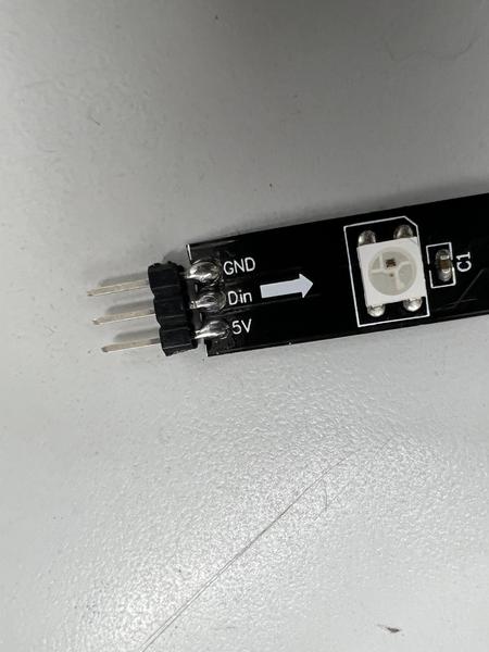
After I made sure my code worked, I set out to light up 8 neopixels with an actual Arduino. I soldered 3 header pins to the end of my neopixel strip to make plugging them into the boards easier.
On the computer I was using, I did not have the Adafruit Neopixel library installed, so I did that first. To do so, go to Tools –> Manage Libraries. Search for the Adafruit Neopixel library and then hit the install button. It took just a few seconds and then I was ready to go.
I copied the code from Tinkercad and pasted it into my Arduino IDE. To make sure it was all correct, I compiled it and set it aside. The next step was to set up the neopixel strip with the Arduino. I attached wires to my header pins and plugged them into the GND, 5V and pin 2 slots on the Arduino. I set the number of pins in the code to 8 just to do this quick test. I then plugged it into the computer and uploaded the program. It worked as expected.
Since I just used my Arduino Uno to program the strip, the first thing I needed to do was turn it back into a UPDI programmer. I ran the jtag code from a few weeks prior back onto the board and waited for the two quick flashing lights to confirm it worked. Next, I needed to set up my neopixel stip with my ATtiny412.
I opted to use a breadboard to figure out how to set this part up. I know Neil says he really doesn’t like them because it’s so quick to mill a board, but I haven’t yet mastered the art of designing a board quick enough to make that happen. I’m sure by the end of Fab Academy that will be a different story!
So, I soldered an ATtiny412 chip to an 8-pin breakout board and added headers to both sides. This gave me the ability to plug it into a breadboard and figure out my wiring. I used the pinout for the chip to find my GND and VCC and wire those up to the Uno. Next, I selected the pin on the chip I plan on using (pin 2) and also found the UPDI pin (pin 6). Armed with this info, I plugged the Arduino into the correct parts on the breadboard. I then plugged in my neopixel and uploaded my code…and nothing happened!
I kept getting a result saying board not found. I made sure in my IDE, I had selected the 412 as my target board and the Uno as my programmer. I checked and rechecked the pinout. Everything was correct. It should have worked. I started researching the internet for any ideas or issue discussions I could find. I couldn’t find the exact issue anywhere. I must have been on the search for about 2 hours going down that wonderful internet rabbit-hole. One of our instructors, Tom Dubick, saw my frustration and threw me a lifeline. He told me to stop and think about what I was programming. I said neopixels. He said, no, think again. WHAT are you programming? It clicked! The code I copied and pasted was using the Arduino Uno and I needed to get code for the 412!
So, I began searching for “tiny neopixel programming” or anything similar. I found lots of info and just had to weed through it. I finally came across this site and it had the files I needed. I felt like an idiot though, as this was the exact link Neil posted in his notes for this week! I was happy even though I had spent so much time searching. A few months ago, I never would have even known what to search for. And now, albeit it might take me a while, I can figure out at least my starting direction!
Here is the code for the neopixels
#include <tinyNeoPixel.h>

#define PIN PIN_PA1

// Parameter 1 = number of pixels in strip
// Parameter 2 = Arduino pin number (most are valid)
// Parameter 3 = pixel type
//   NEO_GRB     Pixels are wired for GRB bitstream (most NeoPixel products)
//   NEO_RGB     Pixels are wired for RGB bitstream (v1 FLORA pixels, not v2)
//   NEO_RGBW    Pixels are wired for RGBW bitstream (NeoPixel RGBW products)
tinyNeoPixel strip = tinyNeoPixel(60, PIN, NEO_GRB + NEO_KHZ800);

// IMPORTANT: To reduce NeoPixel burnout risk, add 1000 uF capacitor across
// pixel power leads, add 300 - 500 Ohm resistor on first pixel's data input
// and minimize distance between Arduino and first pixel.  Avoid connecting
// on a live circuit...if you must, connect GND first.

void setup() {
  strip.begin();
  strip.show(); // Initialize all pixels to 'off'
}

void loop() {
  // Some example procedures showing how to display to the pixels:
  colorWipe(strip.Color(255, 0, 0), 50); // Red
  colorWipe(strip.Color(0, 255, 0), 50); // Green
  colorWipe(strip.Color(0, 0, 255), 50); // Blue
  // colorWipe(strip.Color(0, 0, 0, 255), 50); // White RGBW
  // Send a theater pixel chase in...
  theaterChase(strip.Color(127, 127, 127), 50); // White
  theaterChase(strip.Color(127, 0, 0), 50); // Red
  theaterChase(strip.Color(0, 0, 127), 50); // Blue

  rainbow(20);
  rainbowCycle(20);
  theaterChaseRainbow(50);
}

// Fill the dots one after the other with a color
void colorWipe(uint32_t c, uint8_t wait) {
  for (uint16_t i = 0; i < strip.numPixels(); i++) {
    strip.setPixelColor(i, c);
    strip.show();
    delay(wait);
  }
}

void rainbow(uint8_t wait) {
  uint16_t i, j;

  for (j = 0; j < 256; j++) {
    for (i = 0; i < strip.numPixels(); i++) {
      strip.setPixelColor(i, Wheel((i + j) & 255));
    }
    strip.show();
    delay(wait);
  }
}

// Slightly different, this makes the rainbow equally distributed throughout
void rainbowCycle(uint8_t wait) {
  uint16_t i, j;

  for (j = 0; j < 256 * 5; j++) { // 5 cycles of all colors on wheel
    for (i = 0; i < strip.numPixels(); i++) {
      strip.setPixelColor(i, Wheel(((i * 256 / strip.numPixels()) + j) & 255));
    }
    strip.show();
    delay(wait);
  }
}

// Theatre-style crawling lights.
void theaterChase(uint32_t c, uint8_t wait) {
  for (int j = 0; j < 10; j++) { // do 10 cycles of chasing
    for (int q = 0; q < 3; q++) {
      for (uint16_t i = 0; i < strip.numPixels(); i = i + 3) {
        strip.setPixelColor(i + q, c);  // turn every third pixel on
      }
      strip.show();

      delay(wait);

      for (uint16_t i = 0; i < strip.numPixels(); i = i + 3) {
        strip.setPixelColor(i + q, 0);      // turn every third pixel off
      }
    }
  }
}

// Theatre-style crawling lights with rainbow effect
void theaterChaseRainbow(uint8_t wait) {
  for (int j = 0; j < 256; j++) {   // cycle all 256 colors in the wheel
    for (int q = 0; q < 3; q++) {
      for (uint16_t i = 0; i < strip.numPixels(); i = i + 3) {
        strip.setPixelColor(i + q, Wheel((i + j) % 255)); // turn every third pixel on
      }
      strip.show();

      delay(wait);

      for (uint16_t i = 0; i < strip.numPixels(); i = i + 3) {
        strip.setPixelColor(i + q, 0);      // turn every third pixel off
      }
    }
  }
}

// Input a value 0 to 255 to get a color value.
// The colours are a transition r - g - b - back to r.
uint32_t Wheel(byte WheelPos) {
  WheelPos = 255 - WheelPos;
  if (WheelPos < 85) {
    return strip.Color(255 - WheelPos * 3, 0, WheelPos * 3);
  }
  if (WheelPos < 170) {
    WheelPos -= 85;
    return strip.Color(0, WheelPos * 3, 255 - WheelPos * 3);
  }
  WheelPos -= 170;
  return strip.Color(WheelPos * 3, 255 - WheelPos * 3, 0);
}
AND you will also need this .h file that the above code calls for. This code file is included as another tab in the program. Do not insert it into the same tab as the code above.
/*--------------------------------------------------------------------
  This file is part of the tinyNeoPixel library, derived from
  Adafruit_NeoPixel.

  NeoPixel is free software: you can redistribute it and/or modify
  it under the terms of the GNU Lesser General Public License as
  published by the Free Software Foundation, either version 3 of
  the License, or (at your option) any later version.

  NeoPixel is distributed in the hope that it will be useful,
  but WITHOUT ANY WARRANTY; without even the implied warranty of
  MERCHANTABILITY or FITNESS FOR A PARTICULAR PURPOSE.  See the
  GNU Lesser General Public License for more details.

  You should have received a copy of the GNU Lesser General Public
  License along with NeoPixel.  If not, see
  <http://www.gnu.org/licenses/>.
  --------------------------------------------------------------------*/
// *INDENT-OFF* astyle hates this file
// *PAD-OFF* and destroys the lookup tables!
#ifndef TINYNEOPIXEL_H
#define TINYNEOPIXEL_H

#include <Arduino.h>

#if (__AVR_ARCH__ < 100)
  #error "This version of the library only supports AVRxt parts (tinyAVR 0/1/2-series, megaAVR 0-series and the AVR DA/DB/DD/EA parts. For tinyNeoPixel for classic AVR, get from ATTinyCore package"
#endif

// The order of primary colors in the NeoPixel data stream can vary
// among device types, manufacturers and even different revisions of
// the same item.  The third parameter to the Adafruit_NeoPixel
// constructor encodes the per-pixel byte offsets of the red, green
// and blue primaries (plus white, if present) in the data stream --
// the following #defines provide an easier-to-use named version for
// each permutation.  e.g. NEO_GRB indicates a NeoPixel-compatible
// device expecting three bytes per pixel, with the first byte
// containing the green value, second containing red and third
// containing blue.  The in-memory representation of a chain of
// NeoPixels is the same as the data-stream order; no re-ordering of
// bytes is required when issuing data to the chain.

// Bits 5,4 of this value are the offset (0-3) from the first byte of
// a pixel to the location of the red color byte.  Bits 3,2 are the
// green offset and 1,0 are the blue offset.  If it is an RGBW-type
// device (supporting a white primary in addition to R,G,B), bits 7,6
// are the offset to the white byte...otherwise, bits 7,6 are set to
// the same value as 5,4 (red) to indicate an RGB (not RGBW) device.
// i.e. binary representation:
// 0bWWRRGGBB for RGBW devices
// 0bRRRRGGBB for RGB

// RGB NeoPixel permutations:
// Offset:         W          R          G          B
#define NEO_RGB  ((0 << 6) | (0 << 4) | (1 << 2) | (2))
#define NEO_RBG  ((0 << 6) | (0 << 4) | (2 << 2) | (1))
#define NEO_GRB  ((1 << 6) | (1 << 4) | (0 << 2) | (2)) // GRB is very common
#define NEO_GBR  ((2 << 6) | (2 << 4) | (0 << 2) | (1))
#define NEO_BRG  ((1 << 6) | (1 << 4) | (2 << 2) | (0))
#define NEO_BGR  ((2 << 6) | (2 << 4) | (1 << 2) | (0))

// RGBW NeoPixel permutations; all 4 offsets are distinct
// Offset:         W          R          G          B
#define NEO_WRGB ((0 << 6) | (1 << 4) | (2 << 2) | (3))
#define NEO_WRBG ((0 << 6) | (1 << 4) | (3 << 2) | (2))
#define NEO_WGRB ((0 << 6) | (2 << 4) | (1 << 2) | (3))
#define NEO_WGBR ((0 << 6) | (3 << 4) | (1 << 2) | (2))
#define NEO_WBRG ((0 << 6) | (2 << 4) | (3 << 2) | (1))
#define NEO_WBGR ((0 << 6) | (3 << 4) | (2 << 2) | (1))

#define NEO_RWGB ((1 << 6) | (0 << 4) | (2 << 2) | (3))
#define NEO_RWBG ((1 << 6) | (0 << 4) | (3 << 2) | (2))
#define NEO_RGWB ((2 << 6) | (0 << 4) | (1 << 2) | (3))
#define NEO_RGBW ((3 << 6) | (0 << 4) | (1 << 2) | (2))
#define NEO_RBWG ((2 << 6) | (0 << 4) | (3 << 2) | (1))
#define NEO_RBGW ((3 << 6) | (0 << 4) | (2 << 2) | (1))

#define NEO_GWRB ((1 << 6) | (2 << 4) | (0 << 2) | (3))
#define NEO_GWBR ((1 << 6) | (3 << 4) | (0 << 2) | (2))
#define NEO_GRWB ((2 << 6) | (1 << 4) | (0 << 2) | (3))
#define NEO_GRBW ((3 << 6) | (1 << 4) | (0 << 2) | (2))
#define NEO_GBWR ((2 << 6) | (3 << 4) | (0 << 2) | (1))
#define NEO_GBRW ((3 << 6) | (2 << 4) | (0 << 2) | (1))

#define NEO_BWRG ((1 << 6) | (2 << 4) | (3 << 2) | (0))
#define NEO_BWGR ((1 << 6) | (3 << 4) | (2 << 2) | (0))
#define NEO_BRWG ((2 << 6) | (1 << 4) | (3 << 2) | (0))
#define NEO_BRGW ((3 << 6) | (1 << 4) | (2 << 2) | (0))
#define NEO_BGWR ((2 << 6) | (3 << 4) | (1 << 2) | (0))
#define NEO_BGRW ((3 << 6) | (2 << 4) | (1 << 2) | (0))

#define NEO_KHZ800 0x0000 ///< 800 KHz data transmission

// 400 kHz neopixels are virtually absent from the market today
// They are not supported.

// These two tables are declared outside the Adafruit_NeoPixel class
// because some boards may require oldschool compilers that don't
// handle the C++11 constexpr keyword.

/* A pre-calculated 8-bit sine look-up table stored in flash for use
with the sine8() function. This is apparently of use in some animation
algorithms. If __AVR_ARCH__==103, then all of the flash is memory
mapped, and we can simply declare it const, access it like a
normal variable, and it won't be copied to RAM.

AVRxt devices with too much flash for all of it to be mapped
which includes the AVR64Dx and AVR128Dx parts. DxCore defines a
.section for the area of PROGMEM that is mapped by default, and
a PROGMEM_MAPPED macro. A variable declared const PROGMEM_MAPPED can
be accessed normally, but will be stored in the flash and not copied to RAM.

Finally, if neither of those are an option - it gets declared with PROGMEM


   Copy & paste this snippet into a Python REPL to regenerate:
import math
for x in range(256):
    print("{:3},".format(int((math.sin(x/128.0*math.pi)+1.0)*127.5+0.5))),
    if x&15 == 15: print
*/
#if (__AVR_ARCH__==103)
  // All out flash is mapped - yay!
  static const uint8_t _NeoPixelSineTable[256] = {
#elif defined(PROGMEM_MAPPED)
  // Some of it is - but we can put stuff there - yay!
  static const uint8_t PROGMEM_MAPPED _NeoPixelSineTable[256] = {
#else
  // Back to progmem...
  static const uint8_t PROGMEM _NeoPixelSineTable[256] = {
#endif
  128,131,134,137,140,143,146,149,152,155,158,162,165,167,170,173,
  176,179,182,185,188,190,193,196,198,201,203,206,208,211,213,215,
  218,220,222,224,226,228,230,232,234,235,237,238,240,241,243,244,
  245,246,248,249,250,250,251,252,253,253,254,254,254,255,255,255,
  255,255,255,255,254,254,254,253,253,252,251,250,250,249,248,246,
  245,244,243,241,240,238,237,235,234,232,230,228,226,224,222,220,
  218,215,213,211,208,206,203,201,198,196,193,190,188,185,182,179,
  176,173,170,167,165,162,158,155,152,149,146,143,140,137,134,131,
  128,124,121,118,115,112,109,106,103,100, 97, 93, 90, 88, 85, 82,
   79, 76, 73, 70, 67, 65, 62, 59, 57, 54, 52, 49, 47, 44, 42, 40,
   37, 35, 33, 31, 29, 27, 25, 23, 21, 20, 18, 17, 15, 14, 12, 11,
   10,  9,  7,  6,  5,  5,  4,  3,  2,  2,  1,  1,  1,  0,  0,  0,
    0,  0,  0,  0,  1,  1,  1,  2,  2,  3,  4,  5,  5,  6,  7,  9,
   10, 11, 12, 14, 15, 17, 18, 20, 21, 23, 25, 27, 29, 31, 33, 35,
   37, 40, 42, 44, 47, 49, 52, 54, 57, 59, 62, 65, 67, 70, 73, 76,
   79, 82, 85, 88, 90, 93, 97,100,103,106,109,112,115,118,121,124};

/* Similar to above, but for an 8-bit gamma-correction table.
   Copy & paste this snippet into a Python REPL to regenerate:
import math
gamma=2.6
for x in range(256):
    print("{:3},".format(int(math.pow((x)/255.0,gamma)*255.0+0.5))),
    if x&15 == 15: print
*/
#if (__AVR_ARCH__==103)
  // All our flash is mapped - yay!
  static const uint8_t _NeoPixelGammaTable[256] = {
#elif defined(PROGMEM_MAPPED)
  // Some of it is - but we can put stuff there - yay!
  static const uint8_t PROGMEM_MAPPED _NeoPixelGammaTable[256] = {
#else
  // Back to progmem...
  static const uint8_t PROGMEM _NeoPixelGammaTable[256] = {
#endif
    0,  0,  0,  0,  0,  0,  0,  0,  0,  0,  0,  0,  0,  0,  0,  0,
    0,  0,  0,  0,  0,  0,  0,  0,  1,  1,  1,  1,  1,  1,  1,  1,
    1,  1,  1,  1,  2,  2,  2,  2,  2,  2,  2,  2,  3,  3,  3,  3,
    3,  3,  4,  4,  4,  4,  5,  5,  5,  5,  5,  6,  6,  6,  6,  7,
    7,  7,  8,  8,  8,  9,  9,  9, 10, 10, 10, 11, 11, 11, 12, 12,
   13, 13, 13, 14, 14, 15, 15, 16, 16, 17, 17, 18, 18, 19, 19, 20,
   20, 21, 21, 22, 22, 23, 24, 24, 25, 25, 26, 27, 27, 28, 29, 29,
   30, 31, 31, 32, 33, 34, 34, 35, 36, 37, 38, 38, 39, 40, 41, 42,
   42, 43, 44, 45, 46, 47, 48, 49, 50, 51, 52, 53, 54, 55, 56, 57,
   58, 59, 60, 61, 62, 63, 64, 65, 66, 68, 69, 70, 71, 72, 73, 75,
   76, 77, 78, 80, 81, 82, 84, 85, 86, 88, 89, 90, 92, 93, 94, 96,
   97, 99,100,102,103,105,106,108,109,111,112,114,115,117,119,120,
  122,124,125,127,129,130,132,134,136,137,139,141,143,145,146,148,
  150,152,154,156,158,160,162,164,166,168,170,172,174,176,178,180,
  182,184,186,188,191,193,195,197,199,202,204,206,209,211,213,215,
  218,220,223,225,227,230,232,235,237,240,242,245,247,250,252,255};


typedef uint8_t  neoPixelType;

class tinyNeoPixel {

  public:

    // Constructor: number of LEDs, pin number, LED type
    tinyNeoPixel(uint16_t n, uint8_t p, neoPixelType t = NEO_GRB);
    tinyNeoPixel(void);
    ~tinyNeoPixel();

  void
    begin(void),
    show(void),
    setPin(uint8_t p),
    setPixelColor(uint16_t n, uint8_t r, uint8_t g, uint8_t b),
    setPixelColor(uint16_t n, uint8_t r, uint8_t g, uint8_t b, uint8_t w),
    setPixelColor(uint16_t n, uint32_t c),
    fill(uint32_t c = 0, uint16_t first = 0, uint16_t count = 0),
    setBrightness(uint8_t b),
    clear(),
    updateLength(uint16_t n),
    updateType(neoPixelType t);
  uint8_t
   *getPixels(void) const,
    getBrightness(void) const;
  int8_t
    getPin(void) { return pin; };
  uint16_t
    numPixels(void) const;
  uint32_t
    getPixelColor(uint16_t n) const;
  /*!
    @brief   An 8-bit integer sine wave function, not directly compatible
             with standard trigonometric units like radians or degrees.
    @param   x  Input angle, 0-255; 256 would loop back to zero, completing
                the circle (equivalent to 360 degrees or 2 pi radians).
                One can therefore use an unsigned 8-bit variable and simply
                add or subtract, allowing it to overflow/underflow and it
                still does the expected contiguous thing.
    @return  Sine result, 0 to 255, or -128 to +127 if type-converted to
             a signed int8_t, but you'll most likely want unsigned as this
             output is often used for pixel brightness in animation effects.
  */
  static uint8_t    sine8(uint8_t x) { // 0-255 in, 0-255 out
    #if (__AVR_ARCH__==103 || defined(PROGMEM_MAPPED))
      return _NeoPixelSineTable[x];
    #else     // We had to put it in PROGMEM, and that's how we get it out
      return pgm_read_byte(&_NeoPixelSineTable[x]); // 0-255 in, 0-255 out
    #endif
  }

  /*!
    @brief   An 8-bit gamma-correction function for basic pixel brightness
             adjustment. Makes color transitions appear more perceptially
             correct.
    @param   x  Input brightness, 0 (minimum or off/black) to 255 (maximum).
    @return  Gamma-adjusted brightness, can then be passed to one of the
             setPixelColor() functions. This uses a fixed gamma correction
             exponent of 2.6, which seems reasonably okay for average
             NeoPixels in average tasks. If you need finer control you'll
             need to provide your own gamma-correction function instead.
  */
  static uint8_t    gamma8(uint8_t x) {
    #if (__AVR_ARCH__==103 || defined(PROGMEM_MAPPED))
      return _NeoPixelGammaTable[x];
    #else
      return pgm_read_byte(&_NeoPixelGammaTable[x]);
    #endif
  }
  /*!
    @brief   Convert separate red, green and blue values into a single
             "packed" 32-bit RGB color.
    @param   r  Red brightness, 0 to 255.
    @param   g  Green brightness, 0 to 255.
    @param   b  Blue brightness, 0 to 255.
    @return  32-bit packed RGB value, which can then be assigned to a
             variable for later use or passed to the setPixelColor()
             function. Packed RGB format is predictable, regardless of
             LED strand color order.
  */
  static uint32_t   Color(uint8_t r, uint8_t g, uint8_t b) {
    return ((uint32_t)r << 16) | ((uint32_t)g <<  8) | b;
  }
  /*!
    @brief   Convert separate red, green, blue and white values into a
             single "packed" 32-bit WRGB color.
    @param   r  Red brightness, 0 to 255.
    @param   g  Green brightness, 0 to 255.
    @param   b  Blue brightness, 0 to 255.
    @param   w  White brightness, 0 to 255.
    @return  32-bit packed WRGB value, which can then be assigned to a
             variable for later use or passed to the setPixelColor()
             function. Packed WRGB format is predictable, regardless of
             LED strand color order.
  */
  static uint32_t   Color(uint8_t r, uint8_t g, uint8_t b, uint8_t w) {
    return ((uint32_t)w << 24) | ((uint32_t)r << 16) | ((uint32_t)g <<  8) | b;
  }
  static uint32_t   ColorHSV(uint16_t hue, uint8_t sat = 255, uint8_t val = 255);
  /*!
    @brief   A gamma-correction function for 32-bit packed RGB or WRGB
             colors. Makes color transitions appear more perceptially
             correct.
    @param   x  32-bit packed RGB or WRGB color.
    @return  Gamma-adjusted packed color, can then be passed in one of the
             setPixelColor() functions. Like gamma8(), this uses a fixed
             gamma correction exponent of 2.6, which seems reasonably okay
             for average NeoPixels in average tasks. If you need finer
             control you'll need to provide your own gamma-correction
             function instead.
  */
  static uint32_t   gamma32(uint32_t x);

  #if (!defined(MILLIS_USE_TIMERNONE) && !defined(MILLIS_USE_TIMERRTC) && !defined(MILLIS_USE_TIMERRTC_XTAL) && !defined(MILLIS_USE_TIMERRTC_XOSC))
    inline bool canShow(void) { return (micros() - endTime) >= 50L; }
  #else
    inline bool canShow(void) {return 1;} // we don't have micros here;
  #endif


 private:

  boolean
    begun;         // true if begin() previously called
  uint16_t
    numLEDs,       // Number of RGB LEDs in strip
    numBytes;      // Size of 'pixels' buffer below (3 or 4 bytes/pixel)
  uint8_t
    pin,           // Output pin number (-1 if not yet set)
    brightness,
   *pixels,        // Holds LED color values (3 or 4 bytes each)
    rOffset,       // Index of red byte within each 3- or 4-byte pixel
    gOffset,       // Index of green byte
    bOffset,       // Index of blue byte
    wOffset;       // Index of white byte (same as rOffset if no white)
  uint32_t
    endTime;       // Latch timing reference
  volatile uint8_t
    *port;         // Output PORT register
  uint8_t
    pinMask;       // Output PORT bitmask

};

#endif // TINYNEOPIXEL_H
Now, with these new files downloaded, I set up my new IDE file. I had to create a new tab for the “.h” file and then the main file. When I read through the code, I instantly noticed that it was bare metal code. Lucky for us, we learned a bit about this during Embedded Programming week. I had to pull my notes, as the code was for a generic Attiny and I needed to code it specifically for the 412. I changed the PORT directories and registers and tried uploading it again! A light came on!!!
How exciting! Of course, I had 8 lights still in the code, but at least I knew the code was getting to the chip. I just needed to work on it a bit more. After another hour of messing with it and reading it line by line, I was able to get 10 LEDS working, as you can see in the video below. They aren’t doing exactly what I need them to do, but I am still thrilled with progress.
Design and Mill Board
Next, I decided to go ahead and start working on my KiCad design for this board. Back in week 7 I talked about how I created my board in KiCad and then milled it out on the Bantam machines in our lab. I followed these same procedures for my 412 Output Board, which I am calling the 412 Neopixel.
I took the design from my breadboard and designed it in KiCad. Essentially, I removed the button I already had on there and replaced it with the header pin that will plug into my strip. I added one pin to ground, one to power and one to pin 4, which is how the data will be programmed onto the strip.
The milling went very well, and I was able to use the first board I designed. I pulled the components I would need to stuff it and prepped everything for the next day. When I got to campus the next morning and was able to get into the lab, I soldered my components onto my board.
I then began the process of plugging all the needed jumper wires together with my SAMD board I used to program the 412 and neopixels. Once set, I plugged in the SAMD into my USB port. At this time, I was still just programming the first 8 neopixels, and had not added the additional power source yet.
I plugged everything in, set up the code and hit upload. And nothing happened. I immediately thought, great, my SAMD isn’t working yet again. So, to begin troubleshooting, I plugged my SAMD back into my minimal LED board to see if I could still program with the SAMD. It worked. I then plugged the neopixels back into the Arduino to make sure they weren’t faulty at this point. They worked also.
So, this led me to believe there was an issue with my new board. I checkd my soldering again under the microscope. I looked for any loose joints, making sure I didn’t lift any copper or have any bridges. It all looked good to me. I worked on settign it up with my SAMD again and viewed the code. Still nothing worked.
At that point, Barbara Morrow was working next to me, and she noticed I was getting frustrated. She offered to look at my board and instantly noticed I had a resistor on there she hadn’t used in her boards. She asked me why I had it. I told her I based my board off a board created by Adam Harris, one of our electronics instructors. She thought it might have been a mistake on my part, so we pulled up the PCB of his original board and I showed her the design.
I then instantly remembered that last time I spoke to him, he mentioned how the resistor didn’t necesarrily need to be there. It was on the UPDI pin on his board originally, but it had something to do with his specific design. I quickly redesigned my board and came in the next day and milled it.
As soon as I could get back in the lab again, I soldered the components to it and set it up for programming. IT WORKED!!! Granted the code isn’t excatly where I want it, but the 8 lights on my neopixel strip lit up! I was elated!!!
I still have some work to do to program them to do what I really want them to do. At this point, I know it’s because the code is in bare metal and I need to review it and make sure it matches to the pins on the board I am currently using. But it’s a step in the right direction!
Click the link for the file below to download all of the files I used in this week’s assignments. Files