15. Networking and Communication
You can see our group work here.
This is a great site for understanding the basics of how I2C works.
Color Sensor Testing
I began by setting up my TCS34725 Adafruit sensor according to the pinout diagram to my seeed XIAO board. One of the great things about the new RP2040 chips we get to use on our boards is that many of the interfaces we had to manually “create” in last year’s Fab class, are integrated into the chip design.
I hooked up the board to the computer and put the code in Arduino IDE. To my dismay, nothing happened. I kept getting the same results in the serial monitor - “board not found”. I assumed I had wired something wrong, so I tried to go back to my pinouts for both the sensor and the chip, just to make sure. I had wired them correctly. So, I then thought maybe there was something wrong with one of the pins on the board itself.
I had also just used some bent jumper wires and looped them into the holes of the sensor (I ordered the sew in model of the sensor for my skirt). Realizing that there were too many variables that could go wrong, I decided to solder the wires to the actual sensor, leaving the other end as a regular jumper end. After this, I decided to try my board once more, just to make sure it wasn’t the wiggly wires that were causing the issue.
Nope. Still no luck. So, I decided to use a Raspberry Pi Pico board, since it uses the same RP2040 chip as the seeed. I figured it I could get it to work on the Pico, then the issue was obviously with my board, and at least I was moving in the right direction. So, I pulled the pinout for the Pico and began hooking up the sensor to it. I again opened Arduino IDE and put in the code from the Adafruit site. Still nothing. I tried everything I could think of.
My next step was to try to hook the sensor up to an Arduino Uno. I added the library for the sensor, as we learned how to do during our electronics weeks. I set up the sensor using 4 pins: ground, power, SDA and SCL on the Uno. I went to the Examples folder, opened the TCS34725 folder and added the basic code to find the sensor and view it on the serial monitor. Wouldn’t you know it! It worked! I was actually relieved I was able to get something to work at this point. This resolved two issues for me - (1) I still kind of knew what I was doing and (2) there was nothing wrong with the actual sensor.
I also decided to go ahead and try the ColorViewer code in Arduino since I already had it all hooked up. I added an RGB LED to a breadboard and several resistors based on the Adafruit tutorial. I really wasn’t expecting anything to happen but the code uploaded without any issues. I quickly grabbed a sheet of red vinyl that was sitting on the desk next to me. The RGB turned red!!!! Whoa! A very cool moment because I had actually never seen a sensor such as this one work that way before.
Since all of this worked on the Uno, I first assumed the issue was with my XIAO board, but that still didn’t explain why I couldn’t get it to work on the Pico. I decided to hook it back up on the Pico, since I knew I had the right idea. Still nothing.
Frustrated, I ask Tom Dubick to check my thinking. I sat and showed him what I had done, it working on the Uno, my pinouts, my wiring, etc. I was hoping he would instantly see something I had missed. Together, we found nothing. I was now approaching several hours of frustration.
Tom and I decided to start searching for any issues with the actual code. In doing this review, Tom found a discussion site that stated there was an actual issue with the sensor and using a RP2040 chip!!
Troubleshooting
After doing some more research, I found that the sensor itself does not work with the RP2040 (see site info below), which is the chip used on the Pico as well as my own board (the seeed XIAO). No wonder I could not get the sensor to work on the Uno, but no matter what I tried to “fix” for the other two boards it would not work.
I later found some information that stated you could in fact get it to work if you used bare metal programming. So I set out to see if this was true. Over the weekend, I reattached my sensor to the Pico. The place I lack the most right now in all of this work is programming. I knew what I wanted to do, but not the best way to do it, so back to my friend ChatGPT I went.
I asked it to write code for the TS34725 sensor using bare metal programming on Arduino IDE. Within seconds I had the code. Just to check, I did search Google for what the I2C address is for the TS34725 and it gave me 0x29, which is the same as in the code below.
#include <Wire.h>
#define TCS34725_ADDRESS 0x29 // I2C address of the TCS34725
#define TCS34725_COMMAND_BIT 0x80 // Command bit for the TCS34725
#define TCS34725_ENABLE 0x00 // Enable register for the TCS34725
#define TCS34725_ENABLE_AIEN 0x10 // RGBC Interrupt Enable
#define TCS34725_ENABLE_WEN 0x08 // Wait Enable - Writing 1 activates the wait timer
#define TCS34725_ENABLE_AEN 0x02 // RGBC Enable - Writing 1 actives the ADC, 0 disables it
#define TCS34725_ENABLE_PON 0x01 // Power on - Writing 1 activates the internal oscillator, 0 disables it
#define TCS34725_ATIME 0x01 // Integration time for the TCS34725
#define TCS34725_CONTROL 0x0F // Control register for the TCS34725
#define TCS34725_ID 0x12 // ID register for the TCS34725
#define TCS34725_STATUS 0x13 // Status register for the TCS34725
#define TCS34725_CDATAL 0x14 // Clear channel data for the TCS34725
#define TCS34725_CDATAH 0x15
#define TCS34725_RDATAL 0x16 // Red channel data for the TCS34725
#define TCS34725_RDATAH 0x17
#define TCS34725_GDATAL 0x18 // Green channel data for the TCS34725
#define TCS34725_GDATAH 0x19
#define TCS34725_BDATAL 0x1A // Blue channel data for the TCS34725
#define TCS34725_BDATAH 0x1B

void setup() {
  Wire.begin(); // Initialize I2C communication
  Serial.begin(9600); // Initialize serial communication
  delay(100); // Wait for sensor to power up

  // Enable the TCS34725
  writeRegister(TCS34725_ENABLE, TCS34725_ENABLE_PON);
  delay(3);
  writeRegister(TCS34725_ENABLE, TCS34725_ENABLE_PON | TCS34725_ENABLE_AEN);

  // Set the integration time for the TCS34725
  writeRegister(TCS34725_ATIME, 0xFF);

  // Set the gain for the TCS34725
  writeRegister(TCS34725_CONTROL, 0x01);
}

void loop() {
  // Read the RGB values from the TCS34725
  uint16_t red = readRegister(TCS34725_RDATAL) | (readRegister(TCS34725_RDATAH) << 8);
  uint16_t green = readRegister(TCS34725_GDATAL) | (readRegister(TCS34725_GDATAH) << 8);
  uint16_t blue = readRegister(TCS34725_BDATAL) | (readRegister(TCS34725_BDATAH) << 8);
  uint16_t clear = readRegister(TCS34725_CDATAL) | (readRegister(TCS34725_CDATAH) << 8);

  // Print the RGB values to the serial
My lack of programming knowledge has paused any forward movement. Arduino IDE does NOT like several of the functions called for in this code. After talking to Tom Dubick about these issues, I thought it might be best to try to use the programming methods we learned last year using a SAMD programmer. Tom came up with a different idea. He thougtht it might be better to show how we were able to get the sensor to work on the Uno and ask for help from the “big guns”…Dr. Adam Harris!
I found this information earlier in the week, regarding the sensor on this site. It discusses how because of an issue with the way the RP2040 probes for devices on I2C. The collaborators posted that there was in fact a work-around using bitbangio.I2C, however, when I went to view the information, I was completely lost. I did not understand what I was reading and I knew the process to learn it would be well over my head.
Even after all of this not working, I kept researching ideas. It was a new week, and any work I had done over the weekend had gotten me no closer to solving my issue. I decided to read a little more in depth on the above site to see if any of it made any sense. I clicked links and finally landed on something that made a little sense to me.
When reading this link it stated that you need to actually ENABLE which pins you will use for I2C.
After a little more reading and research, I found on the Adafruit website the information I was looking for! The “Getting Started with Raspberry Pi Pico and CircuitPython page explains how the regular “i2c = board.I2C()” command does not work on the Pico.
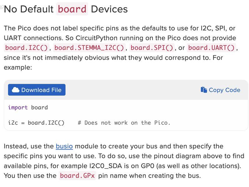
You need to use the “busio” module and specify which SDA and SCL pins you will use. This makes sense because accoriding to the Pico pinout, GP0 on the Pico can be used as RX, SDA and TX. So it would be correct to assume if we didn’t tell it how we wanted to use the pin, it wouldn’t automatically know what to do with it.
So, now the new problem this raises for me is I have no idea how to program in CircuitPython. I did some new reserach on this, and found that it is actually designed to “simplify experimenting and learning to program on low-cost microcontroller boards”.
I found a YouTube video from September 2020, where Dan from Adafruit Industries began a basic tutorial on how to get started with CircuitPython for CircuitPython Day! I knew it was a longshot, but I decided to give it a try. I followed Dan’s tutorial on how to install MU, set up my board and begin very basic entries to see if it would respond. I told it to add numbers, declare pins and finally make the LED on the Pico flash! It did. So far so good.
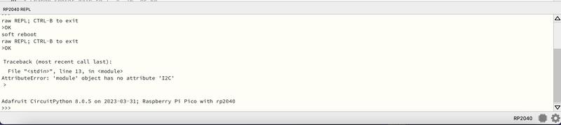
I continued his tutorials on how to call pins in code and worked through it until the end. Once I had this info, I decided to go back to the Adafruit site and copy the code they originally posted for the TCS34725 sensor. As I mentioned above, I didn’t know how to use Python, so I skipped over this section originally and went straight to the Arduino code. This time, I took the code and entered it into the code section of the Mu Editor. I saved it, loaded it to the attached Pico board and got an error.
I then used what I had learned above to make the necessary changes to call the pins I was going to use. I added the following lines to the code based on the origianl site that called the error in the first place.
import busio
i2c = busio.I2C(board.GP0, board.GP1)
I absolutely couldn’t believe it! IT WORKED!!!! I immediately began screaming so loudly that my husband came into the room to check if I was ok! I have never accomplished something so big! Well, at least it’s big to me!
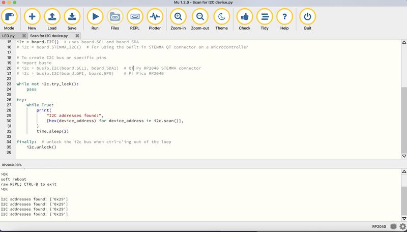
Below is the code to scan for any I2C devices connected to my XIAO. I used this site which gave me the code and instructions to plug it into CircuitPython.
# SPDX-FileCopyrightText: 2017 Limor Fried for Adafruit Industries
#
# SPDX-License-Identifier: MIT

"""CircuitPython I2C Device Address Scan"""
# If you run this and it seems to hang, try manually unlocking
# your I2C bus from the REPL with
#  >>> import board
#  >>> board.I2C().unlock()

import time
import board

# To use default I2C bus (most boards)
i2c = board.I2C()  # uses board.SCL and board.SDA
# i2c = board.STEMMA_I2C()  # For using the built-in STEMMA QT connector on a microcontroller

# To create I2C bus on specific pins
# import busio
# i2c = busio.I2C(board.SCL1, board.SDA1)  # QT Py RP2040 STEMMA connector
# i2c = busio.I2C(board.GP1, board.GP0)    # Pi Pico RP2040

while not i2c.try_lock():
    pass

try:
    while True:
        print(
            "I2C addresses found:",
            [hex(device_address) for device_address in i2c.scan()],
        )
        time.sleep(2)

finally:  # unlock the i2c bus when ctrl-c'ing out of the loop
    i2c.unlock()
As you can see in the image below, the code sent back a result of 0x29, which is the correct I2C device address for the TCS34725.
This is the code that worked for the sensor on the XIAO RP2040
# Write your code here :-)
# SPDX-FileCopyrightText: 2021 ladyada for Adafruit Industries
# SPDX-License-Identifier: MIT

# Simple demo of the TCS34725 color sensor.
# Will detect the color from the sensor and print it out every second.
import time
import board
import adafruit_tcs34725
#import busio
#i2c = busio.I2C(board.SDA, board.SCL)


# Create sensor object, communicating over the board's default I2C bus
i2c = board.I2C()  # uses board.SCL and board.SDA
# i2c = board.STEMMA_I2C()  # For using the built-in STEMMA QT connector on a microcontroller
sensor = adafruit_tcs34725.TCS34725(i2c)

# Change sensor integration time to values between 2.4 and 614.4 milliseconds
# sensor.integration_time = 150

# Change sensor gain to 1, 4, 16, or 60
# sensor.gain = 4

# Main loop reading color and printing it every second.
while True:
    # Raw data from the sensor in a 4-tuple of red, green, blue, clear light component values
    # print(sensor.color_raw)

    color = sensor.color
    color_rgb = sensor.color_rgb_bytes
    print(
        "RGB color as 8 bits per channel int: #{0:02X} or as 3-tuple: {1}".format(
            color, color_rgb
        )
    )

    # Read the color temperature and lux of the sensor too.
    temp = sensor.color_temperature
    lux = sensor.lux
    print("Temperature: {0}K Lux: {1}\n".format(temp, lux))
    # Delay for a second and repeat.
    time.sleep(1.0)
Wifi to Wifi Connections
One of the assignments for our lab was to make two wireless boards communicate with one another over Wifi.
I began by using this tutorial to learn how to connect a PicoW to wifi. The instructions were clear and easy to follow.
Once that was done, I used this tutorial to get two Pico W boards to connect and communicate with one another. I had a little bit of trouble trying to figure out how to connect to my phone, and still haven’t been able to figure that part out. However, running the code on my home wifi was simple to do followng the great instructions provided in the above tutorial.
Click the link for the file below to download all of the files I used in this week’s assignments. Files