5. Electronics production
This week I worked on milling a board designed by our electronics instructor. Once the board was milled, I stuffed it and then proceeded to program it.
Assignments for the Week:
Group Assignment:
Characterize the design rules for your in-house PCB production process
Extra credit: Send a PCB out to a board house
You can find our group work here.
Since I was in the lab most of this week, I milled several iterations of the linetest file. As a group, we then discussed what we found through the process.
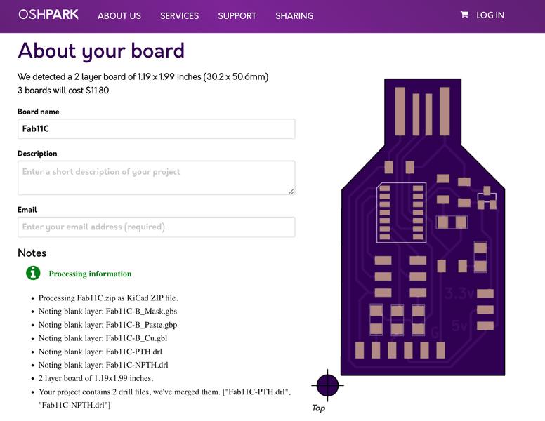
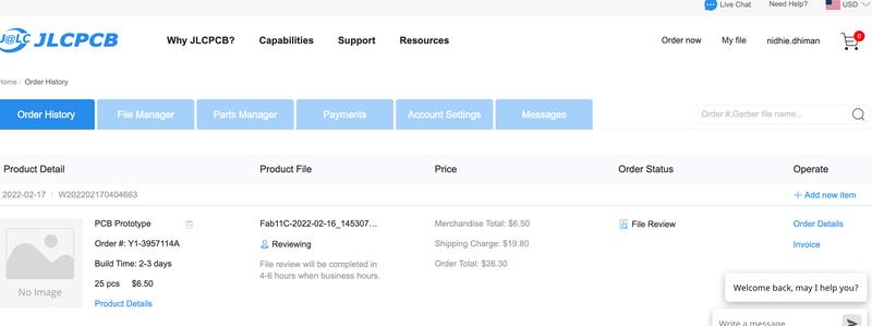
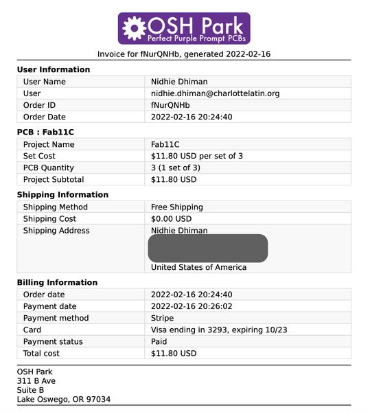
For extra credit, I also sent out PCBs to two different production houses. We wanted to see the timing difference and quality from two different locations. I chose the first one in the US (Osh Park) and the second in China (PCBWay). The process for each was fairly simple. You upload the files you want to use (mainly the Front and Cut files since we weren’t creating two-sided boards) and it walks you through the rest.
For Osh Park, there’s actually a button on their home page you can click and it will search for PCB files for you. Based on what it finds and you upload, it will calculate a price based on the design files. Super simple!
I had a little bit of trouble initially with the PCBWay order. But a quick email exchange with their customer support solved my issues. I was trying to load blank BACK files and didn’t realize it. Below, you can see our orders for both companies.
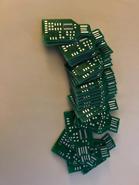
Here are the 25 boards we got back in! Surprisingly the order from China arrived before the US one. I discovered it was how they are able to keep their prices low. They wait to run a few small orders at Osh Park in order to save on their end, passing those savings on to you. To run 3 boards and have them shipped immediately would have been costly!
Individual Assignment:
Make an in-circuit programmer that includes a microcontroller. For extra credit, customize the design.
Mill and stuff the PCB
Test it to verify that it works
Practice
To prep for electronics production, we went through a weekly CLS (Charlotte Latin School) bootcamp along with our Fab Academy camp. Click here for more details involving our bootcamp projects.
Board Milling and Production
We practiced milling the Simple Fab-jtag2UPDI Board for our electronics production week. It is a board created by one of our instructors, Adam Harris.
In our lab, we use the original Bantam (Othermill) Desktop Milling machines and software. The milling process was something I had only briefly done before, in the Spring semester of 2021. I was really surprised by how much of it I remembered, but learned SO much more actually milling a board.
Until this point, our instructors gave us the correct bits to use for the boards. For this board however, one instructor simply said go mill this particular board - and walked out of the room! So I sat down and began walking through my workflow.
Setting up the board was fairly easy. I applied 3 full strips of Nitto tape to the back of the FR-1 board. I vacuumed the spoilboard of the machine and applied the prepped board to the lower left bracket corner. I then began to prepare the software to mill the board.
I opened the Bantam software and set the size of the board in the dimensions box. I entered the length, width and height (with the measurement of the Nitto tape). I also made sure the placement was set to “at left spoilboard origin” so it matched up with the actual placement on the board.

One of the really helpful settings on the Bantam is something called “Bit Breaker”. This built-in fuction allows you to calculate the thickness of your material. It is a PCB probing system that uses a conductive clip electrically connecting your PCB with the bed. Read more details here.
Next, I ran the BitBreaker and once it calculated the Z-height, I accepted the postion and it updated it in the “Thickness (Z)” position.

The next step was to open the file I wanted to mill and set it up for processing. I clicked on the “open file” button and selected the file I had saved on my computer. Next, I went through each part and selected the correct information. You can see in the picture below, when you first bring in the file, there are a lot of red lines, and the outline to be cut is at a point where the bit will hit the bracket.

So, I moved the placement of X and Y by 4mm each to move the design away from the edge, leaving space for it to correctly mill the outline. I unselected “holes” since I didn’t have any for this design file. Optionally, you could just leave that alone and it won’t really do anything. However, it’s good to understand that depending on what you actually want done (milling vs. outline vs. cutting holes) you can select those options here.
I then changed the milling tools until the red lines from the earlier image disappeared. I selected a tool for milling and for cutting the outline. The great thing about this software is it will mill the traces first and when that step is complete, it will stop and notify you to change the bit and continue with the rest of the job.
In the picture below, you can see that the design is now away from the edge of the plate and all of the red lines have been removed. This indicates the board is ready to mill.
One last step I did was change the “trace depth” and “trace clearance” to 0.25mm. While working with our milling machines over time, we have discovered this is our sweet spot!

Adding Components
Once I milled my board it was now time to “stuff” (add the components) and program it.
We usually begin by gathering the components from our lab and taping them to the appropriate locations on a printout of the board. We normally use a sheet of paper with the components listed out, however since there were multiple resistors and capacitors this time, I didn’t want to put the wrong one in the wrong location. I was unfortunately out sick this week, so my wonderful colleagues pulled my components and dropped them off to me so I wouldn’t fall too far behind! I printed out an image of the board and taped the components to where they actually appear when stuffed. This saved me a lot of trouble!

It took me a couple of hours to stuff my board. The chip was a little terrifying to look at with all those tiny little pins. Our instructors told us to learn how to “drag solder” to attach these types of chips to our boards. After watching several YouTube videos, I came across this one which was extremely helpful. Following this procedure I was able to solder my chip with minimal bridges between the pins and it was really quick! For the few I did have, I was able to solder sucker them right out to clean things up.
Another helpful trick was to use paste flux. My colleague and Fab Academy classmate, Scott Moulton, gave me a pot of it to use and it really is life-changing for me in the solering process.
Once my board was finished, I was excited to start programming it. And then I dropped it and PROCEEDED TO STEP ON IT when trying to pick it up! Those traces ripped right off because the portion I stepped on is where the headers were extruding out of the side. Hours of work ruined in a quick step!
There was no other option except to begin stuffing another board. Luckily I had duplicates of several components and the ones I did not have Scott offered to drop off once again, saving me from more lost time!
Board #2 was successful and I placed it on a towel in a safe space until I was ready to program it. OR SO I THOUGHT! I went to the lab with a colleague to program and test our boards as well as begin the process to test our milling machines. As soon as I plugged in my board it began to smoke! I ripped the wires out immediately to prevent any melting or further damage. I figured I had a short somewhere. But upon further investigation, I had YET AGAIN, soldered my chip on in the wrong orientation. I have this knack (apparently) of turning my board around to solder components and then I forget to put it back to my starting orientation so I know which way components with polarity go!
I am now keeping track to see which will take me down first - soldering components or documenting! There’s a 50/50 chance one of these will be the culprit of my engineering demise!
On to board 3! Third times a charm, right?
I stuffed board 3 without much hassle. Finding components in the lab was the hardest part. Once my components were all secure, I reviewed the documentation to program the board again. Following Adam Harris’ instructions I started by trying to get the blink code to light up on the new board using an Arduino.
Programming the jtag board
The programming of the board proved to be the hardest part yet. Our group, instructors and electrical instructor tried throughout the week to program it without success. Knowing we had to complete this assignment to be able to complete future weekly assignments for electronics, we were told to “table” this board. Hoping our instructors can troubleshoot and find out what might be wrong, I would like to come back and finish this board at a later date (even if after Fab Academy).
Creating the SAMD11C
We quickly changed gears and began milling our new boards. Our instructors chose the SAMD11C for us to create. Lucky for us, we used this design in the extra credit assignment when we sent a design to the board houses. We initially did this thinking we could use it as a teaching opportunity in our classes, but these boards came in handy immediately.
I took a layered approach to finishing this process. Since I had the professionally milled boards, I decided to try to stuff and program one of these boards first to make sure programming it would not be a problem. The board is a lot smaller and had fewer components so I was able to stuff it in about 30 minutes. Once I stuffed it, I began the programming process.
I learned from our instructors that the ATMEL Ice programmer was giving the other groups a lot of issues. New cables were ordered for the programmer, and it is believed they are incorrectly labeled or have an internal issue. So, I used the SAMD to SAMD method to program my new board.
I followed Adam Harris’ method on his Sheek Geek website to set up the board for programming. Since I already had access to a board that had been “ICED”, I set up my target board.
Of course I did so incorrectly. For half an hour, my colleague Barbara Morrow and I tried to program our boards. We could not, not matter what we tried, get the bootloader onto them. We kept getting the same error of “no debugger”. As the frustration built, one of our Fab Academy students walked by and saw we were having trouble.

Within seconds, he noticed that we had actually set up the boards in the wrong order. Most of the time, when have set up boards for programming, the programmer has been on the left and the target board on the right. I set up the boards in the same manner. However, right on our screen in GIANT pink letters, the left board was titled “TARGET BOARD”. In the picture below, we accidentally set up the Target board on the right, instead of the left.

After changing the cables to the correct orientation, I was able to program my board within seconds with the bootloader! After this successful step, and very carefully reading all the instructions that followed, I was able to successfully blink my ATtiny412 with my new SAMD11C programmer.
Now that I knew I could actually program it, I set out to do the same on a board I actually milled. Following the same procedure used above to mill the ATmega, I milled the SAMD11C board. I stuffed the board and then set out to make it into my programmer.
To begin, I downloaded the edbg and SAMD11 bootloader core firmware from Adam Harris’ website. One thing to take note of is to make sure to note what version of the edbg file I was using as this will be important in the next few steps.
This time, I set up the boards correctly, with the target board on the left and the SAMD programmer on the right. After confirming this step, I then opened my command prompt and added the following code:
edbg-windows-r24.exe -bpv -e -t samd11 -f sam_ba_Generic_D11C14A_SAMD11C14A.bin
I then plugged in each board into a usb port on the computer. Remember to select the 3.3V on the regulator switch to begin this step! Once plugged in, I hit enter on my command prompt. Everything was successful this round, and the command prompt produced the correct results.
Now that the bootloader is on the target board, I needed to make sure Arduino is able to recognize and access the board. To start, add the following to File –> Preferences –> Additional Boards. If you already have other boards listed, click on the icon next to the box, and you can add multiple boards.
https://www.mattairtech.com/software/arduino/package_MattairTech_index.json
Then, open the Boards Manager under Tools and search for “MattairTech SAM”. This process will take a few minutes to load. Once loaded, use the following to make sure all of your selections for the board are correct. It is very important to select “INTERNAL_USB_CALIBRATED_OSCILLATOR” whenever the board is plugged into the usb port of the computer.

The next step now that I had the bootloader onto my board was to get it to blink. I again used our trusty Blink code in Arduino. The code (below) uses pin 2 in Arduino, which correlates to pin 13 on the SAMD11C. Plug in just this board into the usb port and upload the following code.

int led = 2;

// the setup routine runs once when you press reset:
void setup() {
  // initialize the digital pin as an output.
  pinMode(led, OUTPUT);
}

void loop() {
  digitalWrite(led, HIGH);   // turn the LED on (HIGH is the voltage level)
  delay(1000);               // wait for a second
  digitalWrite(led, LOW);    // turn the LED off by making the voltage LOW
  delay(1000);               // wait for a second
}
My board blinked! Now, it was time to turn it into a UDPI programmer so I could use it to program the ATtiny412. To do so, I uploaded the following code in Arduino. Again, nothing else is plugged into the board.
void setup() {

   SerialUSB.begin(0);
   Serial1.begin(57600, SERIAL_8E2); //Adjust baud rate and use SERIAL_8N1 for regular serial port usage
}

void loop() {
   if (SerialUSB.available()) {
      Serial1.write((char) SerialUSB.read()); //Send stuff from Serial port to USB
   }
   if (Serial1.available()) {
      SerialUSB.write((char) Serial1.read()); //Send stuff from USB to serial port
   }
} //end loop
At this point, this board is now a UDPI programmer. To test it, I used the ATtiny412 board I made in our CLS bootcamp. In Arduino, the most important step is to change the board to ATtiny412! If you don’t do this step, you are essentially writing over everything you’ve done so far, and will need to re-program your programmer.
Once the board was changed, I connected the SAMD11C programmer to the ATtiny412 using the method in the image below:

And it was very important to use the wire as a jumper. This is how it is able to program using UDPI.

Next, I used the blink code, set it to pin 0. I changed the programmer to SerialUPDI – SLOQ: 57600 baud, any platform and plugged my SAMD board into the usb port once again. I then uploaded the code and voila - nothing happened! Once again, I quickly realized I hadn’t selected the correct port. After changing the port to the one that corresponds to my board I uploaded it again. This time it worked successfully!
Blink Code: Generic Arduino
Built into the Arduino software are examples of code. One of the most common test codes is the “Blink” Code. For this project, we used the Blink code once our programmer was working. The standard code is below. One of the things we had to do was chage the pinMode from LED_BUILTIN to the pin we were using on the chip. To determine which pin to use, we read the pinout diagram for the particular chip we are using.

// the setup function runs once when you press reset or power the board
void setup() {
  // initialize digital pin LED_BUILTIN as an output.
  pinMode(LED_BUILTIN, OUTPUT);
}

// the loop function runs over and over again forever
void loop() {
  digitalWrite(LED_BUILTIN, HIGH);   // turn the LED on (HIGH is the voltage level)
  delay(1000);                       // wait for a second
  digitalWrite(LED_BUILTIN, LOW);    // turn the LED off by making the voltage LOW
  delay(1000);                       // wait for a second
}
Here is my board blinking!
Click the link for the file below to download all of the files I used in this week’s assignments. Files