Final Project
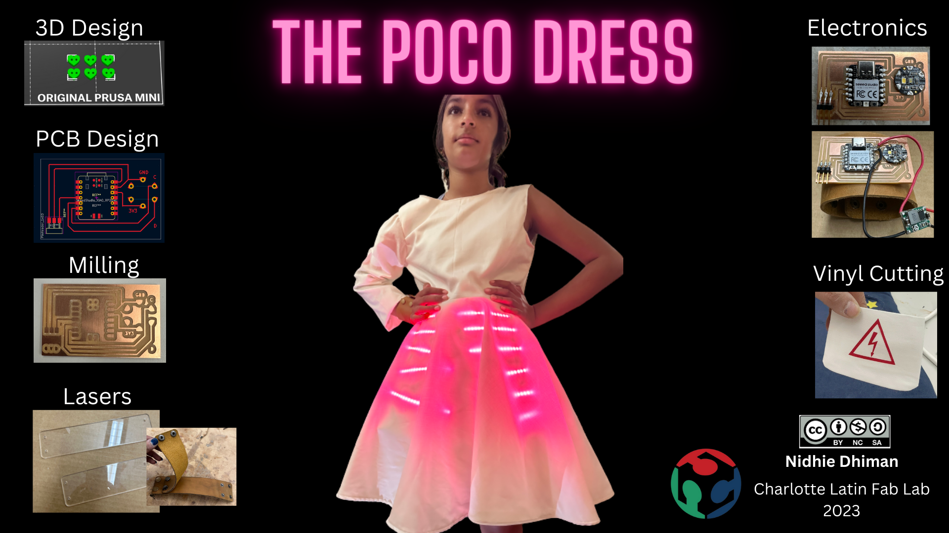
Final Project Slide
Final Project Video
When I found out last year that I would be enrolling in Fab Academy 2022, I had a rush of emotions. Nervousness, excitement, more nervousness, fear…it was a little bit of a roller coaster for a while. Still on that ride, by the way!
One things I have known since then, is a project I wanted to create. I remember having a discussion with my 12-year-old as we were selecting her classes for 7th grade. She was interested in trying the school’s Innovation and Design class, but she already had some predefined notions of it in her mind - and of engineering in general. She is artistic and was curious to how engineering could be incorporated in art, interior design or any other field she chooses. I am determined to show her no matter what she chooses for her future, engineering can play a role in it!
We talked a lot about my idea for my project together. Ever since then, she has been intrigued. She loves clothing, and fashion, music, dance…and TikTok (of course). I presented the idea to her about using the fashion she sees online, and “add engineering to it” to create not only something beautiful, but something that shows how the two worlds can merge to create something even more interesting.
So, my project is to create a reactive dress. My plan is to have it respond to sound, and try to create an equalizer effect in the bottom of the skirt. With the love we both have for dance, I absolutely want it to light up to music. I am still exploring other options for input as well.
Once I decided on an idea, I did a lot of research to see what was already out there. I want to include much of the machinery we have in the lab to create the dress, and can’t wait to get started!
My rough sketch of my dress is below. There is still a lot to plan out, but I believe this is a start in the right direction. I know it will evolve, and in the end it might not even look or do what I have planned right now, but that is also probably to most exciting part of this journey. As I learn more over the next few months, I hope to apply my new knowledge to my design!

Research
I looked into using a video compressor because as of this new Fab cycle for 2023, we are no longer supposed to use YouTube or Vimeo to host our personal videos. I tried a few different ones and didn’t care for them. I landed on using FVC free video converter online. Everything is done online and is quick and easy to set up.
You can click here to download and install it.
I have saved my videos as MOV files and running them through the compressor takes just a few seconds. It then downloads them to a folder you specify. Once they are in my “compressed” folder location, I move them to the folder for my Visual Studio files and begin loading them.
3D Design - Fusion 360
Because I do not have extensive experience with using Fusion 360, I completed several YouTube tutorials designed by Kevin Kennedy. (link: https://www.youtube.com/c/ProductDesignOnline). He has a “Learn Fusion 360 in 30 Days” lesson plan and I specifically tried to select lessons that could possibly help me when designing my own project. I looked for varying tools he uses, and methods for tracing, drawing and adding dimensions.
To begin some actual design work for my own project, I decided to start with the gems for the jewelry I hope to create to go with the dress. I am picturing a bracelet or necklace, possibly made on the 3D printer but I would add a different color gem to the setting. I searched around until I found a piece I liked the shape of, but could manipulate and flatten out to my liking. I used this (https://www.youtube.com/watch?v=pkgfp_rrbkQ) tutorial from MAD’ About Designs to create the basic shape of the diamond. This is his original design: (original diamond shape is the filename)
In following his tutorial, I began by selecting the top plane and sketching a polygon with 12 sides and a radius of 5mm.

Once I finished the sketch, I then selected ‘E’ for the extrude tool. I extruded the bottom of the polygon and tapered it to -45 degrees and a depth of 5mm, as in the video. I realized I wanted a flatter bottom, rather than the diamond point from his design, so I changed the distance to only 2mm.

The next few steps were all the same, but at varying degrees and depths as the previous step. These extrusions helped create the top of the gem.

The next step was to facet the sides of the gem to look more like a diamond cut. In order to do this, I had to create an offset plane using 3 points. The 3 points selected were on the final extrusion and, when cut, will give the faceted look we needed to achieve. In the picture below, you can see the 3 points selected, as well as the yellow plane created that runs at an angle to the component itself.

The next step is to cut away the triangle shape created from the plane and 3 points. This gave me the first facet on the top layer.

To run the facets all the way around the top of the piece, I used the pattern tool. You change the type to features and then use the timeline below to select the last feature created, which was the triangle on the new plane. Once that is selected, you select the center axis to rotate the pattern around and enter in the number of points to duplicate (in our case 6).

The final step is to add an appearance to the project, but I did not keep this step after I did it. Here is the final piece.

Updated Planning and Design Ideas
The dress is in full swing, however, I think I am changing ideas on what I want the dress to actually do! During COVID our world turned upside-down. My daughter struggled with it a lot; not being able to see her friends, socialize and basically being held captive in our home. When we slowly starting coming back to “normal”, we still had to keep our distance. Now, I think our family appreciates, as do many others we’ve talked to, the happiness and joy we feel by being in close physical space with our friends and loved ones.
I want to celebrate that closeness with the COVID dress. My kiddo actually helped me come up with the idea when I was sitting around frustrated last weekend that I couldn’t get my sound sensor to work! So, now, my dress will still light up, but the new idea is to use a color detecting sensor and have the lights change color based on what the person standing next to you is wearing.
Reworking the Input and Output
Now that I had changed course on my sensor, it was time to figure out to how to add my sensor as my input. I reviewed the Adafruit site and they had a great tutorial on how to use the sensor and the code. Remember I learned during my Embedded Networking (week 15) that I couldn’t use my sensor in an easy way using Arduino and the XIAO or Pico. I went through a few tutorials to learn just enough basics to use MicroPython in MU Editor.
I copied the following code from the Adafruit webiste:
# Write your code here :-)
# SPDX-FileCopyrightText: 2021 ladyada for Adafruit Industries
# SPDX-License-Identifier: MIT

# Simple demo of the TCS34725 color sensor.
# Will detect the color from the sensor and print it out every second.
import time
import board
import adafruit_tcs34725
import neopixel
#import busio
#i2c = busio.I2C(board.SDA, board.SCL)

# On CircuitPlayground Express, and boards with built in status NeoPixel -> board.NEOPIXEL
# Otherwise choose an open pin connected to the Data In of the NeoPixel strip, i.e. board.D1
#pixel_pin = board.NEOPIXEL

# On a Raspberry pi, use this instead, not all pins are supported
pixel_pin = board.D6

# The number of NeoPixels
num_pixels = 5

# Create sensor object, communicating over the board's default I2C bus
i2c = board.I2C()  # uses board.SCL and board.SDA
# i2c = board.STEMMA_I2C()  # For using the built-in STEMMA QT connector on a microcontroller
sensor = adafruit_tcs34725.TCS34725(i2c)

# Change sensor integration time to values between 2.4 and 614.4 milliseconds
# sensor.integration_time = 150

# Change sensor gain to 1, 4, 16, or 60
# sensor.gain = 4

# Main loop reading color and printing it every second.
while True:
    # Raw data from the sensor in a 4-tuple of red, green, blue, clear light component values
    # print(sensor.color_raw)

    color = sensor.color
    color_rgb = sensor.color_rgb_bytes

    print (color_rgb[0])
    print (color_rgb[1])
    print (color_rgb[2])
    print()
    time.sleep(2.0)

pixels.fill((0, 0, 0))

# The order of the pixel colors - RGB or GRB. Some NeoPixels have red and green reversed!
# For RGBW NeoPixels, simply change the ORDER to RGBW or GRBW.
ORDER = neopixel.RGB

pixels = neopixel.NeoPixel(
pixel_pin, num_pixels, brightness=0.2, auto_write=False, pixel_order=ORDER
)

# Comment this line out if you have RGBW/GRBW NeoPixels
pixels.fill((color_rgb[0], color_rgb[1], color_rgb[2]))
# Uncomment this line if you have RGBW/GRBW NeoPixels
# pixels.fill((255, 0, 0, 0))
pixels.show()
time.sleep(1)
I added it to the MU editor and ran it. The sensor still worked as I expected.
CAPTURE THE VIDEO OF JUST THE SENSOR WORKING
Next, I plugged in a short strip of neopixels (7 pixels) to the XIAO and made sure the pixels still worked. Adafruit’s CircuitPlayground Express had the code I needed and I pasted that into my MU Editor. That code is below:
# SPDX-FileCopyrightText: 2021 ladyada for Adafruit Industries
# SPDX-License-Identifier: MIT

import time
import board
import neopixel


# On CircuitPlayground Express, and boards with built in status NeoPixel -> board.NEOPIXEL
# Otherwise choose an open pin connected to the Data In of the NeoPixel strip, i.e. board.D1
#pixel_pin = board.NEOPIXEL

# On a Raspberry pi, use this instead, not all pins are supported
pixel_pin = board.D6

# The number of NeoPixels
num_pixels = 7

# The order of the pixel colors - RGB or GRB. Some NeoPixels have red and green reversed!
# For RGBW NeoPixels, simply change the ORDER to RGBW or GRBW.
ORDER = neopixel.GRB

pixels = neopixel.NeoPixel(
    pixel_pin, num_pixels, brightness=0.2, auto_write=False, pixel_order=ORDER
)


def wheel(pos):
    # Input a value 0 to 255 to get a color value.
    # The colours are a transition r - g - b - back to r.
    if pos < 0 or pos > 255:
        r = g = b = 0
    elif pos < 85:
        r = int(pos * 3)
        g = int(255 - pos * 3)
        b = 0
    elif pos < 170:
        pos -= 85
        r = int(255 - pos * 3)
        g = 0
        b = int(pos * 3)
    else:
        pos -= 170
        r = 0
        g = int(pos * 3)
        b = int(255 - pos * 3)
    return (r, g, b) if ORDER in (neopixel.RGB, neopixel.GRB) else (r, g, b, 0)


def rainbow_cycle(wait):
    for j in range(255):
        for i in range(num_pixels):
            pixel_index = (i * 256 // num_pixels) + j
            pixels[i] = wheel(pixel_index & 255)
        pixels.show()
        time.sleep(wait)


while True:
    # Comment this line out if you have RGBW/GRBW NeoPixels
    pixels.fill((255, 0, 0))
    # Uncomment this line if you have RGBW/GRBW NeoPixels
    # pixels.fill((255, 0, 0, 0))
    pixels.show()
    time.sleep(1)

    # Comment this line out if you have RGBW/GRBW NeoPixels
    pixels.fill((0, 255, 0))
    # Uncomment this line if you have RGBW/GRBW NeoPixels
    # pixels.fill((0, 255, 0, 0))
    pixels.show()
    time.sleep(1)

    # Comment this line out if you have RGBW/GRBW NeoPixels
    pixels.fill((0, 0, 255))
    # Uncomment this line if you have RGBW/GRBW NeoPixels
    # pixels.fill((0, 0, 255, 0))
    pixels.show()
    time.sleep(1)
As expected since I was able to run this code before, it ran again with no issues. Here is a quick video of that code working.
Off the Cuff
One of the longest design questions was how/where to mount the sensor so it makes sense, but also isn’t obvious in the design. I wanted the dress and lights to be the focus and the sensor almost a non-existent piece!
I viewed several options online of how creators of wearables hid their sensors or made them fuctionable. I came up with the idea of adding a leather cuff to the dress, which also made sense to me considering I needed a way to hide the wiring. This is when I also added the idea of the sleeve on one side, giving the dress an asymmetrical look.
I ordered some inexpensive faux leather to test out, along with some button snaps I thought would look good. I knew I couldn’t cut the leather in the laser because it was made out of PVC, so I hand cut it using a template I created on cardboard. The faux leather was easy to use, but one of the problems I encountered was it was so thin, it didn’t hold the button snaps well.
Combining the input and output
Taking what I was able to accomplish from the above sessions, now it was time to try to combine them together and get them working for my final project.
I copied the code for the sensor into a new window to begin the process. Next, I copied each section of the code for the neopixels and put them in the appropriate code section in the new window. For example, defining parameters I put towards the top and the section that needed to be looped I put into the “while” loop.
The original code for the neopixels cycled through a few options, and I know I didn’t need all of those. So I removed the “rainbow” lights section and I also deleted 2 of the 3 sections when it cycles through R, G, B.
Once I had the sections I didn’t need deleted, I ran the combined code just to see what it would do. It didn’t do anything. It looked like the code “loaded”, but the REPL just did a soft boot and went back to the prompt.
I put the code in ChatGPT and asked it what the code would do. As expected it responded with the sensor would pick up the color of the item held close to the sensor and the LEDs would change to that color. But, I couldn’t get it to work. I tried to view it line by line to see if I could follow what was going on. In my limited coding knowledge, it looked correct to me.
So, after about an hour of no sucess, I polled colleague Adam Durrett to view my code. I explained to him that I had two working codes that did what I needed them to do, but after staring at the combined code for a while, I can’t find what I’m overlooking. Adam was a huge help and after looking over the code for a few minutes, he found a line I had in the loop that should not have been there. It was in the loop of the original LED code, but it made sense there because it reset it when it was ready for the next display of colors. In my combined code, however, it was resetting the LEDs every second, essentially never changing them!
I moved the line out of the loop and tried to run again. This time in the REPL I started to see the numbers from the sensor on the screen and the lights began to change! It worked!
Great! The next step for me is to create my board and see if I can get it to work with the soldered components.
I designed a simple board in KiCad with my sensor, a XIAO and some header pins to attach my LEDS to. I wanted to confirm I could get it to work with just a few neopixels. Remembering what I learned early on during this course, I knew I could safely light up 8 neopixels using my computer.
PIC OF FIRST MILLED BOARD
The hardest part of milling my board was getting my sensor footprint on the pcb. When I loaded the KiCad files for the TCS34725, it brought in the entire completed board. Even though I had set up the nets correctly in the schematic, when I moved over to begin working on the pcb, I couldn’t get the traces to attach to the correct pads. I finally learned from Adam Durrett that I could just copy the parts of the sensor board I needed and paste those onto the board. Once that was done, I was able to double-click on each pad and reassign the net to the new option. A few clicks to save the gerber files and I was ready to mill.
Using the methods I learned during electronics production, I was able to mill my board pretty easily!
Wireless Options - Version 2.0 currently in progress
Using the wireless work I did during networking week, I continued to view more tutorials to get a better understanding of how it works and how I could possibly manipulate it to work for my final project. I want to continue to work on the project, redesigning it and adding improvements!
One of the first things my daughter and I talked about for the next step is to make the sensor wireless. It was a little cumbersome for her in not being able to move her arm as far out as she wanted to. The wires are currently tacked to the inside of the long sleeve on one side of the dress and the sensor is in the cuff, limiting her mobility.
I started by trying to find out if there is an actual way for me to learn to manipulate the RGB color input of a neopixel strip over wifi. I found an Adafruit tutorial to use a neopixel strip and a website called Adafruit IO to use sliders to change the R, G and B values and send them to the Pico W board attached to the strip. The tutorial to set up the strip and code is here and the Adafruit set up is here.
I am still also working on setting up an external power source to run the PicoW without power, yet still have it connect to wifi and run the loaded program. I used this website and learned that you actually need to name the file you plan to use as main.py in order for the board to know to begin it on power startup.
I was able to do this with a simple LED code (naming the file main.py) to flash the built-in LED with an external power source. The light came on and began flashing as soon as I plugged it in to the power bank. However, I can’t get it to work with the code above just yet (as of 5/10/23).
import time
import board
import adafruit_tcs34725
import neopixel

# On a Raspberry pi, use this instead, not all pins are supported
pixel_pin = board.D6

# The number of NeoPixels
num_pixels = 7

# Create sensor object, communicating over the board's default I2C bus
i2c = board.I2C()  # uses board.SCL and board.SDA
# i2c = board.STEMMA_I2C()  # For using the built-in STEMMA QT connector on a microcontroller
sensor = adafruit_tcs34725.TCS34725(i2c)
pixels = neopixel.NeoPixel(
        pixel_pin, num_pixels, brightness=0.5, auto_write=False, pixel_order=neopixel.GRB
    )
# Main loop reading color and printing it every second.
while True:
    color = sensor.color
    color_rgb = sensor.color_rgb_bytes

    print(color_rgb[0], color_rgb[1], color_rgb[2])
    print()

    # Comment this line out if you have RGBW/GRBW NeoPixels
    pixels.fill((color_rgb[0], color_rgb[1], color_rgb[2]))
    # Uncomment this line if you have RGBW/GRBW NeoPixels
    # pixels.fill((255, 0, 0, 0))

    pixels.show()
    time.sleep(0.5)