14. Input Devices
You can view our results for our group assignment here
Reflection to this point
About 3 weeks ago, something changed. I wasn’t terrified of Fab Academy anymore. Don’t get me wrong, it’s still crazy every week trying to learn the things I need to know to figure out assignments, but it’s getting easier now. Maybe things are starting to sink in? Maybe I realize that I can’t possibly know everything there is to know, but I’ve learned where to look for the info and how to dig deeper to find it? Did I read the datasheet? Did I confirm my traces in KiCad were the correct width? Did I correctly ground everything? I never thought I would be desiging and milling circuit boards, but here we are!
Regardless of what is making me feel this way, it is a welcome feeling!
Input Board
To start off this week’s assignment, I began by reviewing Neil’s boards for sound. They looked simple enough and nothing too terrifying. Instantly one of the things I knew I would have trouble with is using the reflow method to mount my MEMS sound sensor. I also, at this point, hadn’t figured out how to add “extra” components to a board. How do I know that I need a certain resistor or two capacitors like he had? This assignment revealed a lot of answers to this question!
When I spoke with Adam Harris about this week’s assignment, we reviewed the sensors we already had in the lab. The sound sensor we carried in stock had a port on the bottom, so I would have had to mill a port hole in my board. We also did some research on which IC would work best for this given that he really wanted me to study using I2S for my communication.
Once we scoured the internet, and he gave me some research homework, we found a few sites that would help me complete this assignment.
I still knew nothing about I2S. So, I did a little more research. We found this site by Fab student Shinobu Ishimura from 2021. On his page, he discussed the use of the ATtiny1614 because it has I2S capability.
I also reviewed this article from HACKADAY which gave me some basic background knowledge on this method.
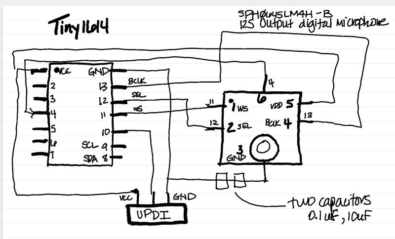
To begin, we thought it would be best if I attempted to use the sensor we had in stock. I started by pulling the datasheet for the old sensor we had in the lab. The SPH0645LM4H-B datasheet was pretty short and easy to get through. Adam and I thought it best for me to work with an ATtiny1614 to begin with. So I grabbed my info and sketched out a quick design of what I thought my board would look like.
I quickly realized after speaking to Tom Dubick that the port on the bottom of the sensor might prove difficult. So, he quickly ordered the CMM-4030D from Digikey while putting in an order for other parts.
I reviewed the datasheet for CMM-4030D to understand how to set it up with my board.
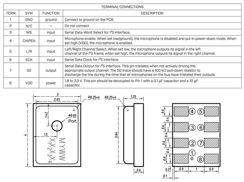
Earlier I mentioned not knowing how to figure out what extra components I would need for my board to run correctly. The datasheet helps lay this out. In the above terminal connections, it told me I would need “a 100 kΩ pull-down resistor” on the SD trace. I also will need a regulator, as the voltage is 1.8 to 3.3V. And finally, the VDD pin should be decoupled to Pin 1 with a 0.1 μF capacitor and a 10 µF capacitor.
All of this reflects the boards both Neil and Shinobu designed. But now, they made sense. I wasn’t just copying a board and milling it out. I understood why the components needed to be there and thier functions.
Now I could mill my board. Because I understood the design, for the first part of this step, I just used the provided traces and interior png files from Neil. I imported them into Corel Draw, converted them to single color svg images that our Bantam software could recognize and prepared my files in Bantam. To see how I completed this process, review my work from Week 5.
Once I had the board milled, I needed to solder my components. I had never soldered a component using reflow before, so this was something I needed to research. I also spoke to Barbara Morrow and Tom Dubick, who both helped my understand how the paste method worked. I’ve always said the reflow heat gun scares me a little, but I’ve watched Tom use it plenty of times, so I decided to give it a try.
It didn’t take long for the gun to heat up. I had already applied a thin layer of paste to the bottom of the sensor where the pads are. The most difficult part, is lining everything up. I did this, and then made sure that when I was applying the hot air, I didn’t turn the airflow up too high so the component would move, but it had to be high enough to get the heat there. So tricky!
It actually soldered very easily to my surprise. I could see the paste run along the traces coming out from underneath the sensor. There was a small part of me that wondered if it was in fact on the pads, or if it had moved at all during the process. I decided to move forward and see if I could load the program onto it. I added the remaining components and set off to program my new input board.

Lucky for us, Neil provided the ino file for the sensor. I loaded up the program in Arduino IDE and nothing happened, except my board began warming up!
Issues
I ended up having the same problem we had during Week 9 when we did embedded programming. It was during this week that we discovered our issue with the 3.3V regulators and the change in the manufacturing of the component. Now, because of supply chain issues, we have been unable to order any of the same parts.
During our digging around, we came across another regulator, just with a larger footprint. I needed to verify that it would work for what I needed it to do. So, I set up the component on a power supply and set it to 5V. I then probed the ground and pin out to check to see that it indeed was regulating down to 3.3V. It worked here, so I set out to connect it with jumper wires to see if I could get it working on my board.
I had quite a bit of trouble loading the footprint to KiCad for this regulator. I downloaded the sensor ones and had no trouble, but this one kept giving me an error. I thoguht it might be an issue with the file I downloaded, so I move to SnapEDA to get the file. Again, I had trouble using the same method. Took me a while to figure this out!
Another concern I had was that the sensor had indeed moved during my reflow process. I was disussing with some other Fabbers on how to correct for this, since none of us had reflow soldered before. Aaron Logan had a great idea for me to quickly cut the outline of the board and a small cut into the carboard for the outline of the sensor. I could then tape the “jig” to the board and place the sensor into it.
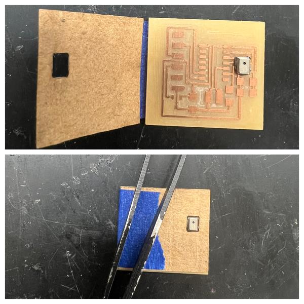
I thought it was worth a shot, so I cut it out and applied it to the second board I had already milled. This process made me feel a little better that the sensor might be right on the mark this time!
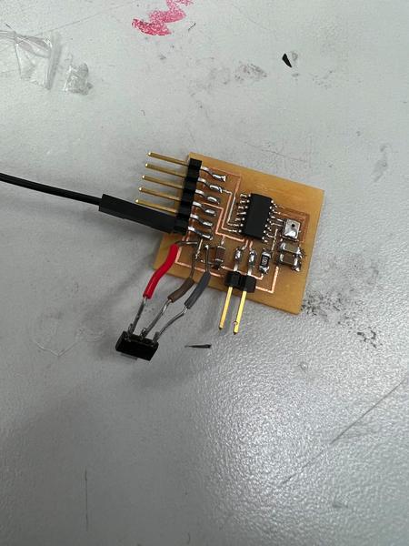
Before stuffing another board, I decided to try out the one I had modified with the jumper cables. Although it didn’t work perfectly, I was at least able to get a connection to the board in the serial monitor. You can see in the video below, that there are still issues to work through, but it was trying!
Click the link for the file below to download all of the files I used in this week’s assignments. Files