12. Mechanical Design and Machine Design (off Week 13)
For our group project, we are building an asset management machine to keep track of the milling bits in the lab. During week 5, electronics production, we learned a lot about the different types of bits we house for PCB milling. We learned even more during week 10, molding and casting, when we used different types of bits to mill our wax blocks.
Throughout this time, we have learned a few issues the lab faces when dealing with these types of bits:
-
Each bit is an investment, ranging anywhere from $15-$30 PER BIT
-
Depending on the usage of the bit, many of them run out after one use (this is especially true of the bits with very fine tips)
-
Sometimes, working with MS and HS students, we have an issue with bits being properly returned to their original containers.
Hearing all of these issues, Charlie Horvath and Barbara Morrow originally thought of the idea during one of these previous milling late night work sessions. Both then presented to the group and the majority of the group loved the project. The only worry was would we be able to pull it off in the short timeframe. This would be a great device for the lab, so Barbara Morrow and I thought if we could get a proof of concept at least working, then we could continue tweaking it for full time use in the lab.
With that, our idea was born!
Assignments:
Mechanical Design (part 1 of 2)
Group Assignment:
- Design a machine that includes mechanism + actuation + automation.
- Build the mechanical parts and operate it manually.
- Document the group project.
Individual assignment:
- Document your individual contribution.
Machine Design (part 2 of 2)
Group assignment:
- Actuate and automate your machine.
- Document the group project
Individual assignment:
- Document your individual contribution.
Reftab Software
Charlie found a a few websites for asset management and had me review the one he liked the most, Reftab. I took the task of working through the software as my main job, along with working with Barbara to get the stepper motor working, the bits boxes printed and labeled, the door and iPad holder and anything else that came up.
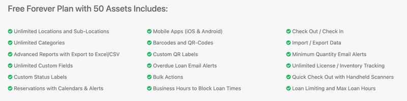
I began by setting up a free account in Reftab. They offer a lot in their free version. I began with the assumption we would begin this project as a proof of concept and didn’t need to add everything in the Bantam library as an asset to begin with. So, their free verion with a total of 50 assets worked perfectly for this project.
With this same version, we are able to customize information required for the assets, run reports, create “loanees” to use the assets and much, much more! Even if we decide to pay for this later on in the lab, the monthly cost is the equivalent of saving 2 bits, so it’s well worth the investment in our opinion.
Once the account was set up, I decided it would be best to speak with Zack Budikowski, who manages our materials and machines in the lab. I asked him for a listing of our most common bits for PCB milling (to make sure I accounted for them all) and if possible to pull purchase information so we can track when we purchased and added them to the system. Should we choose to keep just the trial version, we also talked about instructors just back-filling and resetting the assets in the software when a new bit was needed.
Another exciting piece for Zack was that moving forward, we can set up and capture data for how long a bit was used. This way, we can eventually track the lifespan of the bit and see how quickly we are using them up.
In order to better understand the software and what it provides, I set up a brief meeting with one of the creators. When we met, we discussed how the software works, the types of reports we could run and most importantly for our group, how to incorporate our students into the system. One of our main goals when we discussed the software as a team, was that we didn’t want to have to have students set up separate accounts to use the sytem. He was able to help me understand how to set them up as “loanees” on the back end so they would not have to.
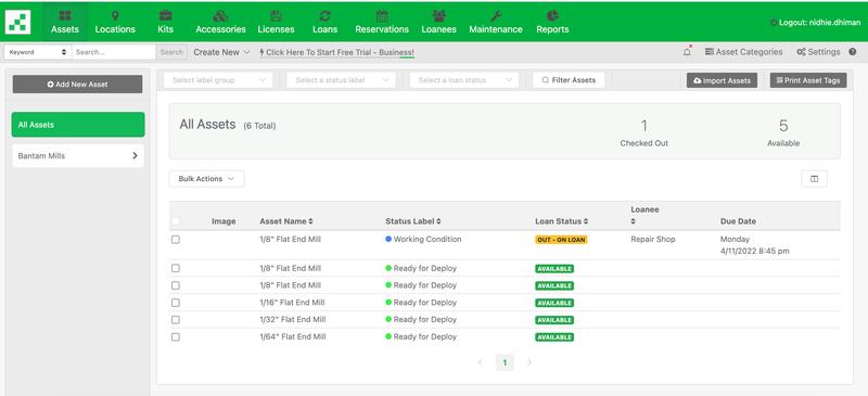
Once I completed the call with him, I was able to confirm we were using the software correctly. I chose to use the “Asset” tab to log our bits since this allowed for idividual tracking/coding of each one. I quickly set up a few sample items into the Assets category so I could practice with user inputs and on the app. After setting up assets, I needed to add some “Loanees” to the list. I used several colleagues and a few test students from my classes/Fab Academy.
Test Loans were then performed on a few of the bits in the system. The image below shows the checkout of one of the bits on the main assets page. At this point, I had checked a few assets in and out to make sure the sytem captured everything.
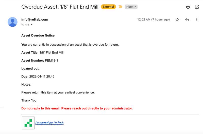
Overdue Asset emails are automatically sent by the sytem to anyone who has not turnd in an asset by the end of the (24 hours). I purposely left one asset open to test the email system and at 12:02am, I received the following email reminding me to turn in my asset.
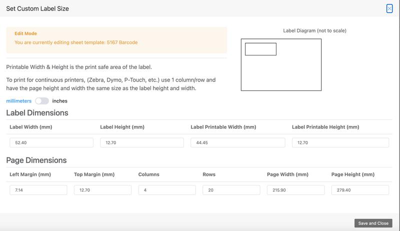
Once we were done with adding the assets we wanted to use into the system, I set up the barcode labels. We planned on using these labels on the sides of the boxes to make check-out/ check-in quicker and easier. You can actually customize the labels to the size and information needed. For our purposes, I changed the size to the built-in Avery label size for return address labels. I didn’t use the actual labels because the size was too big for our boxes, but the print size of the barcode fit perfectly. So, we quickly cut the barcodes out and adhered them to the boxes.
In our original idea, Charlie and I talked about making returning the bits boxes foolproof. We were planning to put the barcode on each side of the boxes. That way, no matter what orientation the box was returned, the barcode was scannable. However, the design of the box was so precise and fit into the holder very snugly. So, for this version, we opted to put the barcode just on one side and made note of it in the workflow.
Stepper Motor
During the first half of the week, Barbara Morrow and I ended up working on the NEMA17 stepper motor together. Barbara is using the motor in her final project, so she spent much of the week/weekend trying to work on it with various shields. I just wanted a better understanding of what we were using in our group project, and just did a little research on my own.
When we were both in the lab working, we realized we had a lot of the same notes and even ended up on the same GitHub site with all of the files we would need to get our motor working. So, it just made sense to use the smaller motor driver, the L298N, to get it all working, since we would only need 1 motor for the wheel design.
“This final site” was incredibly helpful in how to wire the NEMA17 Stepper Motor to the L298N Motor Driver. The video originally showed how to connect two motors to the motor driver, but we were able to take those steps and create the proper connection for just one NEMA17. We were really excited when the boards lit up, and the motor jerkily vibrated for a few seconds before turning off and the light going off on the motor driver.
We tried fixing this by making sure all of our connections were tight and where they needed to be. The code loaded with no issue, so we didn’t believe it to be a software concern. After several attempts to remedy this, we realized that the motor responded better when I held my fingers under the IN1, IN2, IN3, and IN4. I was was completing the circuit whenever I touched the ends of the IN1 and IN4 pins with my finger. Barbara quickly realized that the headers had been removed when we were trying the different websites/videos we went through. She found the headers and repositioned them back onto the L298N Motor Driver to the left of the IN1 pin (the ENA pin) and to the right of the IN4 pin (the ENB pin). The motor now worked, but it still had the jerky movements.
Frustrated, we jumped on a call with Dr. Adam Harris and he walked us through a few questions. We knew from previous projects in the lab we would need an external power supply and that supply would need to share ground with the motor sheild and the stepper motor. We had already set aside the 12V power adapter Barbara had been using all weekend. When we mentioned to Adam that the light would come on and then fade out, he asked to to recheck the adapter. It was the aha! moment we needed. We realized that we were using an AC adapter instead of a DC one! How crazy…and we knew better! We just never paid attention!
Once we set up the headers and used the correct adapter, the NEMA17 Stepper motor began to smoothly rotate back and forth around the central axis just like we needed it to.
Logo Design
Our wonderfully created box looked a little plain, so I took charge to come up with a name and logo. Remember the Bit ‘O-Honey candy? I can not think of “bits” and wheels and not think of that candy! So, the Wheel-O-Bits was born. I pictured a similar logo in my mind and using my Cricut Design Software it was easy to create!
In our lab, we use Silhouette machines and in week 4 we created stickers in the lab. I basically used the same process to create this logo, but the software for the Cricut is slightly different.
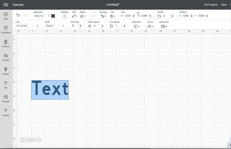
To start, I opened Cricut Design Space and created a new project page. I clicked the text box button in the left menu to bring up a new text box.
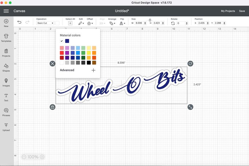
Once I typed in my text, “Wheel O Bits”, I then selected the font from the drop down menu. I switched the selection filters to only include fonts on my computer and not all of the ones I would need to purchase from their website.
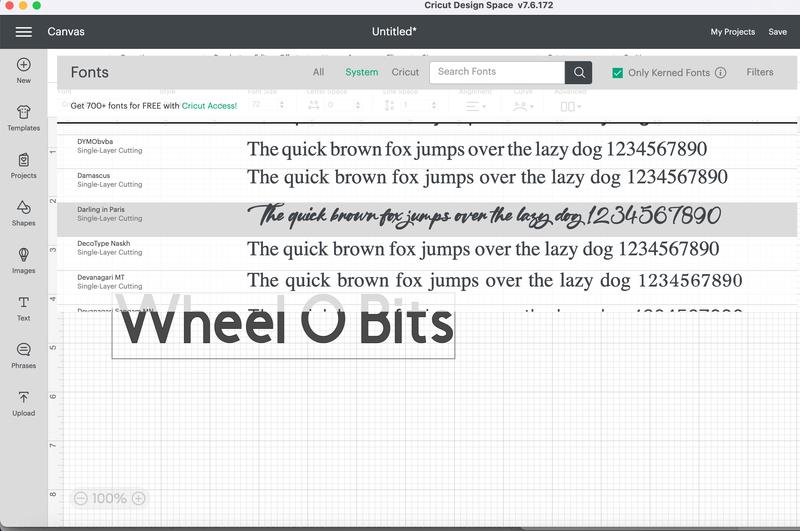
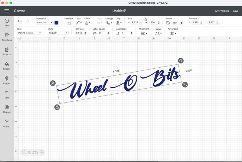
I really liked how this font swept across the page! Next, I rotated the design so it wouldn’t just be flat across our machine. I also changed the color of the font to navy, one of our school’s primary logo colors.
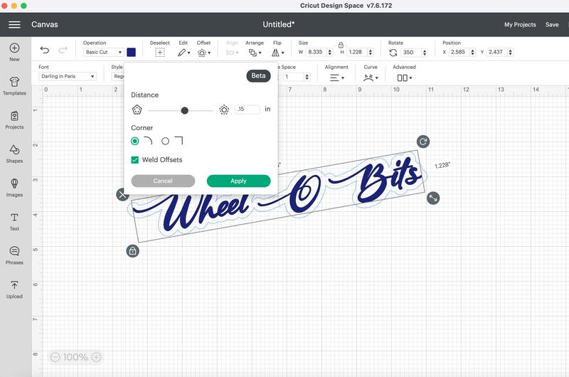
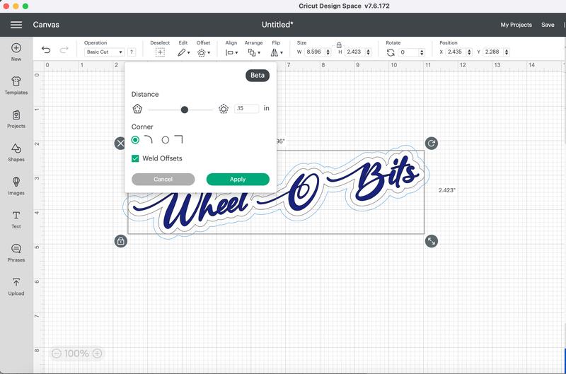
The next part is a new addition to the Cricut software. I was able to select the “offset” tool to create an outline (or offset) of the font once I selected it. You can change the thickness of the offset, as well as decide if you want it to have rounded corners or straight ones. I chose rounded and set my offset to .15” around the entirety of the text box.
I then selected just the offset and changed the color to white.
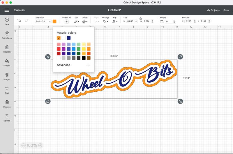
Next, to set the outer outline, there are two options. You can either select just the text and enlarge the offset in the back to one greater than the offset in layer one. Or, what I chose to do was to select the entire image on the page (the text box along with the first offset) and create a second offset of the same width from this one at .15”.
Finally, I changed the offset color of the second offset. I played around with a few color options before settling on the orange background. Even though it is not one of our main school colors, it is used in our branding files so I decided the pop of color would look great! We can, of course, change this when we actually go to cut the vinyl by just placing the color vinyl we want to use on the mat.
Once the design was created, I simply needed to hit the “Make It” button in the top right corner. Because I set up each layer with a different color, the design software recognized that and put each one on it’s own mat ready for cutting.
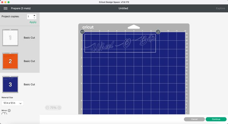
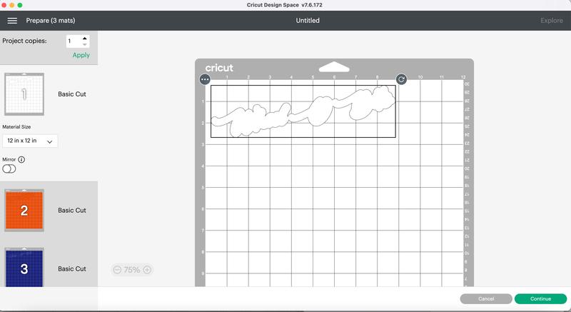
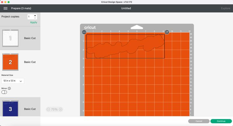
This way, I only had to load the needed color onto the mat, press load and hit cut. When the first one was completed, it notified me to place the second and then third run until we were complete.
After everything was cut, I layered the stickers and we are all set!
PLACE FINAL STICKER HERE!!!
Front Door and iPad Holder
Barbara Morrow and I also worked on designing and creating the front door and the ipad holder. We measured (and remeasured) and designed the files in Corel Draw. To see the details of this part of the project, please visit our group site.
We were thrilled with the way it all turned it!
Additional Work
Barbara Morrow designed the small boxes for holding the bits. I worked with Barbara to get them printed on the 3D printers. When Barbara designed them, the orignal lids for the boxes did not work, as when she placed a bit into it, it would crack. This was a design issue with printing them on the 3D printers, as the nature of this type of print would cause them to break at the “level” of the print where they make contact with the base. We confirmed this in our discssion with Dr. Fagan later that day.
Barbara and I discussed printing a test cap on the SLA printer to see if we would have the same issue. We opted to use the slightly flexible “durable” resin for this part. We used the resin printers in week 6 of Fab Academy and it lists all of the details on how to use these printers.
Once our test lid was washed and cured, Barbara added a bit and it worked! I quickly set up a file to print 30 more of the lids (a few extras just in case we needed them), and we continued working on other parts of our project. We came in the next day and Barbara continued to wash and cure the lids and had them ready to go by the time I got back to the lab!
To view my contributions on our group page, along with my colleagues, please visit here.