Week 13: Input Devices
Goals for Input Devices
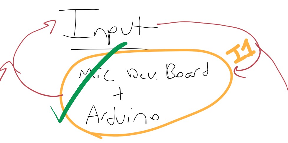
- Create an MCU board incorporating both input/output devices that is a spiral towards final project (Int1)
- ~ Use ATTINY ADC and DAC bare metal commands (replacing Arduino commands)~
- Begin experimenting with computer interfaced oscilloscope
~ are stretch goals ~
Simplest Possible Hello Mic.
Would’ve been too easy…
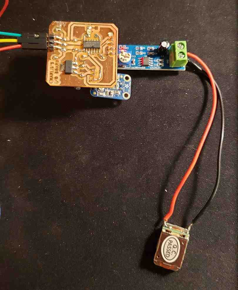
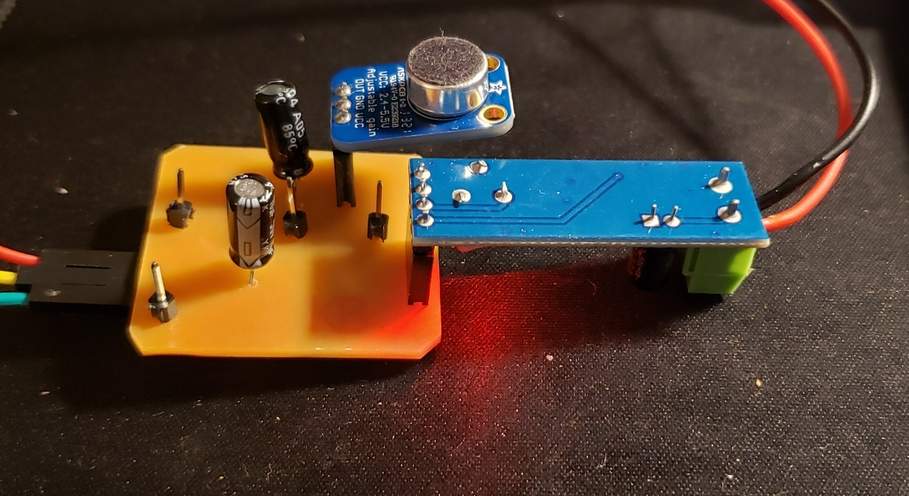
I started by taking the output setup I’m calling O1, and simply unplugging the 3.5 mm input, and plugging in the max 4466 Electret dev. board we had purchased. I then basically had the BD transducer + pre-amp dev. board + electret dev. board. If this worked, I would essentially be skipping straight to Int1 on the spiral chart. However, when I plugged it in, I received an unintelligible signal. It made sound when I spoke into it, but it was high pitch, unintelligible, and unpleasant. I quickly broke down the setup out of fear of blowing the mic or blowing the Transducer. And then I noticed this bit of language on the website.
The output pin is not designed to drive speakers or anything but the smallest in-ear headphones - you’ll need an audio amplifier (such as our 3.7W stereo amp) if you want to connect the amp directly to speakers. If you’re connecting to a microcontroller pin, you don’t need an amplifier or decoupling capacitor - connect the OUT pin directly to the microcontroller ADC pin.
Looks like I will either need to use a class D amplifier or go straight to digital using an ADC pin on a MCU.
Following microphone tutorials (I1)
Following this tutorial here, I was able to duplicate the simplest possible circuit proving that the Max4486 microphone dev. board is able to output data. Here is the microphone output of my voice plotted on the serial plotter.
Following a 2nd tutorial, I then tried registering the microphone using bare metal ADC commands and circumventing the analogRead function. Here are the results.
This seems to fufill the bare minimum for step I1 on my spiral development map.
Hello Microphone with AT TINY 412 (I2) 1st Attempt
Following along my spiral development map, I attempted to make the simplest possible circuit to receive mic input but using the 412 instead of Arduino. I began by digging through the 412 datasheet to understand and implement the ADC. In concept, this was very similar to the code I had implemented as a part of my I1 circuit, which used the arduino’s ADC to process the incoming soundwave. In practice, I had to comb through the datasheet to understand all the different registry options and implementation practices. I arrived at something that seemed like something with the following code.
void setup() {
  //Configuring LED for Arduino pin 1
  pinMode(1, OUTPUT);

  // configure software serial
  //SoftwareSerial Serial(RX, TX);
  //Serial.begin(9600);

  // Configuring ADC
    // select 10-bit resolution as opposed to 8-bit (1)
    ADC0.CTRLA |= 2; // 2 = 010. // 2nd bit enables freerunning mode for continuous measurement

    //Selects Vin as voltage reference and configure prescaler to highest possible resolution. CLK_PER divided by 2
    ADC0.CTRLC |= 7; //  000 is for min. prescaler of 2. or 23 = 010111, 111 is for max. prescaler of 256

    //select input pin for ADC to pin 6 (arduino pin 0). 110 is binary of 0x06.
    ADC0.MUXPOS |= 0x06;

    // enable ADC via first bit
    ADC0.CTRLA |= (1 << 0);

}

void loop() {
  // put your main code here, to run repeatedly:

  //Start a freerun measuring
  ADC0.COMMAND |= (1 << 0);

  incomingAudio = ADC0.RES; // verified with an LED that this is somehow always 255 or less, despite being set up for 10-bit readings

    if (incomingAudio >= 255){ // clipping indicator
        digitalWrite(1, HIGH);
        delay(30);
  }
    else{
        digitalWrite(1, LOW);
  }
}
Now the primary headwind I am finding in programming the 412 is that I no longer have access to serial communication. As such, it makes it difficult to debug or even see my readings I am getting with the microphone. So with the above code I was able to successfully have an LED that brightens in response to my voice. Though the LED is blinking Just a lot of static from the speaker and then even more static when I talk into the mic. I also tested the output value using an LED, which is of course limited in scope. That is when I discovered the output value is always less than or equal to 255, which is surprising because the output is set to 10-bit (0-1055). Something isn’t working quite right, and I need a better debugging method than an LED.
Here are the results of this first attempt.
As you can see, this example is less than satisfactory.
Gaining Access to Serial communication on 412
Adam helped me gain access to Serial communication with the 412 board. This comprised of two main steps.
- Incorporating a special line of code
- Modifying an Arduino to pass-through the RX/TX communication
Incorporating a special line of code
Per the documentation on megatinycore here,
This matches the megaTinyCore 412/402 Rev. - and Rev. A breakout boards below.. On bootloader . In 2.0.0 and later, this is no longer the case! You must call Serial.swap(1) prior to Serial.begin() to move it to the alt pins (or connect your adapter to pins 0 and 1 instead of 2 and 3). It should never have been done that way in the first place. Rev. B of the breakout boards that has the FTDI header tied to the standard serial pins is now available.
I would like to reserve pin 0 (PA6) for DAC output. Therefore, I cannot use pin 0 for RX/TX. Therefore, I call “Serial.swap(1)” before “Serial.begin()”.
Modifying an Arduino to pass-through the RX/TX communication
Adam noted that the Arduino is not setup to pass through serial communcation by default. To do this, I actually needed to remove the 328 chip from the Arduino. My understanding is that when you do this, the smaller ATMEGA16U chip takes over. This chip is able to pass through the RX/TX.
With these two changes, I am able to hook up RX/TX in the following ways.
- Pin 2 (PA1) as TX <-> Arduino D1 (TX)
- Pin 3 (PA2) as RX <-> Arduino D0 (RX)
note: normally the TX on a transmitting board might connect to the RX of a receiving board, and vise versa. In this case, Adam said to connect TX to TX and RX to RX since the arduino is simply passing the data through.
The main difficulty with this setup is that I must use the SAMD chip to program the 412 and the modified arduino unit to power/communicate it. So the workflow involves a lot of plugging/unplugging.
Hello Microphone with AT TINY 412 (I2) 2nd Attempt
Now that I have serial communication setup with the 412 board, I continued to work on my hello microphone example from above without much success. I then decided to step back to a simpler example, and stop using bare metal commands for now. Therefore, I went back to my code for I1 and simply adapted it for use with the 412.
const int sampleWindow = 50; // Sample window width in mS (50 mS = 20Hz)
unsigned int sample;

void setup()
{
   // configure serial
   Serial.swap(1); // makes pin 2 TX and pin 3 RX (arduino pin #'s)
   Serial.begin(9600);
}

void loop()
{
   unsigned long startMillis= millis();  // Start of sample window
   unsigned int peakToPeak = 0;   // peak-to-peak level

   unsigned int signalMax = 0;
   unsigned int signalMin = 1024;

   // collect data for 50 mS
   while (millis() - startMillis < sampleWindow)
   {
      sample = analogRead(1);
      if (sample < 1024)  // toss out spurious readings
      {
         if (sample > signalMax)
         {
            signalMax = sample;  // save just the max levels
         }
         else if (sample < signalMin)
         {
            signalMin = sample;  // save just the min levels
         }
      }
   }
   peakToPeak = signalMax - signalMin;  // max - min = peak-peak amplitude
   double volts = (peakToPeak * 5.0) / 1024;  // convert to volts
   Serial.print(0); // To freeze the lower limit
   Serial.print(" ");
   Serial.print(6); // To freeze the upper limit
   Serial.print(" ");
   Serial.println(volts);
}
So after this success, it begs the question, why the bare metal commands for the ADC are not playing nicely? Perhaps the sample window code and peak-to-peak commands are important to offering useful output. Perhaps the issue has less to do with the ADC and more to do with the structure of the program.
This MVP “Hello Microphone example” was later duplicated on an AVR 1614, using arduino pin 3 instead of 1.
MVP Hello Speaker (Int1)
Then, I turned my attention to creating an MVP Microphone+speaker combo. To do this, I would combine my MVP Hello Mic example that uses AnalogRead() for input with the intro to DAC example code provided from AVR for output. An important change I made on the input side was to change the sampleWindow from 50 ms to 500 uS. To do this properly, I had to change the code millis() to micros() and also change the variable startMillis to be startMicros. The 50 mS sampleWindow correlates with a 20 hz sample frequency, which is far too low to collect a useful noise signal. The 1000 uS correlates with 1000 hz. I have read in multiple places that as a rule of thumb, you want the sample frequency to be at least double your highest frequency sound waves that we are trying to detect. I have also read that dental drill sounds occur at the 2000 and 6000 hz, so in the long run I will need to increase the sample rate even further. Even at this rate, I detected that the code was taking 32 individual measurements within the 1000 uS sample window, so there is definitely room to shorten the sample window. That said, the code seemed to start having errors when I tried shortening to 100 uS. Specifically, the readings PeakToPeak readings were reading at only 0 or 68000. This error is currently inexplicable, but resolved when I increased the sample window, so I will stick with 1000 uS for now.
So here is the code,
/****************************************
This code attempts to create INT1 by combining Hello_Mic_412 and AVR intro to DAC
-
****************************************/
#include <avr/io.h>
#include <util/delay.h>

/* VREF Startup time */
#define VREF_STARTUP_MICROS (25)

unsigned long startMicros;
unsigned int peakToPeak;   // peak-to-peak level
unsigned int signalMax;
unsigned int signalMin;
unsigned int signalCutoffMin;
unsigned int signalCutoffMax;
unsigned int counter1 = 0;
double volts;
unsigned long sampleWindow = 1000; // Sample window width in uS (100 uS = 10000Hz)
unsigned long sample;

//Defining functions
void VREF_init(void);
void DAC0_init(void);
void DAC0_setVal(uint8_t val);

void setup()
{
   // configure serial
   Serial.swap(1); // on 412, makes pin 2 TX and pin 3 RX (arduino pin #'s)
   Serial.begin(9600);

  // Configure VREF and DAC
   VREF_init();
   DAC0_init();
}

void VREF_init(void)
{
   /* Voltage reference at 4.34V */
   VREF.CTRLA |= VREF_DAC0REFSEL_4V34_gc;
   /* DAC0/AC0 reference enable: enabled */
   VREF.CTRLB |= VREF_DAC0REFEN_bm;
   /* Wait VREF start-up time */
   _delay_us(VREF_STARTUP_MICROS);
 }

void DAC0_init(void)
{
 /* Disable digital input buffer */
   PORTA.PIN6CTRL &= ~PORT_ISC_gm;
   PORTA.PIN6CTRL |= PORT_ISC_INPUT_DISABLE_gc;

   /* Disable pull-up resistor */
   PORTA.PIN6CTRL &= ~PORT_PULLUPEN_bm;

   /* Enable DAC, Output Buffer, Run in Standby */
   DAC0.CTRLA = DAC_ENABLE_bm | DAC_OUTEN_bm | DAC_RUNSTDBY_bm;
}

void DAC0_setVal(uint8_t val)
{
  DAC0.DATA = (val*256)/1024 - 1;
}

void loop()
{
   startMicros= micros();  // Start of sample window
   peakToPeak = 0;   // peak-to-peak level

   signalMax = 0;
   signalMin = 1024;
   signalCutoffMin = 30; // on 10-bit scale
   signalCutoffMax = 100;
   counter1 = 0;

   // collect data for 100 uS
   while (micros() - startMicros < sampleWindow)
   {
      sample = analogRead(1);
      if (sample < 1024)  // toss out spurious readings
      {
         if (sample > signalMax)
         {
            signalMax = sample;  // save just the max levels
         }
         else if (sample < signalMin)
         {
            signalMin = sample;  // save just the min levels
         }
      }
    counter1++; //At 100 uS (10000 HZ) sample window, makes it through this loop 3-4 times. At 1000 uS (1000 HZ) sample window, makes it through this loop 33 times. Note these results are while using serial println, which may slow down the processing.
   }
   peakToPeak = signalMax - signalMin; // max - min = peak-peak amplitude

   //Cutout signal noise
   if(peakToPeak < signalCutoffMin) {
      peakToPeak = 0;
   }
   /*if(peakToPeak > signalCutoffMax) {
      peakToPeak = 100;
   } */

   //volts = (peakToPeak * 5.0) / 1024;  // convert to volts
   //peakToPeak = map(peakToPeak, 0, 1023, 0, 255); // Convert 10-bit input to 8-bit output
   DAC0_setVal(peakToPeak);
   //Serial.print(0); // To freeze the lower limit
   //Serial.print(" ");
   //Serial.print(6); // To freeze the upper limit
   //Serial.println(counter1);
   Serial.println(peakToPeak);
}
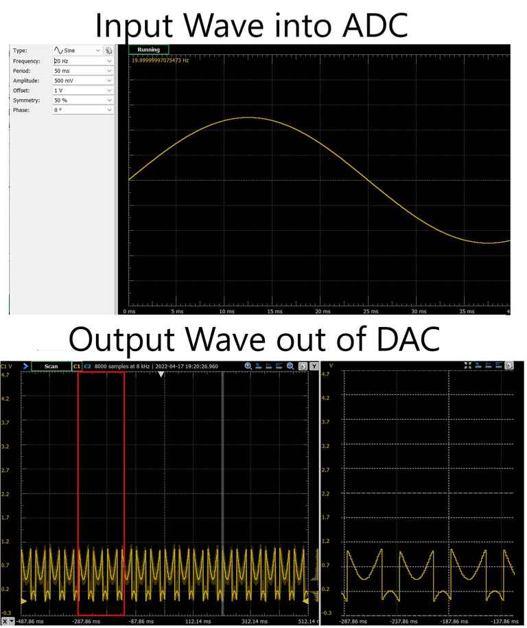
And here are are the current results.
I have a few theories about why this signal is unintelligible.
- The sample frequency is not fast enough to sample get an accurate picture of the input wave.
- The code is producing something other than a sound signal. (In hindsight this was correct)
- Something is wrong with the DAC in that its losing data.
I will now attempt to diagnose the issue using our labs analog discovery systems kit, which can read/write both analog/digital signals. This kit turned out to be a game-changer.
The next day, I realized that I should vastly simplify the code. Instead of trying to take the PeakToPeak voltages, cutoff voltages, and sample windows, I am trying to create the simplest code possible. Here is this new code,
/****************************************
This code attempts to create INT1 by combining Hello_Mic_412 and AVR intro to DAC
-
****************************************/
#include <avr/io.h>
#include <util/delay.h>
#include "Arduino.h"

/* VREF Startup time */
#define VREF_STARTUP_MICROS (25)

unsigned long sample;

//Defining functions
void VREF_init(void);
void DAC0_init(void);
void DAC0_setVal(uint16_t val);

void setup()
{
   // configure serial
   //Serial.swap(1); // on 412, makes pin 2 TX and pin 3 RX (arduino pin #'s)
   //Serial.begin(9600);

  // Configure VREF and DAC
   VREF_init();
   DAC0_init();

   /* Voltage reference at 4.34V for AnalogRead() */
   analogReference(INTERNAL4V3);

   // Setting Arduino pin 1 (PA5) up as input pin
   pinMode(1, INPUT);

}

void VREF_init(void)
{
   /* Voltage reference at 4.34V for DAC*/
   VREF.CTRLA |= VREF_DAC0REFSEL_4V34_gc;

   /* DAC0/AC0 reference enable: enabled */
   VREF.CTRLB |= VREF_DAC0REFEN_bm;
   /* Wait VREF start-up time */
   _delay_us(VREF_STARTUP_MICROS);
 }

void DAC0_init(void)
{
 /* Disable digital input buffer */
   PORTA.PIN6CTRL &= ~PORT_ISC_gm;
   PORTA.PIN6CTRL |= PORT_ISC_INPUT_DISABLE_gc;

   /* Disable pull-up resistor */
   PORTA.PIN6CTRL &= ~PORT_PULLUPEN_bm;

   /* Enable DAC, Output Buffer, Run in Standby */
   DAC0.CTRLA = DAC_ENABLE_bm | DAC_OUTEN_bm | DAC_RUNSTDBY_bm;
}

void DAC0_setVal(uint16_t val)
{
  DAC0.DATA = ((val*256)/1024)- 1; // converting from 10-bit input (ADC) to 8-bit output (DAC)
}

void loop()
{
   sample = analogRead(1);
   DAC0_setVal(sample);

}
And here are the results,
And now, I am getting very similar results using the ADC directly as opposed to ardunio functions like analogRead(). Here is my bare metal code,
/* 3.33 MHz (needed for delay) */
 #define F_CPU (3333333UL)

 /* VREF Startup time */
 #define VREF_STARTUP_MICROS (25)

 #include <avr/io.h>
 #include <util/delay.h>
 #include "Arduino.h"

 //defining functions
 void VREF_init(void);
 void DAC0_init(void);
 void ADC0_init(void);
 uint16_t ADC0_read(void);
 void DAC0_setVal(uint8_t val);

 void VREF_init(void)
 {
   /* Voltage reference at 4.34V */
   VREF.CTRLA |= VREF_DAC0REFSEL_4V34_gc;
   /* DAC0/AC0 reference enable: enabled */
   VREF.CTRLB |= VREF_DAC0REFEN_bm;
   /* Voltage reference at 4.34V */
   VREF.CTRLA |= VREF_ADC0REFSEL_4V34_gc;
   /* ADC0 reference enable: enabled */
   VREF.CTRLB |= VREF_ADC0REFEN_bm;
   /* Wait VREF start-up time */
   _delay_us(VREF_STARTUP_MICROS);
 }

 void DAC0_init(void)
 {
 /* Disable digital input buffer */
   PORTA.PIN6CTRL &= ~PORT_ISC_gm;
   PORTA.PIN6CTRL |= PORT_ISC_INPUT_DISABLE_gc;

   /* Disable pull-up resistor */
   PORTA.PIN6CTRL &= ~PORT_PULLUPEN_bm;

   /* Enable DAC, Output Buffer, Run in Standby */
   DAC0.CTRLA = DAC_ENABLE_bm | DAC_OUTEN_bm | DAC_RUNSTDBY_bm;
 }

 void ADC0_init(void)
 {
   ADC0.CTRLC |= ADC_PRESC_DIV256_gc /* CLK_PER divided by 4 */
   | ADC_REFSEL_VDDREF_gc /* VDD reference */
   | ADC_SAMPCAP_bm; /* Sample Capacitance Selection:
  enabled */
   ADC0.CTRLA = ADC_ENABLE_bm /* ADC Enable: enabled */
   | ADC_RESSEL_10BIT_gc; /* 10-bit mode */
   /* Select ADC channel */
   ADC0.MUXPOS = ADC_MUXPOS_AIN5_gc; //connects PA5 as the input pin for the ADC.
 }

 uint16_t ADC0_read(void)
 {
   /* Start ADC conversion */
   ADC0.COMMAND = ADC_STCONV_bm;
   /* Wait until ADC conversion done */
   while ( !(ADC0.INTFLAGS & ADC_RESRDY_bm) )
   {
   ;
   }
   /* Clear the interrupt flag by writing 1: */
   ADC0.INTFLAGS = ADC_RESRDY_bm;
   return ADC0.RES;
 }

 void DAC0_setVal(uint16_t val)
 {
   DAC0.DATA = val*255/1023; //10-bit ADC Val becomes 8-bit DACval
 }

 int main(void)
 {
   uint16_t adcVal = 0;
   VREF_init();
   DAC0_init();
   ADC0_init();
   /* Wait VREF start-up time */
   _delay_us(VREF_STARTUP_MICROS);

   while (1)
   {
     adcVal = ADC0_read();
     /* do something with the adcVal */
     DAC0_setVal(adcVal);
   }
 }
And here is the result.
After working with Adam Harris and attempting to debug the issue, we realized the issue was related to my method of conversion. The reason for a conversion in the first place is because the ADC outputs a 10-bit value and the DAC requires an 8-bit value as input. My original code looked like this,
 void DAC0_setVal(uint16_t val)
 {
   DAC0.DATA = (val*256)/1024 //10-bit ADC Val becomes 8-bit DACval
 }
After Adam recommended bit shifting (for the fastest possible conversion), my code looked like this.
 void DAC0_setVal(uint16_t val)
 {
   DAC0.DATA = (val >> 2); //10-bit ADC Val becomes 8-bit DACval
 }
The latter code simply shifts all binary digits two places to the right and drops off the two “least significant bits”. This worked and resolved the issue! Here was my clean sine wave as a result.
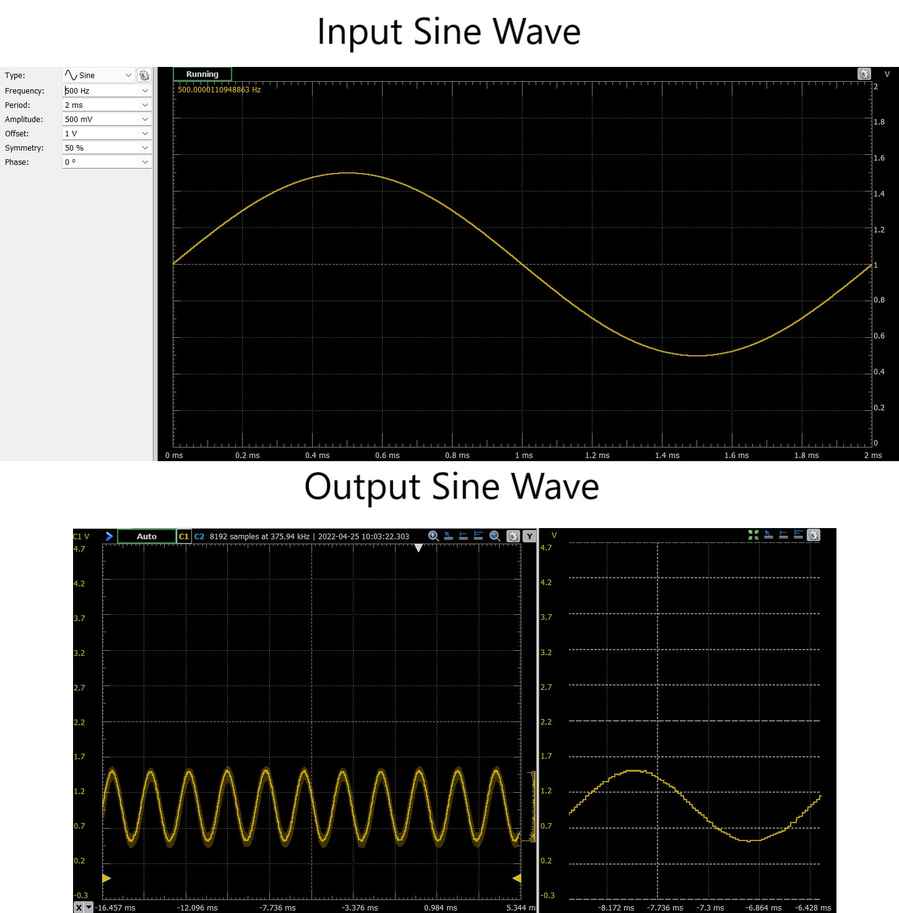
To generate a smoother wave, I took the chance to change the prescalar down from 256 to 32. However, despite my first guess, sending the prescalar to the lowest possible value of 2 did not result in the smoothest wave. For some reason I found a happy balance at 4. Perhaps the program is unable to run so fast and the lower prescalar is causing issues. Even still,
From here, it seems that the only issue pertained to amplitude of the wave. The offset I was inputting into the Wave generator was outputting nicely, but the output wave had a shorter amplitude than the input wave. I figured this had something to do with the reference voltages. Still this was puzzling because I had clearly set both the ADC and the DAC to a reference voltage of 4.3V.
   /* Voltage reference at 4.34V */
   VREF.CTRLA |= VREF_DAC0REFSEL_4V34_gc;
   /* Voltage reference at 4.34V */
   VREF.CTRLA |= VREF_ADC0REFSEL_4V34_gc;
   /* ADC0 reference enable: enabled */
However, upon further parsing the code, it seems I made a change to the ADC reference voltage elsewhere
ADC0.CTRLC |= ADC_REFSEL_VDDREF_gc ; /* VDD reference */
Looking in the datasheet, this line of code asks the ADC to use VDD (~5V) as the reference voltage. Upon commenting this line, the issue resolved and the input/output waves were no longer different scales.
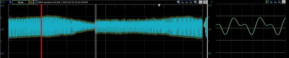
Now that I was getting satisfactory results with the waveform generator and scope, it was time to once again try the mic/speaker setup. For better insight, I left the scope connected and only disconnected the waveform generator. These results looked very promising! Especially considering I could finally hear myself through the mic and the words began to sound somewhat intelligible…
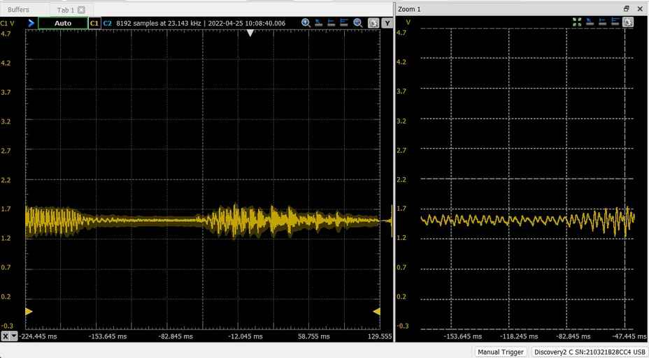
Its worth noting that while these results look good on the scope, the speaker is still struggling to produce intelligible output. This may be where more efficient code will come in. Either that, or something is wrong with how I am driving the speaker. In any event, these are likely changes that can be made in code.
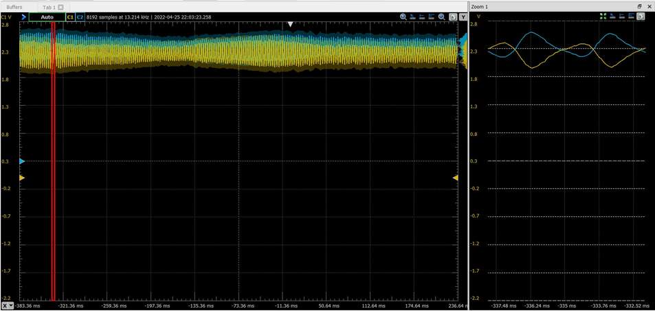
As an experiment, I connected 2 oscilloscope probes (C1 & C2) to the Mic output and DAC output respectively. Much to my suprise, the waves were very much in lockstep.
This can be seen even better with by applying a Voltage offset to the DAC output (C1).
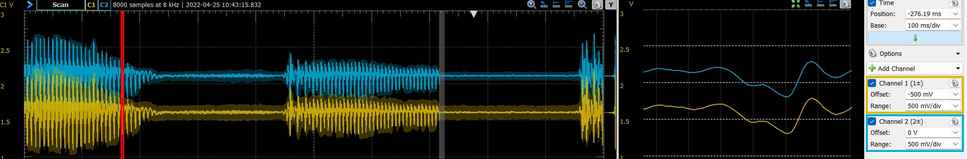
So how about inverting the wave? I figured this might most easily be done by simply inverting the binary value before outputting it out of the DAC. This can be easily done with a ~ sound, so my new code becomes,
void DAC0_setVal(uint16_t val)
{
   DAC0.DATA = ~(val >> 2); //10-bit ADC Val becomes 8-bit DACval and ~ inverts the wave
}
This code worked almost entirely as expected. The only caveat was that a voltage offset of -1.05 V was now needed to once again line the waves up, which will of course be necessary when it comes to canceling them. This voltage offset could have to do with the different input voltages (5V vs. 3.3V), ADC/DAC reference voltages (unlikely because they’re both set at 4.3V currently), or the 10-bit to 8-bit conversion. After talking to Adam Durrett, we determined that this 1.05 V offset is due to the differential between the refence voltage (4.34 V) and the mic VDD, 3.3V.
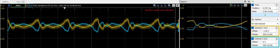
This is a huge leap forward for my progress towards my final project. While this is just a comparison of the mic output voltage vs. the DAC output voltage and isn’t exactly “Active Noise Cancellation”, these are very promising results that can tell us a few things. For one thing, the phase lag between the input and output seems to be tiny if not a non-factor. So small that I am unable to take an accurate measurement. Even still, it is fair to say it is on the order of nanoseconds, which I anticipate will be a non-factor. The DAC output is noticeably noisier than the mic output, but looks acceptable. We’re I to sum these two voltage signals together, I could easily produce a Voltage signal near 0 V (plus noise). However, in practice, I need to produce such an effect in 3D space with sound waves rather than voltage outputs on a board. That will be the trick.
I/O Board Design and Production
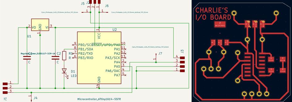
Figuring that any further changes can be made after the fact, I figured it was time to finally mill a board for input/output devices week. Here is what I came up with in KiCad following the process learned during week 6, documented here.
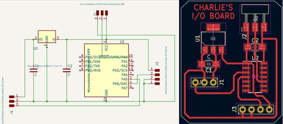
After this pic was taken, an LED/resistor was added to PB1 (physical pin 8). Additionally, 4 single header pins were scattered around the board so that we can continue to probe VDD, ground, Mic Output, and the DAC Output. Also, the SMD capacitors were changed to through-hole, after I realized I would need polarized capacitors. Here is the final design before production. For the production process, I followed the workflow I learned during week 4, documented here.
Here you can see the milled and stuffed board in action.
I had drawn through holes to connect the breakout boards, and had planned to solder in Feather-pin (female) headers so these pieces could be swapped in/out. However, at the last minute I realized that I would be unable to solder them to the top-side. This is when I realized a large drawback of FR-1 (one-sided) Copper boards. As far as I can tell, I can only solder through-hole components in from the one side. So in the case of soldering headers, I was forced to have them pointing out of the bottom-side of the board. Luckily, the orientation worked out so that the components could point the same direction. Additionally, the through-hole capacitors and probe headers were soldered in the same manner as to stick out of the bottom. While this worked, this seemed to make for a very fragile design that could easily rip a trace from the top-side of the board.
With my first attempt at programming the board, I ran into the following error.
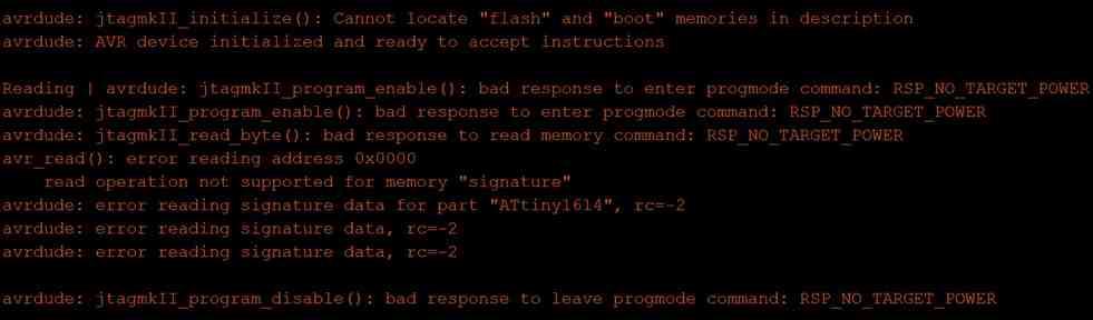
I had the gut feeling that this was a soldering issue. The power/ground connections looked fine. However, in my haste I had decided not to solder many of the pins of the 1614, since they appeared unused. At this point, I realized that one of these supposedly unused pins, was the UPDI connection on pin 10 (PA0), which was connected underneath the chip. A drop of solder on this pin and suddenly the board programmed correctly. This experience has led me to add to my list of “takeaways” below.
Here is the proof of the pudding. The two scope channels looking at mic output and inverted. DAC output of this new board.
The only complaint I have right now with this new setup is that the speaker output is still less intelligible than desired. This could have to do with the voltage I am attempting to drive at, or any number of things. Upon proofreading my documentation this week, I noticed a quote near the top of this page from the Transducer’s datasheet that claimed the transducer does not need an amplifier if connected directly to the ADC out pin. So I attempted to remove the amplifier. However, in my case, the speaker is plugged directly into the DAC out pin. This did not work. I did not get an audible signal out of the transducer without the amplifier in play.
Perhaps next, I will try lowering the DAC reference voltage and amplifying it with the amplifier.
…
Since this last remaining issue pertains more to the speaker Output, I will continue documenting it on my Outputs page found here.
Link to Group work
For this week, our group decided to anaylze my circuit setup for the group project. Documentation of this can be found here.
- K.I.S.S. My inclination that I would eventually need BM commands was correct, but I jumped too quickly into it before I even had an MVP working spiral.
- My decision to create a breakout board for the 1614 was a good one. Breadboard first.
- Serial communication is too slow for many applications including audio.
- Plugging in power/ground wrong can potentially fry a chip.
- Copying/pasting code is dangerous!! Copy line by line and always know what each line is doing.
- Math is much slower than switching bits. E.g. Rather than dividing by 4, converting 10-bit to 8-bit via bit shifting can happen in one clock-cycle.
- The analog-to-digital discovery kit is an etremely powerful kit and will be essential to the rest of my work on my final project.
- Through-hole components can only be soldered from one-side with FR-1. This also creates a very fragile board.
- Be careful hiding connections underneath components.
- When in doubt, solder all pins.
Note: All design files and images can be accessed in my git repository found here.
All works shared on this site 'A Fab Academy Journey with Charlie Horvath' by Charles W. Horvath are licensed under Attribution-NonCommercial-ShareAlike 4.0 International![]()
![]()
![]()
![]()