Week 10: Output Devices
Goals for Output Devices
- Create an MCU board incorporating both input/output devices that is a spiral towards final project (Int1)
- ~ Use ATTINY ADC and DAC bare metal commands (replacing arduino commands)~
- ~ Replace store bought audio amps with custom-built ones ~
~ are stretch goals ~
Simplest possible audio-out example (O1)
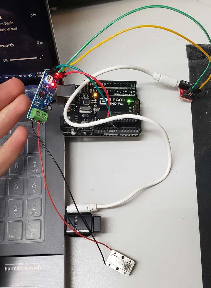
First I set about driving the BC transducer in any shape or way possible. Luckily, the lab had everything I needed aside from the transducer, which was ordered from Digikey.
BOM:
- Adafruit BC Transducer
- LM386 Audio Amplifier Dev. Board
- Sparkfun 3.5mm Jack Breakout Board
- Arduino for Power
- Aux cable for mono-audio
Everything was pretty straight forward since the dev. boards were nicely labled. I did take the chance to learn how a 3.5 mm jack actually works.
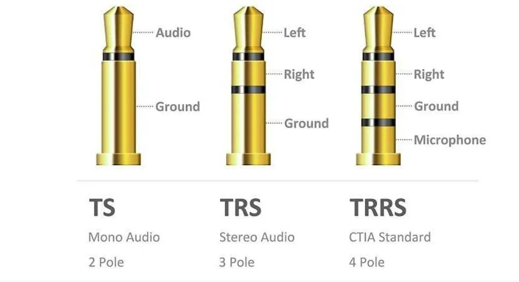
I am of course only working with mono sounds and would only need to use the pin connected to the “TIP” of the jack.
This neatly fufills step O1 on my spiral development roadmap:
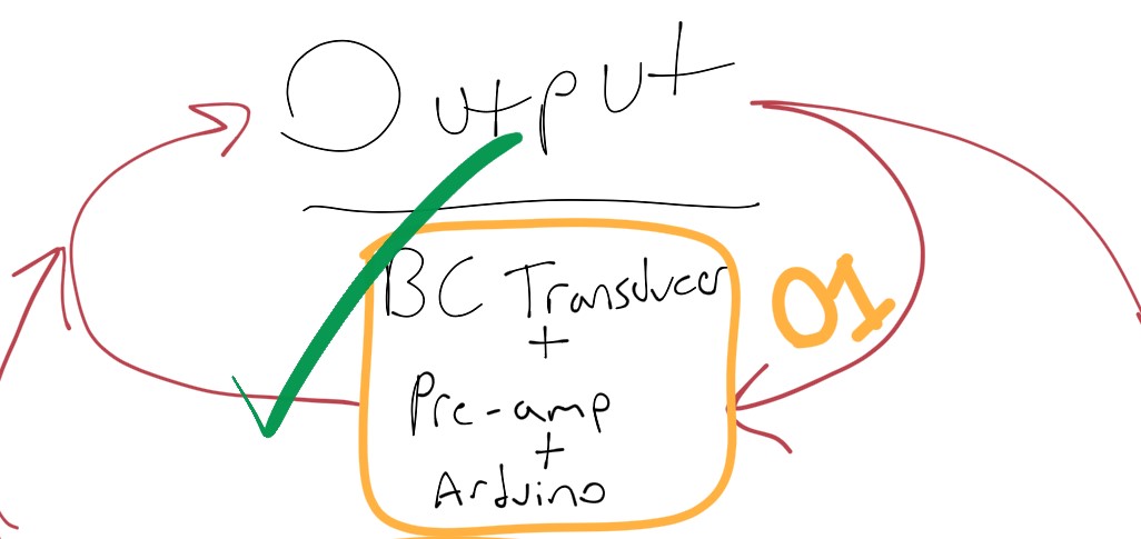
By using playing with this circuit, I have confirmed that the LM386 module will only run on 5V. This may be an issue for combining with the electret microphone Dev. board, which seems to only want to run well on 3.3V. However, after plugging in the two devices to their respective power supplies, I have found that each are reading correctly on a multimeter with respect to ground. Additionally, I’m reading a voltage differential of 1.7V when measuring between the two. It seems this will be a nonissue to drive the two devices at different voltages. Eventually, I will use a voltage regulator to supply the two different voltages within an integrated circuit.
Simple Tone example and Verification
I reproduced this simple Arduino tone example to produce different frequencies and note lengths through the transducer.
I combined this simple tone test with a guitar tuner that can read vibration. The thinking is that this could be a good way to verify that the BC transducer is tuned well and/or adjust the tuning to make sure that the output is transmitting as expected (on account of the unusual bone conducting nature of it). Here are the results.
It seems the speaker has nearly perfect pitch, so for now I will presume that no special considerations will need to be made on this front.
Replicating the AVR Examples
AVR has these great examples for getting started with the ADC and DAC peripherals. While I’ve had trouble with adapting the ADC example code for my needs, the DAC examples seemed to work out of the box for me. I was able to recreate the “Generating Constant Analog Signal Code Example” and “Generating Sine Wave Signal Code Example” on the 412, without changing any code. Better yet, since most ATTINY boards seem to have only one pin available for DAC output (PA6), I didn’t even need to change code when moving to the 1614 board. I suspect, the third example here “Reading DAC Internally With ADC Code Example” will be very relevant to my needs, once I can get the ADC code working. In hindsight, I actually needed to read the ADC internally to drive the DAC, rather than the other way around. For now, I will attempt to combine my Arduino code input with my DAC code output to generate my simplest possible combined board (Int1).
…
Since I combined inputs/outputs into one integrated circuits, the rest of this process and exploration are well documented on my inputs week page found here.
Debugging Speaker Output
This documentation jumps ahead to the end of inputs week, where I had completed building an integrated circuit board that incorporates both input and output devices. While the signals on the scope looked great, I was still having trouble driving a satisfactory sound from the microphone through the 1614 chip and out of the bone conducting transducer. This could have to do with the voltage I am attempting to drive at, or any number of things. Upon proofreading my documentation from inputs week, I noticed a quote near the top of this page from the Transducer’s datasheet, which claimed the transducer does not need an amplifier if connected directly to the ADC out pin. So I attempted to remove the amplifier. However, in my case, the speaker is plugged directly into the DAC out pin. This did not work. I did not get an audible signal out of the transducer without the amplifier in play.
Next I tried removing the microphone and instead utilizing aux input. Here was the exploration that followed.
This offered a rough but intelligible signal out of the transducer, coming from the mic input! This leads me to believe the issue has to do with the regulator giving me 4.2 V instead of the expected 3.3V. Interestingly, I tried 2 different regulators (ZLD 17-50 and RJK 17-5) and got the same results. Even looking at the RJK 17-5 datasheet, these results are surprising. I would expect a 5V Vin to offer 3.3V Vout. Whatever the case, I think I will be able to go back to the 3.3V LDO regulator we used for the SAM-D programmers during week 4. For the time being, I will continue to make use of the 3.3V power available on the arduino.
Output Amplifiers and final project
Replacing Amplifier Modules
My final project naturally built upon the work on this page. In both cases, I used a prebuilt LM386 amplifier module to power the transducer. That said, I aim to eventually move towards custom-made amplifier modules so that I can have more control over the output. I think these prebuilt modules are not built quite right and could be a large source of signal noise.
In fact, I’ve experimented with the building the minimum parts example listed in the LM386 Op-amp datasheet. Using only the parts we had on hand at the lab, I was forced to put multiple capacitors in parallel to achieve the desired capacitance. Note: it seems the large capacitance requires a polarized capacitor whereas the small capacitance requires a nonpolarized.
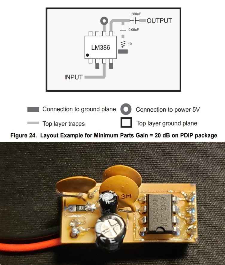
This amp is designed to be a drop-in modular replacement for the existing modules, which has obvious benefits. I’ve only briefly tested it but it seemed to work well. That said, as drawn, it is two quiet to be useful. Perhaps next, I will try to build the suggested 50x gain or 200x gain circuits listed in the datasheet.
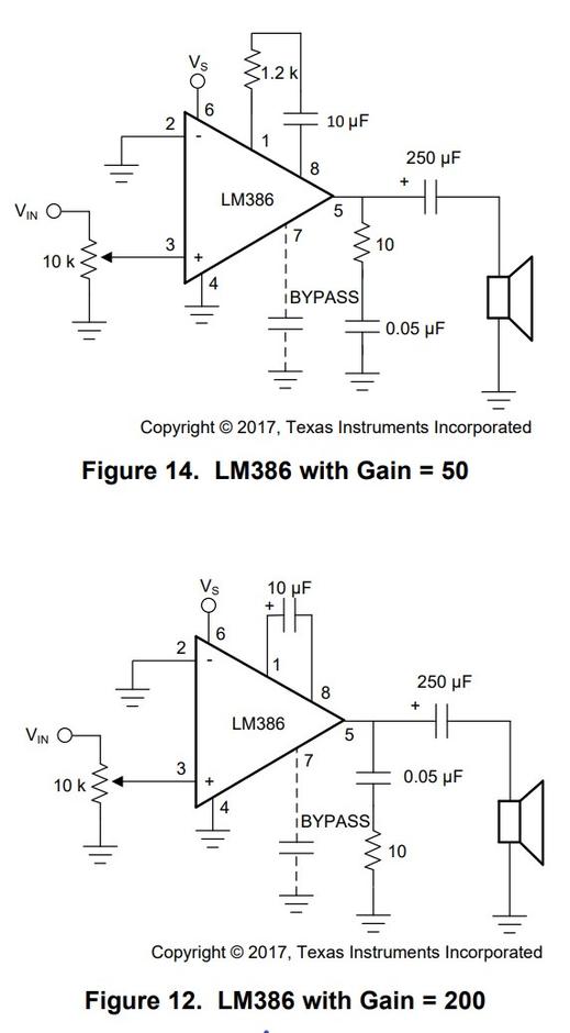
Next, I redesigned the circuit to be the 200x gain setup. Since the 20x was too quiet to be useful, the new plan is to make the output as loud as possible and attenuate the volume upstream, through digital means.
I built the 200x gain circuit pictured above. I left the bypass capacitor empty because the datasheet does not mention a value, it looks optional and I am unsure of the function. Additionally, the datasheet recommends a potentiometer to attenuate the incoming signal. Since I would like to attenuate the signal via digital means, I replaced this potentiometer with a static resistor. Since I will build 3 of these modules, I would like them to all have the same gain level which will be easier with a resistor in this position. That said, I tested a 0 Ohm, 5k Ohm, and 10k Ohm in this position. As expected, the 10k Ohm resistor offered the highest level of gain. Somewhat unexpectedly, the 10k also provided what seemed to be the least amount of signal noise. Perhaps this is because the volume of the input device, in this case an aux cable hooked into my computer, did not have to be at 100%. This is ideal for what I am trying to achieve so I ended up soldering 10k resistors on all 3 boards.
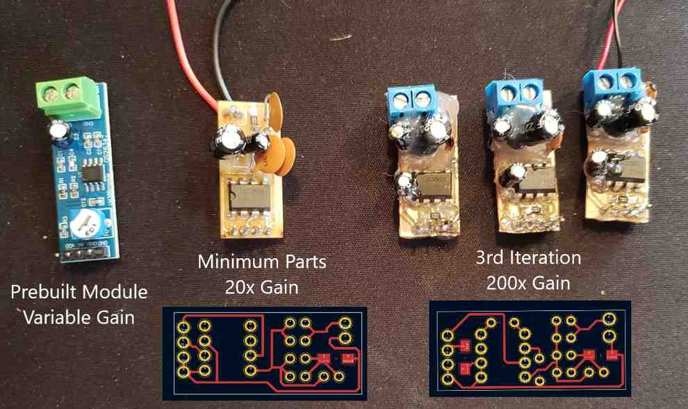
Design files for both the 20x and 200x modules can be found in my repo under week 10 files, here. You may notice that the 200x boards are caked in hot glue. I have learned overtime that through-hole components and single sided boards do not play nicely together. Specifically, traces rip quite often because of accidental forces applied to the components. Nidhie gave me the tip to add hot glue, which is seemingly electrically insulating and easily absorbs any forces applied to the components. This seems to work well. In the long run, I’d like to switch over to more surface mount components and double-sided boards for when through-hole is completely necessary. Ironically, these boards were actually milled on double-sided FR-1 because we ran out of single sided. I have found it quite easy to sand the copper off of the backside of the board after milling but before stuffing, to effectively create single-sided FR-1. Lastly, if I were to design these boards over again, I would design them so that the components would all stick out of the non-copper side. That way, all of the soldering happens on that side while all the hot glue on the underside. This would perhaps be easier to solder and resolder as needed.
These amplifiers all worked well driving them off of my computer. Next step will be to transfer them over to my final project in place of the existing prebuilt modules.
I began by replacing the amplifier in the known wand, since this was most accessible. By this point, I was feeling quite pleased with myself making these modules as drop-in replacements for the prebuilt modules, as opposed to designing them into the circuit boards themselves. This has modularity has offered me several advantages:
- Quicker feedback loop for prototyping the amplifiers
- Easier troubleshooting and the ability to revert to prebuilt modules
- Ability to swap boards and achieve a different gain (e.g. 50x -> 200x)
That said, I know that the way I’ve used the feather headers to make this connection is beyond just “bad practice” and in the territory of “janky”. Without the copious amounts of hotglue, traces would undoubtably rip. Whatever the case, here is the 200x module driving the mock-drill device for my final project.
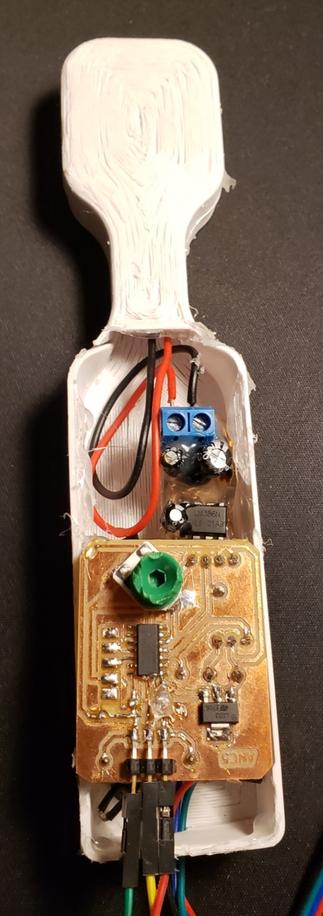
Through this device, the amplifier produced a clean sound at a great max volume. I am still working on getting the volume knob to work (I think its an issue with the code). Even still, the max volume is much better than with the 50x gain module, and the sound is arguably cleaner than with the prebuilt modules. So that said, I consider this exploration of amplifier modules to be a success. Design files for this amplifer and the mock-drill can be found in my git repository under final-files, here.
Time permitting, I will come back and test these amplifiers on the final project headphones themselves.
Link to Group work
This week our group decided to measure the power consumption of a DC voltage meter using a variable power supply. Documentation of this process can be found here.
- How an Aux chord works. Neat!
- Sound signals can be described entirely with a varying analog voltage.
- Any wave can be constructed using an infinite number of sine waves and deconstructed using a Fourier Transform.
- The BC transducer has perfect pitch.
- Digital processing of noise is powerful. Entire analog circuits can be replaced by small amounts of code. E.g. An inverting amplifier circuit, I included one character, a ~, to flip the bits and invert the wave.
- When mounting long through-hole components, utilize hot glue to avoid moment loads that can rip traces.
Note: All design files and images can be accessed in my git repository found here.
All works shared on this site 'A Fab Academy Journey with Charlie Horvath' by Charles W. Horvath are licensed under Attribution-NonCommercial-ShareAlike 4.0 International![]()
![]()
![]()
![]()