Week 11/12: Mechanical and Machine Design
For the full documentation of our group project, please visit our group site here
My contribution
For my part, I helped developed the concept/application for our team.
Additionally, I have worked with Scott to refine his design for the bit sleeve holder and A-frame which will hold the wheel.
For my main contribution, I took on the bulk of the design of the core ferris-wheel and connection to the motor.
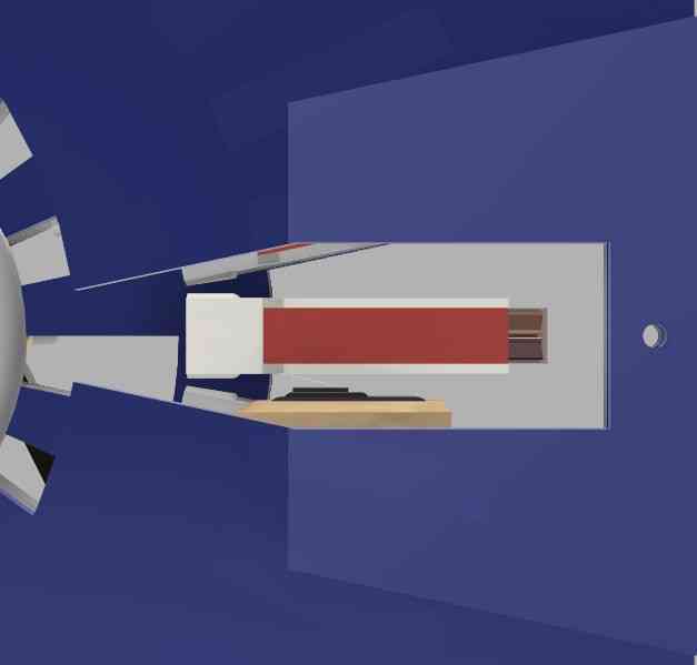
Additionally, I did my best to turn this design in Fusion 360 into a main assembly file. In some instances, this was as simple as bringing in other’s completed design files (bit holders, bit boxes) and in other instances this involved modeling the components others had made after the fact (e.g. Welded frame, wooden box frame). Here is the nearly complete CAD assembly that includes about 90%+ of the components. Notible exceptions are the electronics and the front door of the design, which includes the iPad holder. Time permitting, I will include these in the CAD assembly eventually since they are both important aspects of the design.
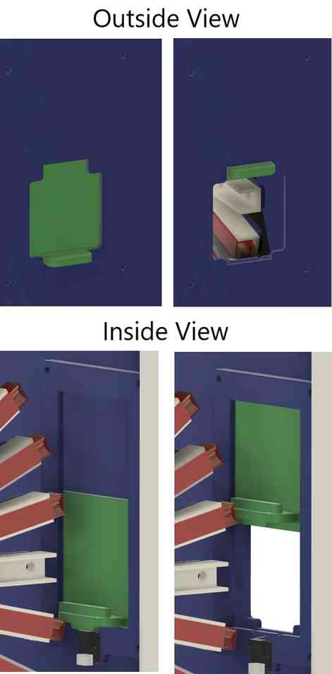
The other aspects that I took the lead on mechanical design include the acrylic side panels for the wooden frame Scott fabricated and the side door for bit retrieval. The latter was more complicated and took me some time to design correctly. I settled on a sliding door over a swinging door because this would allow me to position the limit switch in a hidden position, away from potential accidental finger presses. This is important since the current iteration of our code will begin to move the wheel to the home position when that switch is closed again (after bit retreival and closing of door). Here are some shots of the completed design.
The process of taking these photos made me realize there is an issue of clearance between the bit and the limit switch beneath the door.
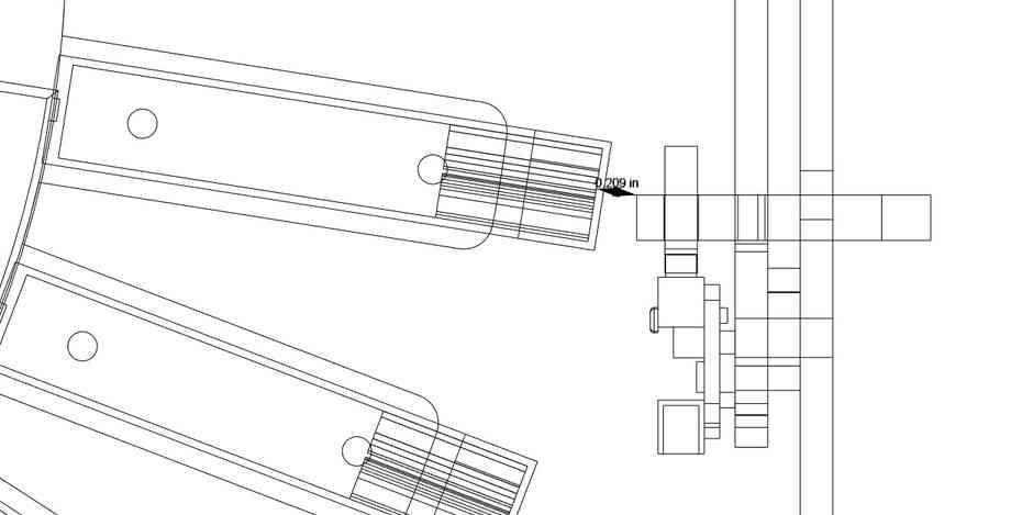
This prompted us to move the wheel about a 1/2” further away from the door to provide ample clearance. In practice, this caused two issues.
- The barcode was no longer front and center within the iPad’s focal range. This caused issues with the scanning of the bits.
- Less critical, the bit was now a bit too far deep in the box and difficult to reach.
As a result, we moved the wheel 1/4” back towards the side door to find a happy medium. This also prompted us to move the homing limit switch so that it would still be in range of the limit-switch-knocker Scott designed. Luckily, the 0.25” move of the wheel seemed to result in a major change of the camera’s ability to find the barcode. It seems that because the camera sees in a cone shape, a small movement of an object that is relatively far away from the camera, resulted in a big change for the location of the bit on the screen. The reaching distance for the bit was also now more acceptable, so this seems to be the wheel’s final resting place.
During the final assembly, a few things needed to happen on the fly. We had to position the limit switch for homing the wheel. This took some time to workout because we we’re running out of real-estate towards the front-right of the machine. This prompted a redesign of the home bit sleeve. Scott took on the task of redesigning and reprinting this piece. While Scott’s piece was printing, Nidhie and I focused on building out a stable base and arm for the limit switch to rest on. Luckily, Scott was able to send me the file so we were able to workshop ideas both physically as well as in CAD. This was really tricky and we went through several iterations before settling on the following design.
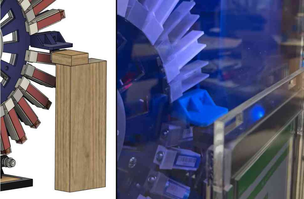
Getting the length of these two wooden pieces right took some iteration such that the limit switch would not impend the movement of the wheel and also so that the wheel would stop precisely at 3:00 on the clock and the limit-switch-knocker would be level. These wooden pieces were later painted black which helped retain the asthetic.
One system that needed some last minute tweaking was the acrylic blinder pane. The intention of this pane was to block out nearby bits so that the iPad could focus on just the central-bit. In CAD this seemed perfect. However, in hindsight this is of course a difference between an orthographic view and a perspective view. Upon changing my view settings in the render module of Fusion 360, I am able to tweak the focal length until I can see another bit holder poking out from behind the blinder.
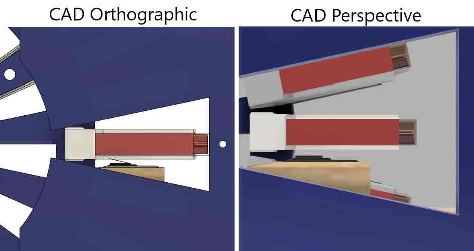
We found out the hard way that the iPad camera sees more like the perspective view than the orthographic view. This occasionally cauased the wrong bits to scan. As a result, we produced one more laser-cut piece to further close in the blinders.
My last big effort during final assembly was to create an electrical panel for the electrical components to mount to. Luckily, I did have some foresight that this would need to occur as a very last step. This was part of the inspiration for dividing the right acrylic panel of the box into two pieces. This allowed us to prove out the side-door and the window portion while waiting on the electrical components to be completed. The electrical components were simply mounted by laser cutting holes in the panel to match those on the components and by using nylon standoffs we were able to lift the components off of the acrylic backing in an electrically safe manner. Models for Arduino Uno were downloaded from grabCAD which allowed easy placement of the holes. Other components were measured and transferred into CAD by hand. Luckily, all of the tolerances worked by simply duplicating the spacing/size of these holes onto the acrylic pane.
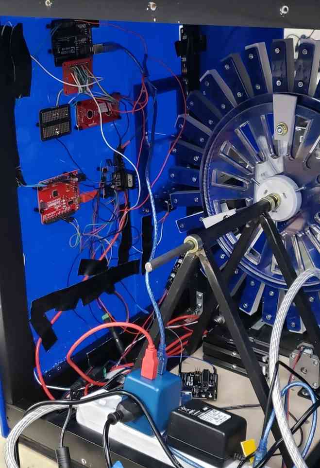
The cable management was still in process at the time of this photo’s taking, but this offers a good picture into how the various electronics were mounted. Duct tape was then used to manage the tangle of cables and keep them away from the movement of the wheel. One final hiccup was finding that the limit switch wires needed to be longer in order to reach the homing limit switch in a safe manner that cleared the movement of the wheel and other components. This was fixed by simply extending these wires and heat-shrinking the connections.