Week 14: Networking and Communications
Goals for the week
- Complete a few Hello World type tutorials for ESP8266
- Wirelessly send music files to my final project headset
- Move from the breakout board to the more integrated board
- ~Connect the device to Spotify or other music streaming services~
~ are stretch goals ~
Starting out with ESP8266
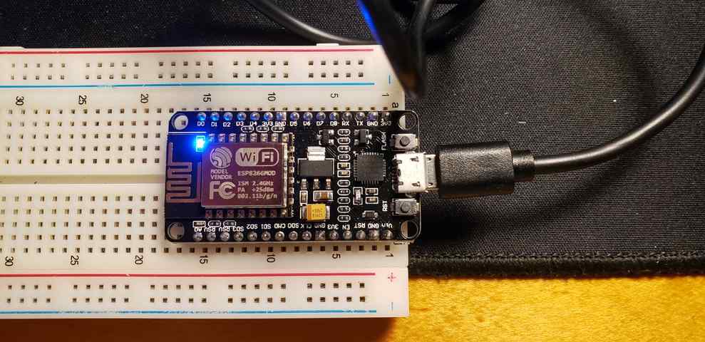
I chose to work with ESP8266 this week because I had one laying around that was aspirationally supposed to go into an old project that I never got around too… Redemption baby!
Setup
I started by following the instructions here to setup my computer to work with the ESP8266. I installed a few of the driver packages and set up the Arduino IDE accordingly.
Blinkie
I followed the tutorial here to get the built-in LED to blink. The only major difference I found between programming the ESP8266 module and Arduino was the need to hold down the flash button while plugging the module into the computer when you wish to send it a new sketch.
Hello Wifi
Continuint with the series of tutorials here, it was time to connect this thing to the internet! At first, I had a bit of issues connecting to WiFi, because I left the carrots “< >” in the following code,
// Attempt to connect to a specific access point
WiFi.begin("<your wifi access point name>", "<your wifi access point password>");
Eventually, I realized this and was able to retrieve the module’s IP address, pictured but also blocked out below for my protection.... Not that they would, but one of these fab hacksters could probably control my microwave with that little bit of information!
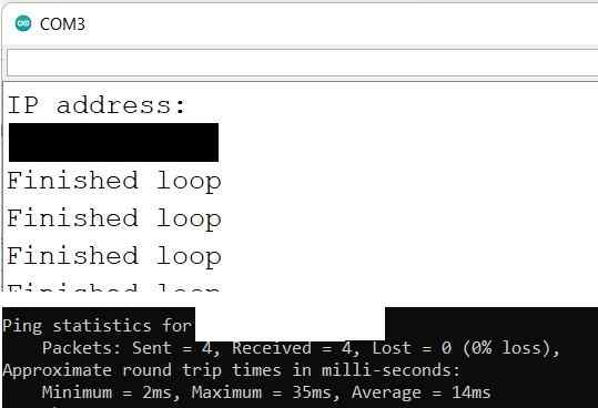
I was also able to ping it successfully from Windows Powershell.
MQTT Connect
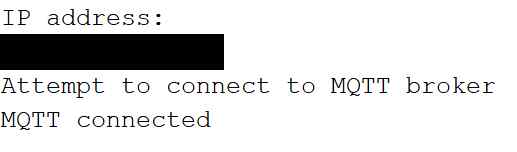
I have to be honest, this next tutorial to connect the module to an MQTT service went a bit over my head. I also had some trouble getting it to work. The serial monitor repeaditly read “Attempt to connect to MQTT broker” every 3 seconds, clearly unable to connect. After trying the tutorials full sample code, still to know avail, I wondered if it was a problem with the specific MQTT service it was trying to connect to, “iot.eclipse.org”. I was further tipped off because the webpage for that service gives a 404 error. Perhaps its no longer in service? Anyhow, I tried a few other services from this page. The first to work was “mqtt.fluux.io”.
Creating HTML page
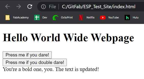
Somewhat inexplicably, this tutorial series took a hard tangent into webpage development, html, and JS. Having a feeling that it would loop back around, I humored it… and humored myself for that matter…
Connecting ESP to HTML
I haven’t had any luck with lesson 6 of this tutorial. My theory was this may have to do with me using a different MQTT service, but even playing around with that did not lead to any success. On another note, this page suggests it may have to do with my browsers same origin policy, but the solution there did not warrant any success.
On the paho documentation page, I noticed this quote,
This requires the use of a broker that supports WebSockets natively, or the use of a gateway that can forward between WebSockets and TCP.
Finally, on the gitHub page, I found this thread claiming the paho.mqtt.javascript project has been left broken and abandoned. This could be the reason I had trouble sending/receiving messages on my HTML page. From here on out, I read the rest of this tutorial but did not beat myself up that I couldn’t get it to work. Importantly, I understood most of it conceptually.
Streaming music to ESP8266
WiFi Radio MVP
Next, I will be following this tutorial to get the module running as a WiFi Radio. This will be relevant to my final project.
I carefully copied/pasted all of the code line-by-line, attempting to understand the core of what it is doing. My loose understanding is that the program is bringing in mp3 files from WiFi radio stations and sending them out of the RX pin via I2SNoDAC. It sounds like the ESP8266 does not have a DAC, whereas the ESP32 does.
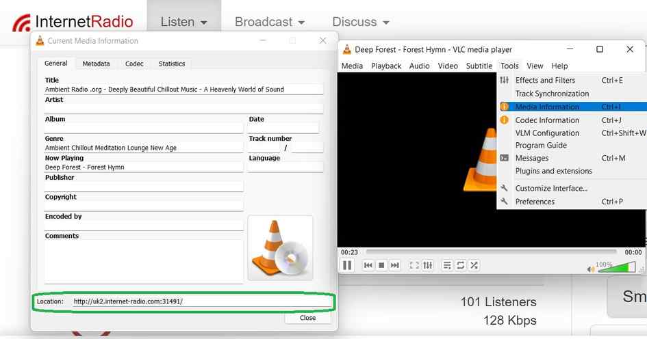
Discovering radio stations has been a treat. I settled on using https://www.internet-radio.com/, since the site the OP posted was in German. This site made it easy to download the .m3u files for the stations. I learned that an m3u file is a quick way to access these radio stations from a computers operating system, without needing to go through a web-browser. The tutorial then showed how to extract the links needed by viewing the media information in VLC player.
From there, the only difficulty was driving the speaker. The tutorial suggested using a transistor to this end, but I misplaced the one I had grabbed from the lab. Perhaps all the better, since in the long-run I would likely opt to use one of my pre-amps anyway. As the tutorial suggested, the pre-amp didn’t run so well off of the ESP8266’s 3.3V. This mirrors my experience driving the speaker with Arduino/AVR. Therefore, I decided to run it off of 5V supplied by the Analog 2 Digital discovery kit, knowing that eventually I would have 5V available from my AVR board on my final project. Here were the results,
As mentioned in the video, potential next steps are as follows:
- Include a reconnect() function in case WiFi drops out
- Add a button to cycle through different radio stations and/or silence
- Incorporate the serial commands as audio output such as “Connecting to WiFi”, “WiFi conncected”, etc.
- Load the program on my smaller ESP8266 board, which is more appropriately sized for my final project.
Improving WiFi Radio
Adding Button to change the radio station
I began by adding a button to change between various radio stations. I began this task by adding the different URL’s into an array. After trying an array of strings, it became clear that the code very much cared that “URL” remain a const char pointer. Luckily, it allowed me to easily turn it into an array of const char pointers with the following code,
//Radio station options
const char *URL[numStations] = {" ", /* theoretically silence */
    "http://us4.internet-radio.com:8258/", /* Florida classic Rock - https://www.internet-radio.com/station/douglassinclair/ */
    "http://us4.internet-radio.com:8073/stream"};  /*Ethereal radio - https://www.etherealradio.com*/
which allows me to call up the various stations individually. However, I ran into trouble when I attempted to call multiple different stations in a row. I was getting something called an exception 29 error. According to this thread, this can occur when trying to rewrite a protected area of memory. This was a tough problem to overcome because I don’t have a full understanding of pointers and their uses. Finally, after googling some of the code, I came across this project which seemed to have overcome the same issue by using a function called stopPlaying() to overwrite these variables.
void stopPlaying() {
  Serial.printf("Stopping MP3...\n");
  if (mp3) {
    mp3->stop();
    delete mp3;
    mp3 = NULL;
  }
  Serial.printf("MP3 Stopped, Stopping Buffer...\n");
  if (buffmp3) {
    buffmp3->close();
    delete buffmp3;
    buffmp3 = NULL;
  }
  Serial.printf("Buffer stopped... Stopping File ...\n");
  if (filemp3) {
    filemp3->close();
    delete filemp3;
    filemp3 = NULL;
  }
  if (outmp3) {
    //    filemp3->close();
    delete outmp3;
    outmp3 = NULL;
  }

  Serial.printf("STATUS(Stopped)\n");
  Serial.flush();
}
By rewriting these variables, I was then able to reassign them to a new radio station. I utilize similar logic later on when adding in custom sounds such as for the pause button.
For now, I am successfully able to change between 3 different stations by pressing the flash button. Note, the flash button can be used as an input. It is initialized by writing pin 0 as an INPUT_PULLUP. This is useful since I do not have a separate switch with me at the moment. Eventually, I will of course swap this with an external button.
Adding Custom Sounds
Since the final device will be a headset with limited user interface, I wanted to implement custom audio commands that occur during significant events such as changing the channel. Luckily, I quickly found this tutorial which easily shows how to play custom .wav files that are stored in memory on the ESP8266. To create the wav files, I followed the tutorial and downloaded Audacity. After recording and exporting them as .wav files, I used tomeko.net to convert .wav files to hex format. Then these files are simply saved in the Arduino sketch’s folder and referenced via #include “viola.h”. Following the tutorials lead, I built out a proof of concept from the ESP8266 example, PlayWAVFromPROGMEM. This worked out of the box, so replacing the viola.h file with my own custom sounds was as simple as replacing the hex code within the file. Then I duplicated the file to create the following custom sounds,
// Include custom sound files
#include "ethereal.h"
#include "venice.h"
#include "florida.h"
#include "pause.h"
//#include "resuming.h"
These all worked beautifully and could be called on command. For some reason “resuming.h” is giving me an “Id returned 1 exit status” error. Following this thread, this may have something to do with the file being open. I think I tried to edit this code via visual studio code rather than the Arduino IDE, because when I retried building the file using only the Arduino IDE, the issue seemed to have resolved itself. Correction, the issue returned when I uncommented more code and called the function playResuming(). For now, I will simply omit this sound and perhaps come back to it.
Adding a pause button
Then I turned my attention to adding a pause function. Well, technically since this is radio that cannot be paused, it will be more like a mute button. That said, I first made the mistake of trying to implement a “blocking function” that used delays(). Per this thread, ESP8266 WDT does not like blocking functions. Anywhere I am using delay functions, which can mess up the clock, I need to instead lean on the clock and use millis() to do timing. When I did this wrong, I was getting errors like disconnecting from WiFi and the chip resetting. I think I’ve hammered out most of these bugs, but occasionally the chip still resets. I need to make sure nothing about my code is keeping the main loop from running for too long. Perhaps my functions being called within other functions could be the issue.
For now, I turned the pause function into essentially a mute function. And the resume into an unmute function using the setGain command.
void nowPause(){

  clearCustom(); //clear variables to make way for pause announcement
  playPause(); //announce pause
  pauseStatus = true; //used in the main loop to determine button function
  Serial.println("Initiating pause. Press button again to play");
  out->SetGain(0); //set volume of radio to 0

}

void nowResume(){

  out->SetGain(1); //set volume of radio to 1
  pauseStatus = false; //used in the main loop to determine button function
  Serial.println("Resuming");
}
These functions are called in the main loop and seem to work correctly.
WiFi Radio Results
Remaining Errors
Occasionally, I am still getting the exception 29 error, suggesting that I am trying to overwrite memory that should not be overwritten. Additionally, I occasionally am still getting a Soft WDT Reset error, possibly suggesting that something is blocking the main loop for too long.
Integration in final project
For more information on how this WiFi is integrated into my final project, see the Music section on my final project page. Long story short, I decided the easiest way to combine the cancelation signal coming from my 1614 Audio board with this WiFi radio audio, would be through analog circuitry. Specifically, these two signals are combined using a summing amplifier circuit. With that said, I understand that this will not count towards the networking assignment. Luckily, I discovered another need for I2C communication between my two boards in my final project. This is discussed below.
Revisiting Networking
After all this work on the ESP8266 radio, I was dismayed to hear that connecting ESP to other boards over I2C is difficult if not impossible. At a minimum, Neil recommended the ESP 32 over the 8266. As a result of this, and all of the work I have put into the ESP8266 project, I have decided to split my work into two segments. In order to fufill the networking requirement, I will now begin working on having two ATTINY chips talk to eachother over I2C. Time permitting, I will revist the WiFi radio as it pertains to my final project. Assuming the networking with ESP8266 is a bust, I think I should be able to combine it with the audio coming from the ATTINY project using a summing OP-AMP circuit instead of networking.
Beginning with AT-TINY
Since I am behind the ball on this assignment, I am greatly benefiting from all of the awesome work my teammate Barbara Morrow has done on the subject of Networking. Specifically, she helped us setup our group assignment where we had one parent 1614 board talking to multiple children 1614 boards. Additionally, her personal documentation page and links therein have been a very good resource for me getting started.
Following her lead, I was able to get a very bare minimum I2C example running on two 1614 breakout boards without much fuss.
Parent code,
// Wire Controller Reader
// Adapted from Barbara Morrow's version of Nicholas Zambetti's code <http://www.zambetti.com>

// Demonstrates use of the Wire library
// Reads data from an I2C/TWI peripheral device
// Refer to the "Wire Peripheral Sender" example for use with this

// Created 29 March 2006
// adapted on 18 May 2022

// This example code is in the public domain.

#include <Wire.h>

void setup() {

  Wire.begin();        // join i2c bus (address optional for master)
  Serial.begin(9600);  // start serial for output
}

void loop() {
  delay(500);
  Serial.println("Requesting data from peripheral device #2");

  Wire.requestFrom(2, 15);    // request peripheral device #2 to send over 15 bytes

  while (Wire.available()) { // peripheral may send less than requested
    char c = Wire.read(); // receive a byte as character
    Serial.print(c);         // print the character
  }

  Serial.println("");

  delay(500);

}
Child 2 code,
// Wire Peripheral Sender
// Adapted from Barbara Morrow's version of Nicholas Zambetti's code <http://www.zambetti.com>

// Demonstrates use of the Wire library
// Sends data as an I2C/TWI peripheral device
// Refer to the "Wire Master Reader" example for use with this

// Created 29 March 2006
// adapted on 18 May 2022

// This example code is in the public domain.

#include <Wire.h>

void setup() {
  PORTB_PIN0CTRL |= PORT_PULLUPEN_bm;
  PORTB_PIN1CTRL |= PORT_PULLUPEN_bm;
  Wire.begin(2);                // join i2c bus with address #4
  Wire.onRequest(requestEvent); // register event
}

void loop() {
  delay(100);
}

// function that executes whenever data is requested by master
// this function is registered as an event, see setup()
void requestEvent() {
  Wire.write("hi from Board 2"); // respond with message of 2 bytes
  // as expected by parent
}
Results,
Implementing into final project
As time went on, it became clear that I would need to use two ATTINY 1614 boards for my final project. This was primarily driven by spacial constraints and the number of ADC peripherals available. Specifically, each 1614 chip had two instances of the ADC available where I needed 3 (audio, volume potentiometer, delay potentiometer). Therefore, I decided to split the project into a controls board and an audio board, and deliver the status of the controls to the audio board via I2C. This had the additional benefit of allowing the audio board to focus entirely on the audio signal processing. Rather than having to constantly check the status of potentiometers, this board could now simply wait for commands to be sent from the other board via I2C.
Somewhat counterintuitively, Adam Harris helped me realize that the best way to manage this would be to make the controls board the parent and the audio board the child. Following the documentation here, I began by duplicating the “Controller Writer” configuration.
This worked perfectly well for a hello world example, but things began to break down when attempting to send the status of the potentiometers over. After some debugging, I found the issue to be datatype related. I was attempting to send the pot values as ‘byte’ and receive them as characters. Once I began sending/receiving as a byte, the data began to come through more clearly.
The next challenge was to distinguish between volume data and delay data. After some googling, I came across this documentation on how to create a ‘struct’ that can contain multiple variables of multiple variable types.
//Parent (Controls) Board Struct
//create a structure of datatypes to be sent over I2C
struct I2cTxStruct {
  char valType;       //1 byte
  byte potOut;  //1 byte
 };


//Child (Audio) Board Struct
//define structure for incoming I2C data
 struct I2cRxStruct {
  char valType;       //1 byte
  byte potOut;        //1 byte
};
This allowed me to send data such as “v 255” or “d 122”, and enabled the audio board to sort out what is what using a simple if statement when new data is received.
      if (newRxData == true & rxData.valType == 'v') {
//          showNewData();
          changeVolume();
          newRxData = false;
      }
      else if (newRxData == true & rxData.valType == 'd'){
//          showNewData();
          changeDelay();
          newRxData = false;
      }
The last challenge was to use the volume data effectively. It was nontrivial to change the amplitude of the signal without changing the offset. Eventually, I settled on this equation within the DAC_setVal function.
 void DAC0_setVal(uint16_t val)
 {
   tempVal = 127 + (int)((((float)~(val >> 2))-127.0)*((float)audioLevel/255.0));
   DAC0.DATA =  tempVal;
 }
With all that said, the I2C communication was successfully implemented in my final project in both ANC7 and ANC8. Here was the first attempt, ANC7.
And here was the final attempt, ANC8.
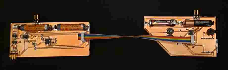
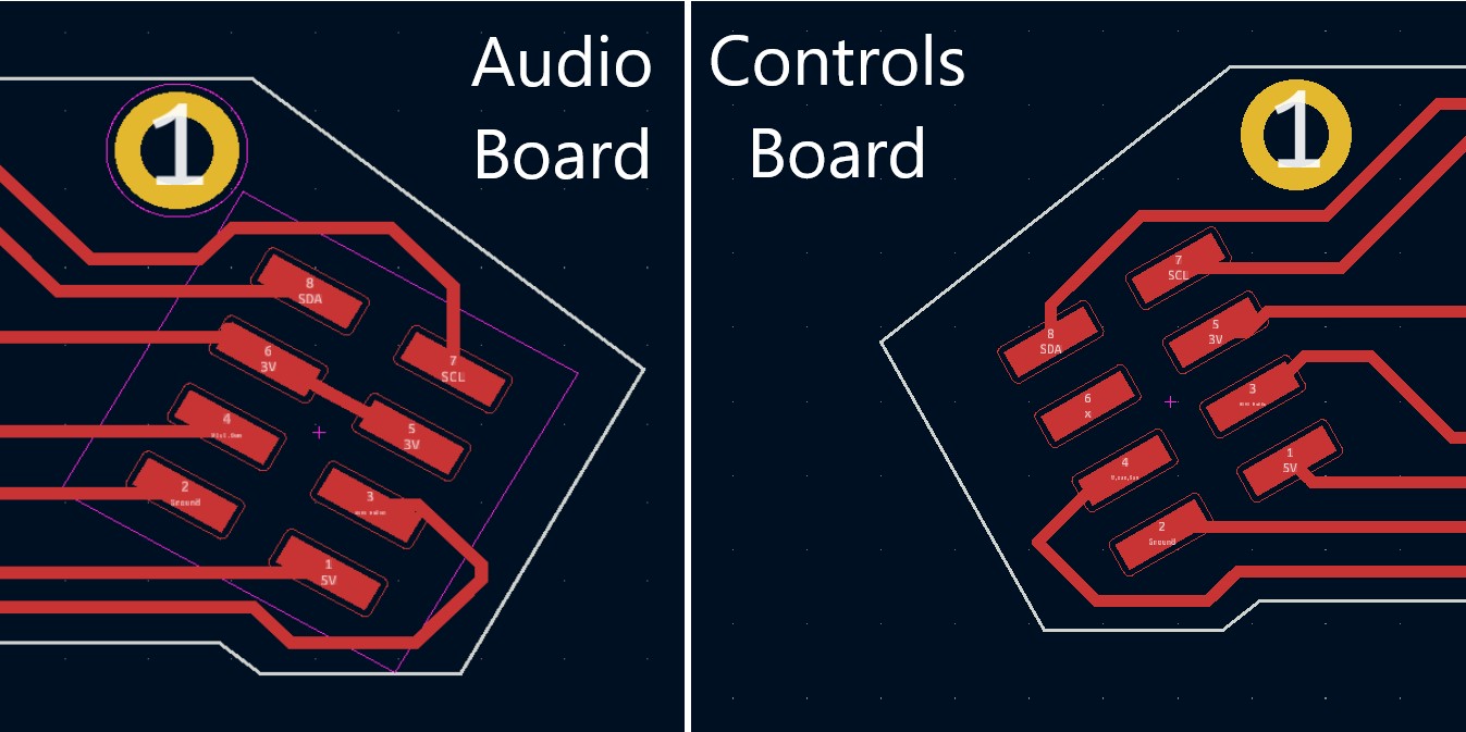
Here is a detailed look at the connector which connects the two boards. As you can see, SDA and SCL are the top two ports on the ribbon connector.
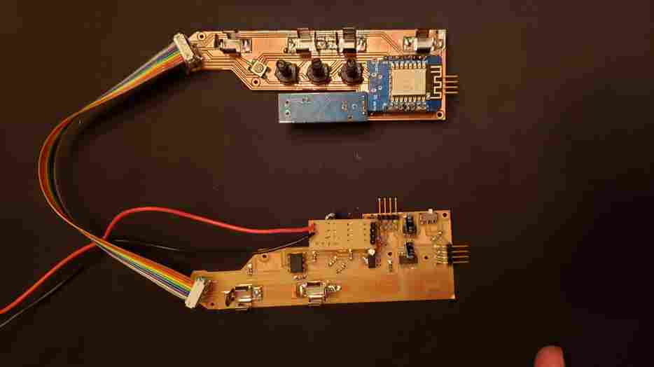
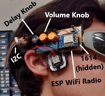
This volume/delay control can be seen successfully working at the 50 second mark of my final project video, found here. These commands are being passed between the two boards via I2C communication. Here is a labled close-up of the controls board.
Lastly, the full code for my final project, which includes the I2C communication, can of course be found here.
Group Project - Send a message between two projects
Documentation on our groups efforts to send messages between multiple projects can be found here. My contribution was at the very end to bring in my AVR 1614 board as the third child in the chain.
- The “under the hood” of the internet gets extremely complicated extremely quickly. Attempting to work with MQTT taught me that.
- Beware of blocking functions. These freeze the chip from being able to perform anyother tasks, including mission critical ones like remaining connected to WiFi.
- I2C is two wire communication but all of the data is transferred over the SDA line whereas the SLC line is simply for timing the communications. 4.
Note: All design files and images can be accessed in my git repository found here.
All works shared on this site 'A Fab Academy Journey with Charlie Horvath' by Charles W. Horvath are licensed under Attribution-NonCommercial-ShareAlike 4.0 International![]()
![]()
![]()
![]()