Week 9: Molding and Casting
Goals for Molding and Casting
- Mold or cast something with 3D features using a machined mold
- Establish a firmer understanding of molding/casting processes
- ~ Make a part for my boat that serves dual functions ~
- ~ Make a part that is useful towards my final project ~
~ are stretch goals ~
Fiberglass Boat Part
So I learned a critical soft skill this week: knowing when it’s time to give up on a project or concept. That being said, feel free to skip past this section since I eventually abandoned this project and never got to the stages of molding/casting.
Inspiration
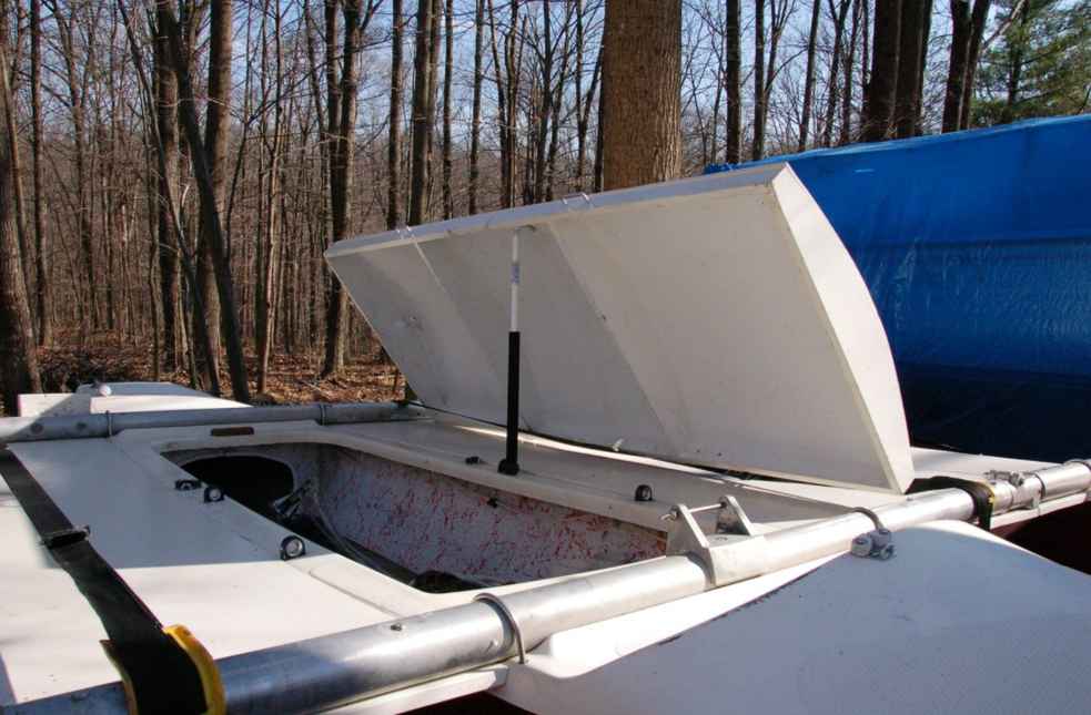
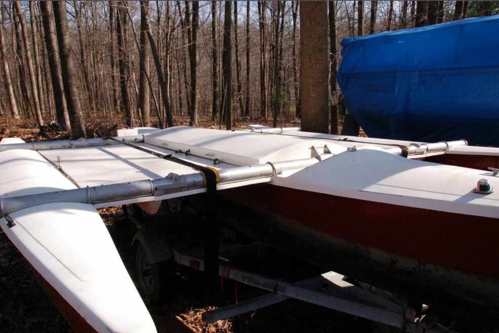
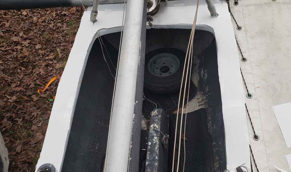
So I had an idea for a fiberglass boat part that I was quite excited about. One of the issues with my Trimaran sailboat is that the cockpit is not auto-bailing. That is to say, unlike some sailboats, it has no method of removing water while the boat is submerged in water. And since I’d like to take the boat in the ocean someday, this could cause huge issues, if for instance the boat took a wave and the cockpit began to fill up with water. As such, I am in need of a water-proof cover to cover the cockpit.
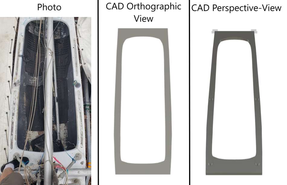
Someone with the same boat recognized the same issue and developed a fiberglass cap to cover the cockpit. The specific owner is unknown to me, but these images we’re found here.
I liked the problem they were trying to solve and the execution, but I had different ideas for a solution. I wanted to retain the ability to use the cockpit normally, without having to completely remove the cover. After going through a few concepts, I settled on sliding fiberglass parts that would connect/disconnect on the centerline via magnets. They would have two modes and serve as a cover for the cockpit while closed and benches while open. I love dual functionality, so this concept had me really excited.
Tracing my boat top
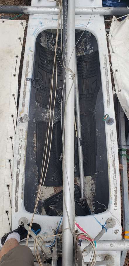
So I needed to design a part around the deck of my boat. Here is the best top-view image of my boat I could gather.
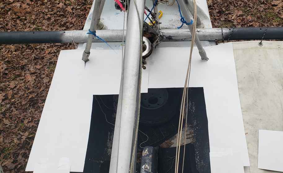
 The best method I settled on for this was to trace the shape of the top-deck into posterboard and cut out the rough shape with a razor blade. I estimate this method was accurate to about the 0.25”, which would be sufficient to my needs.
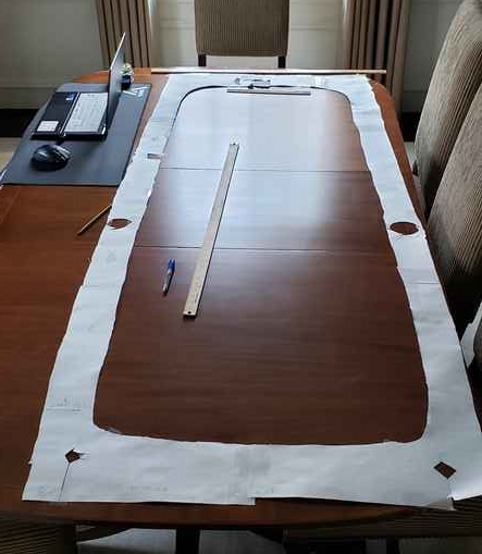
Then I was able to transfer this deck shape into CAD one coordinate at a time, from the comfort of our Dining room.
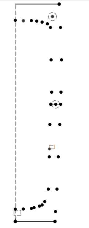
Which I then connected via splines to produce this:
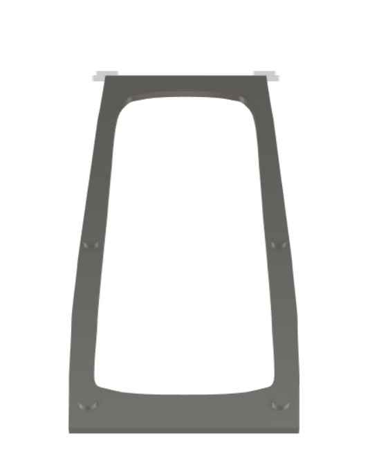
This next image shows why this may have been a worth excercise as opposed to just “eyeballing it”. From the image I took, and the true eyeball vantage I had while taking it, I believed that the boat had a major taper towards the aft of the boat. However, the measuring and subsequent drawing of the hull revealed that this was simply a matter of perspective. The orthographic top-view of the boat reveals the true shape is much more symmetric across the midline and less-tapered. Then, using Fusion’s perspective mode, I was able to recreate the shape in CAD. See below.
Concept and eventual abandonment
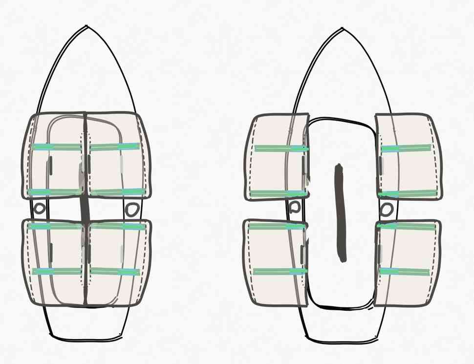
So the idea was to mold a 3D curved shape out of fiberglass that could slide along the deck surface between “cover-mode” and “bench-mode”. To accomplish the sliding, I would use aluminum T-tracks and runners. To lock the seats in place, I would use Neodymium bar magnets and similarly shaped steel bars. These magnets were to be inserted into the part between layers, such that no additional attachment was needed. Here was a rough 2D sketch and then mockup in CAD.
My excitement for the project was growing. That is… until I sat down to budget it out.
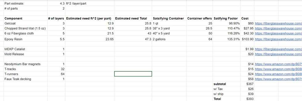
To build just two of these 4 parts, would cost $393 in materials. It turns out fiberglass inputs are extremely expensive and the B.O.A.T acronym rings true…

Well cheers to knowing when to put a project down. As cool as this would be, the functionality is simply not worth the cost. Not to mention, this concept didn’t even close up the entire cockpit, and might not even fully stop a wave from filling it with water. I think there may be a cheaper way to do it such as covering plywood with fiberglass and omiting a mold, but that would not satisfy the assignment. Ahhhh, so on to the next thing.
Final Project - Speaker Box for Bone Conducting Transducer
Design of Cover & Speaker Box
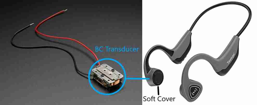
So with the boat parts off the table, I decided to apply the weeks assignment to my final project. I had selected this bone conducting transducer to implement into the headphones. I aimed to create a cover for it out of soft material such as silicone or rubber, similar to what exists on my off-the-shelf BC headphones.
Adafruit has a and related tutorial for this unit that includes a 3D printed housing, which has offered me a great headstart. Better yet, I found a GrabCAD user Josh Chang had created an aesthetic to-scale CAD model for this exact transducer. I will be careful to verify these dimensions once I have the transducer in hand, but still, what luck!
I began by modifying the existing printed housing by breaking it into two pieces that would pinch the soft rubber cover in between. In practice, this proved to be a little more difficult than I first anticipated. Working with very small components here and design for assembly (DFA) is a real challenge here. Here is the design that followed.
The printed parts could be adjusted down the road, but for time’s sake, its important I get the molded cover in a usuable shape the first time I try to mold it. Therefore, I went ahead and 3D printed everything out of PLA to try and get a rough idea of how it will come out and what can be improved.
This test print led to a few adjustments to the design. Mostly changing fit tolerances and adjusting the thickness of a few thin features. The largest change was that I beefed up the “inner-piece” and made the wedge portion less compliant. Additionally, I increased the size of the lip on the molded cover and gave it more clearance with the outer wall of the outer-shell. The test print helped me realize how small everything was and remember, “everything looks bigger in CAD”.
At this point, for the sake of time, I decided that the rubber cover part was far enough along to move towards manufacturing. Assuming I get the molded component near correct, I can always adjust the 3D printed interface and speaker box construction after the fact.
CAM for Molding
To create the 2 mold halves of the 2-part mold, I created a rectangular box, and subtract out the rubber component using Fusion’s combine feature. Here, I found it was best to check the box keep tools so that my rubber cover component remained intact. Then I split it in two using the split body function. Lastly, I embossed and extruded a feature around the perimeter as a registration feature. Here is the result.
Then I adjusted the size of the molds to fit two pieces of wax stock we had in the shop. Additionally, to reduce the number of toolchanges, I decided I would machine both halves of the mold in one shot. Therefore, I positioned the two mold halves side-by-side and combined them into one body so that the CAM software could process them together as one. Time will tell if this is a good practice, considering I will technically be machining two separate pieces of stock side-by-side.
Here is the fusion simulation of the final operations.
One thing I realized at this point is that due to the thickness of the stock, I would be unable to machine the vent holes. Therefore, I decided to machine these with a hand-drill as a post process.
Machining molds
Most chips award?
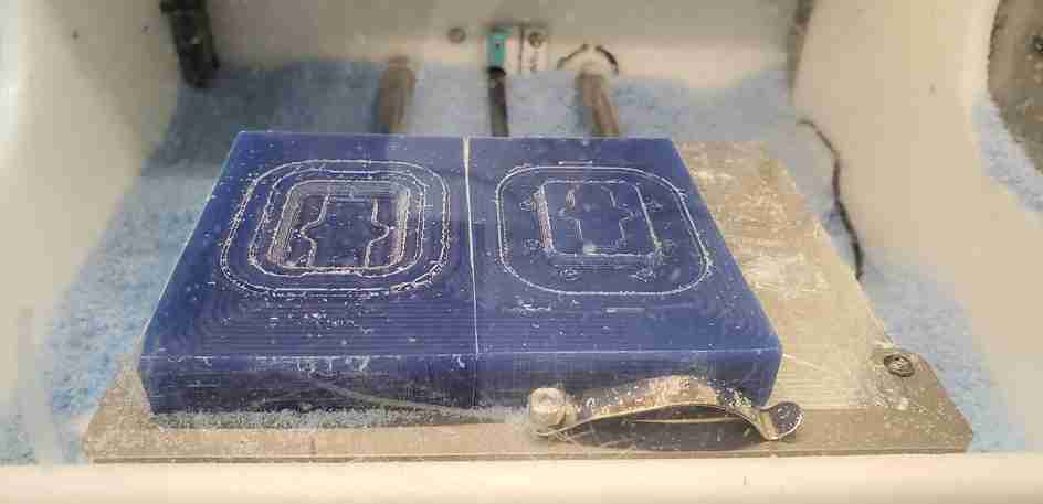
Progress after OP1 - 1/8” FEM roughing
Progress after OP2 - 1/32” FEM roughing/finishing edges
Final molds after OP3 - 1/16” BEM finishing
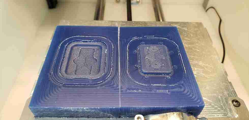
The only post-processing I did was drilling vent-holes into the top half of the mold, and then wiping everything down with acetone to remove chips/dust.
Using the molds
To select materials, I referenced our groups material guide we created for our group work found here. At this stage, I’m not totally sure which material properties I need for this cover, so I wanted to try a range. Since I’m still in the discovery phase, I really just went for it. So due in part to availability and ease of use, I settled on testing 3 materials.
Prior to pouring these materials, I sprayed the molds down with mold-release and waited the reccomended 5 minutes. In general, I way overmixed and overpoured these materials. That said, I got better as the process went on. After the fact, I checked Fusion 360 which says this component is only 1,085 mm^3 or 1.085 ml in volume. It turns out 1 mm thick makes for a very small part… go figure!
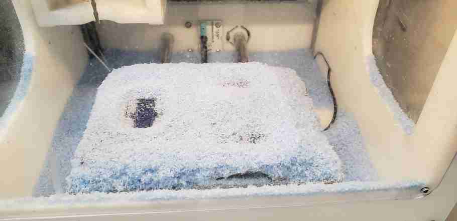
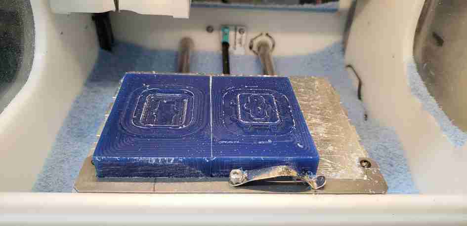
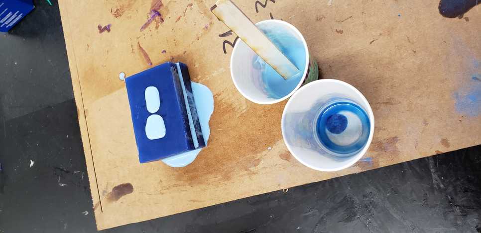
Here is the 300 curing between the two mold halves.
Its hard to see under the excess resin, but this time I marked the interface between the two mold halves using a silver paint pen. This made it much easier to line up the registration features of the two mold halves. Here are the results of all 3 tests.
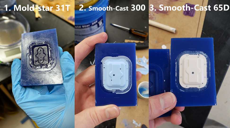
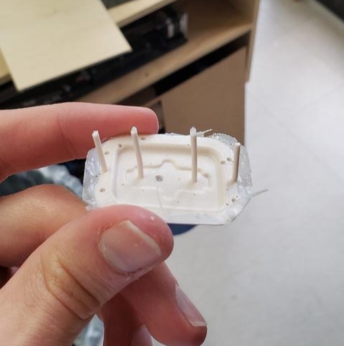
This third and final pour was far and away my best one yet. I hardly used any liquid whatosever. As such, the vent holes properly served there purpose, and even stayed in-tact as I removed the component.
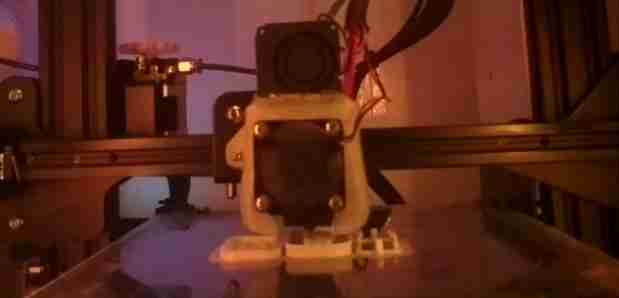
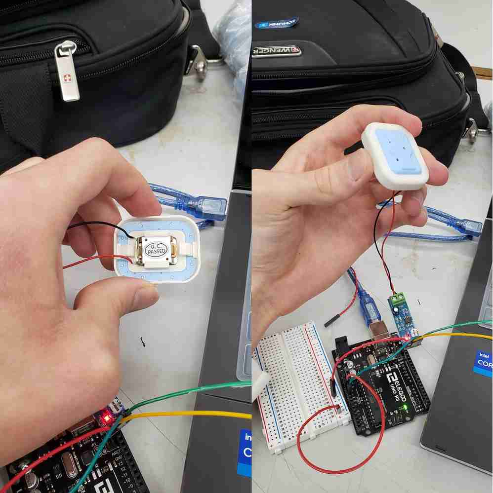
In parallel, I 3D printed the speaker-box housing components using the Prusa mini printers in the lab. Much to my suprise, the BC speaker cover fit into the assembly perfectly on the first try! The BC transducer was tight and secure between the cover. Considering I didn’t even have the transducer in-hand when I began this process and was relying on a CAD file generated from the grabCAD community, I had anticipated atleast a few more iterations of these printed components before this 4 piece assembly would work. So everything snapping together was a satisfying result!
With apologies to all my State fans out there for the accidental UNC colors… To all the UNC fans out there, my sister says,
“Nothing is an accident” - Avery Horvath on 3-31-22. 1-day before Duke/UNC meet in the final four
That being said, the BC transducer is behaving unexpectedly now that it is pressed up against a hard cover. It seems that I’ve given it a woofer to project sound from. In theory, we want the skull to be that woofer, not the cover. So not only does this reduce transmission to the skull, it increases noise leakage to the ambient environment. This result could mean a lot of things and will be discussed at length on my final project page, here. Additionally, in this regard, I will compare/contrast the performance of these 3 materials against the bare metal component. Long story short, I need to check my assumptions.
Discussion of hard vs. soft materials
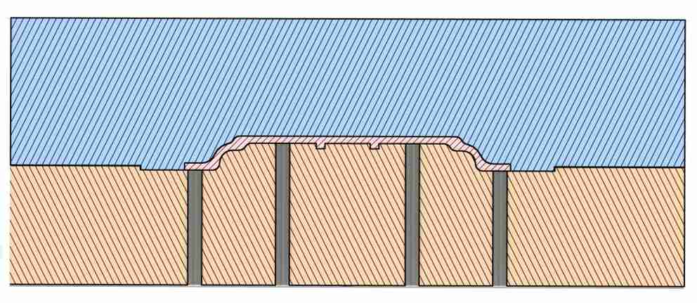
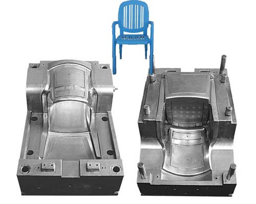
Fab Academy has taught that we should use hard molds for soft parts and soft molds for hard parts. In general, I think this is a good rule of thumb for the purposes of Fab Academy. That said, I would point the instructors towards industry where hard molds are quite often used to mold hard plastic parts. Here is an example given of a hard HDPE part being molded in a 2-part hard mold. Image credit, ecrater.com.
If I were to speculate why this works, it is for two reasons.
- Even hard plastic parts such as HDPE or PET, have some pliability to them and are able to flex as needed when being removed or punched from a mold.
- Very often, two part molds are used such that no part of the mold ‘blocks’ the part from being removed.
With these thoughts in mind, I developed this two part mold with both hard and soft materials in mind. The soft material was the easiest to remove, but the hard materials I chose had some pliability and I did not have much issue removing them from the mold.
With all this in mind, I would advise Fab Academy to consider adjusting the hard mold <-> soft part from a requirement to more of a rule of thumb, because I think there are exceptions to this rule as is evident by my work on this page.
Link to Group work
Our group comparison of different molding materials in our lab can be found here.
- General rule of thumb: To mold something hard, you need a soft mold, and vise versa.
- If both are hard, you can’t have overhangs and need draft angles to remove it.
- Fiberglass is pricey. Especially parts made from scratch with fiberglass methods.
- Knowing when to give up on a project and swollow pride is critical.
- Good reminder that everything looks bigger in CAD.
- Check volume of a part prior to mixing cast materials. Pouring less is more.
- Once a mold is created, production is quick, easy, repeatible and fun.
- Going forward, I need to create deeper registration features to line up the mold halves.
- Wax is easy and forgiving material to machine. Next time I can up feeds/speeds.
Note: All design files and images can be accessed in my git repository found here.
All works shared on this site 'A Fab Academy Journey with Charlie Horvath' by Charles W. Horvath are licensed under Attribution-NonCommercial-ShareAlike 4.0 International![]()
![]()
![]()
![]()