Week 15: Interface and Application Programming
Goals for Interface and Application Programming
- Build an application that works with a derivative of the I/O board created during inputs/outputs week
- Craft the interface to be useful towards my final project
~ are stretch goals ~
Processing Tutorials
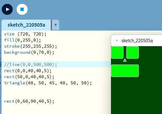
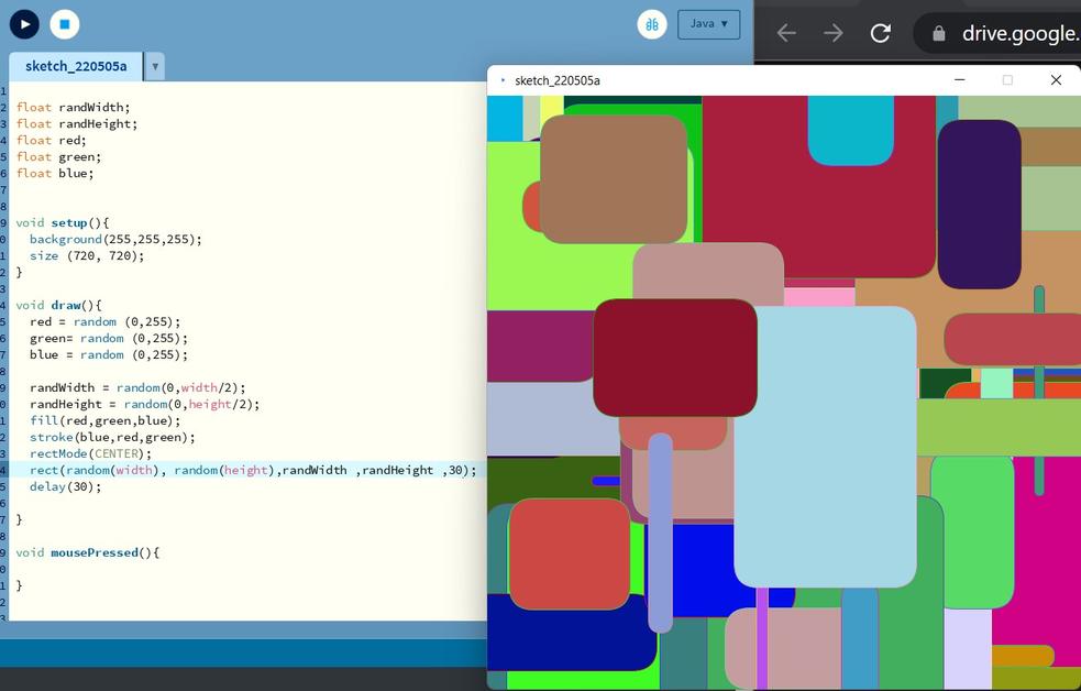
Almost totally at a loss for what to do this week, I decided to begin with our labs recommended “Processing” tutorials. I quickly came to find out that Processing is a very user friendly tool for creating simple user interfaces and graphical representations, and operates much like the Arduino IDE. This will be a good jumping off point for me to work towards something useful to my final project.
Tom’s Introduction to Processing
I got through 4 of Tom’s tutorials which are grea. Here are the links,
- Tom’s processing tutorial I
- Tom’s processing tutorial II
- Tom’s processing tutorial III
- Tom’s processing tutorial IV
Here are some of my results.
Connecting Processing to Arduino
Tom directed us to many options for Arduino-Processing tutorials,
- Maker.pro - Learn how to connect the Arduino to the Processing IDE…
- Sparkfun.com - Connecting Arduino to Processing
- Arduino.cc - Visualization with Arduino and Processing
- howtomechatronics.com - Processing
I decided to start with the maker.pro tutorial since it implements a potentiometer. This is something I’ve been wanting to experiment with anyhow in order to program a delay function for the noise cancelation circuit. Here are the results,
So my next task was essentially to merge this demo, with my code from inputs/outputs week, in order to build a delay function into my board. This work is relevant to my final project, which can be found here. For more context into the device I am adding a delay too, look under the ANC2 section. For more context into why add a delay, look under the section labled ANC5.
Developing Arduino Code
Developing the code was not an easy task for me. I set about trying to create a buffer of samples. For instance, the program will store 255 samples in an array at any given time. When a new sample comes in, the oldest sample will be overwritten. Then once I have this array, I can vary which bits are being written to and which are being read from. The size of that buffer or delay, can then be controlled with a potentiometer. As noted in the ANC5 section of my final project page, one challenge that will need to be overcome is that the sample rate can be inconsistent, so the program will need to have a live updated sample rate if I would like to dial in a specific time delay.
One of the earlier challenges to this code, was figuring out how to round the corner while writing to the buffer. Avery helped me through this by having me implement a series of if statements. This code is well documented with comments below.
 while (1)
   {

     // if we have filled the buffer
     if(counterBuffer == bufferLength){

        //if this is the first time we have filled the buffer
        if(bufferFilled == false){
          //calculate the samplePeriod
          samplePeriod = (micros() - startTime)/bufferLength;
          //print the sample period to processing, which should be the first value sent through
          Serial.println(samplePeriod);
          //tell the program that the buffer has been filled atleast once
          bufferFilled = true;
        }

        //reset the counter to the start of the buffer
        counterBuffer = 0;
     }

     // if we have filled up to the delaylength
     if(counterBuffer == delayLength){
        //tell the program that the delay has been filled atleast once
        arrayFilled = true;
     }

     //set the value for the potentiometer
     pot_output = analogRead(pot_pin);
     //If pot value has significantly changed
     if (pot_output > (pot_output_last+5) || pot_output < (pot_output_last-5)){
        //call the change delay function to send a new value to processing
        changeDelay();
     }

     //write a new value to the array
     adcVal[counterBuffer] = ADC0_read();

     //if the full delay has been filled atleast once and the full buffer has been filled atleast once
     if(arrayFilled && bufferFilled){

        /*The next two if statements help the buffer 'round the corner' and handle negative numbers */

        // if the write position is less or equal to the delay
        if(counterBuffer <= delayLength){

          //Output a value from the array from position total length + write position - delay length
          DAC0_setVal(adcVal[bufferLength + (counterBuffer - delayLength)]);

        }
        // if the write position is more than the delay
        if(counterBuffer > delayLength){

          //Output a value from the array from write position - delay length
          DAC0_setVal(adcVal[(counterBuffer-delayLength)]);

        }
     }

      //Add 1 to the write position variable
      counterBuffer = counterBuffer+1;

   }
This is only the main while loop. My full code will be available in my repo as a part of week 15 files.. I ran into many errors along the way. One recurring error occured in my if statements where instead of writing if(bufferFilled == false){ I would write if(bufferFilled = false){. This sort of error took a lot of time to diagnose because that section of code would not execute.
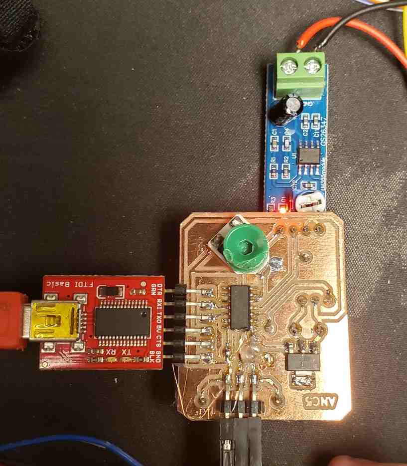
Another difficulty was getting serial to work with the ATTINY 1614. In previous weeks, I had used an Arduino with 328P chip removed in order to pass through serial commands. My team recommended FTDI cable as an easier way to achieve this same thing, and they were right. So my setup was having my 1614 breakout board in a breadboard, hooked into both an Arduino for jtag2UDPI programming and an FTDI cable for serial communication. I found the key was to only use one USB port on the computer, which forced me to unplug one device to plug in the other. This kept me from accidentally plugging the arduino and FTDI in to the computer at the same time, which could lead to too much power going to the chip, or worse, to my computer. Establishing this serial communication was critical to the next step, which would be connecting this code to processing.
Developing Processing Code
I wanted to send two different datatypes over to proccessing. The sample period and the delayLength as a function of the potentiometer. I figured there is probably a best practice way of doing this whereby both data points are sent over as a part of one long string at which point they are parsed into two separate data points on the other side. However, for times sake, I have settled on the first datapoint communicating the sample period with all future data points being considered as delay values. This was easily established using boolean variables to track whether the data was first or otherwise. This is a messy way to do it because the sample period could change overtime and its also open to being buggy. That said, it will have to do for now.
Again, this code is well documented and explained below.
import processing.serial.*;    // Importing the serial library to communicate with the Arduino

Serial myPort;// Initializing a vairable named 'myPort' for serial communication

int delayLength; //a variable to track the delay length, as communicated by ATTINY

int delayLengthLast; //a variable to track the previous delay length

int samplePeriod; //a variable to track the sample period as communicated by ATTINY

boolean firstSerialEvent = false; //a boolean variable to track whether the data is the first datapoint or otherwise

//setup function
void setup(){

  //window size
  size (750,255);

  //print available COM ports to terminal
  print(Serial.list());
  print('\n');

  // Set the com port and the baud rate according to the Arduino IDE
  myPort = new Serial(this, "COM13", 57600);

 //denotes the char type to end a data aquistion on when receiving the data from the Arduino IDE
  myPort.bufferUntil ( '\n' );

}

//function to handle serial data
void serialEvent  (Serial myPort) {
  //save the previous delay length for safe keeping
  delayLengthLast = delayLength;

  // if this is the first datapoint
  if(firstSerialEvent == false){
    // recover this data as an integer into samplePeriod
     samplePeriod = int(float(myPort.readStringUntil('\n')));
     print("The Sample Period is ");
     println(samplePeriod);
  }

  // if this is not the first datapoint
  if(firstSerialEvent == true){
    // recover this data as an integer into delaylength
    delayLength = int(float(myPort.readStringUntil('\n')));
    println(delayLength);
  }
  //denotle that atleast one datapoint has been recovered
  firstSerialEvent = true;
}

//draw function
void draw(){
  //set the shape and background colors
  fill(255);
  stroke(0);
  background(0,0,0); // Initial background color, when we will open the serial window

  //font size
  textSize(32);

  //create some of the known strings to be displayed
  String s = "# of Delay Samples"; //lable for delay samples column of data
  String s1 = "Time Delay (μs)"; //lable for time delay column of data
  String s0 = "0"; //lower bound for delay samples column
  String s255 = "255"; //upper bound for delay samples column
  String sT0 = "0000"; //lower bound for time delay column

  //setup the more dynamic variables to be displayed
  int sT255 = samplePeriod*255; //upper bound for time delay column
  int currentDelay = samplePeriod*delayLength; //display of the current time delay value

  //Create visual display for # of delay samples
  text(s,200,(height/2-32));
  text(delayLength,200,(height/2));
  text(s0,200,height);
  text(s255,200,32);

  //Create visual display for Time delay column
  text(s1,500,(height/2-32));
  text(currentDelay,500,(height/2));
  text(sT0,500,height);
  text(sT255,500,32);

  //create delay slider visual
  rectMode(CORNERS);
  rect(10,(255-delayLength),160,255);
}
This came together quite nicely and was much easier than the arduino code. Parsing the data and appropriate use of the conversion functions such as int() and float() took some getting used to.
Here are the results.
Next steps are to implement this all into a milled PCB board that will bring me one step closer to my final project.
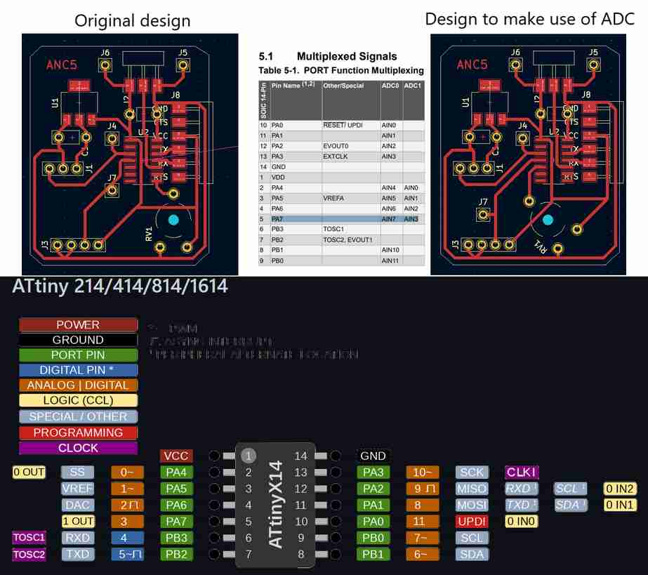
Updating I/O board in KiCAD
I was able to update my I/O board to include FTDI connection and the potentiometer with relative ease. I ran into one hiccup which was that I realized I was using PB1. This pin does allow for analogRead() but does not have direct access to the ATTINY’s ADC. Therefore, I switched over to using PA7 in case I’d like to use the bare metal commands later on.
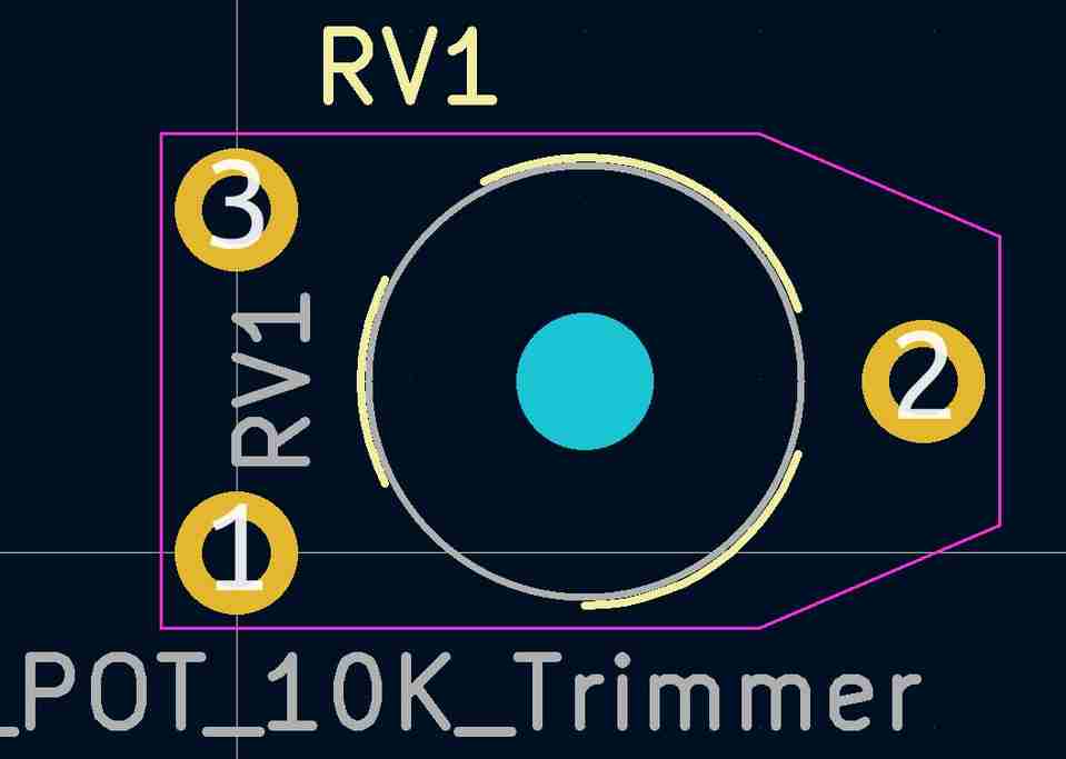
I also needed to use the footprint editor to create a suitable footprint for the potentiometer I am using. I was unable to find any documentation on it so I was stuck with using calipers to measure it by hand. Luckily, the footprint editor was intuitive and easy to adjust. I simply found a footprint that was close to correct, adjusted it, and save it to a new location (since the original was read only). Also, I found a way to turn it 45 degrees by going into properties or double clicking on the footprint.
Milling and stuffing the board seemed to go off nearly without a hitch. I did have one ripped trace between the supply voltage and physical pin 1 of the 1614 chip. Luckily I was able to repair it with a mountain of solder. The custom footprint for the potentiometer worked relatively well, but in the future I might make the holes slightly larger since the fit was very tight. Adding the FTDI interface seems to work as expected. Lastly, the inputs/outputs board had an issue that the regulator was outputting 4.2 V where 3.3V was expected. It seems that I had likely used a 5V regulator by accident. Having identified a 3.3V regulator for this go around, this issue should be resolved. Along with that, the 3.3 V regulator suggested a 0.1 uF capacitor and a 100 uF capacitor whereas previously 2 x 100 uF capacitors had been used. Here is the milled and stuffed board.
However, it is giving me some puzzling results.
The fact that the old IO board code works, tells me that strange phenomena is likely due to an issue in my code. Hopefully something simple. Even still, The user interface/application works, so I am going to call it done for interface/applications week and return to debugging this behavior later on as work towards ANC5 and my final project. This delay will be essential to getting noise cancelation to occur in the inner ear, so I am confident I will eventually get it working.
Circling back, I was able to get the delay working with the IO board and succesfully delaying the audio. In hindsight, the primary issue seemed to be that the Arduino code analogRead() clashes with the bare metal commands I had setup earlier using the chips ADC. For now, this example was created using only the arduino commands. Here are the results,
Eventually, I was able to transition back to the bare metal commands and also able to vastly simplifed the code. Here were the noise cancelation results I then achieved.
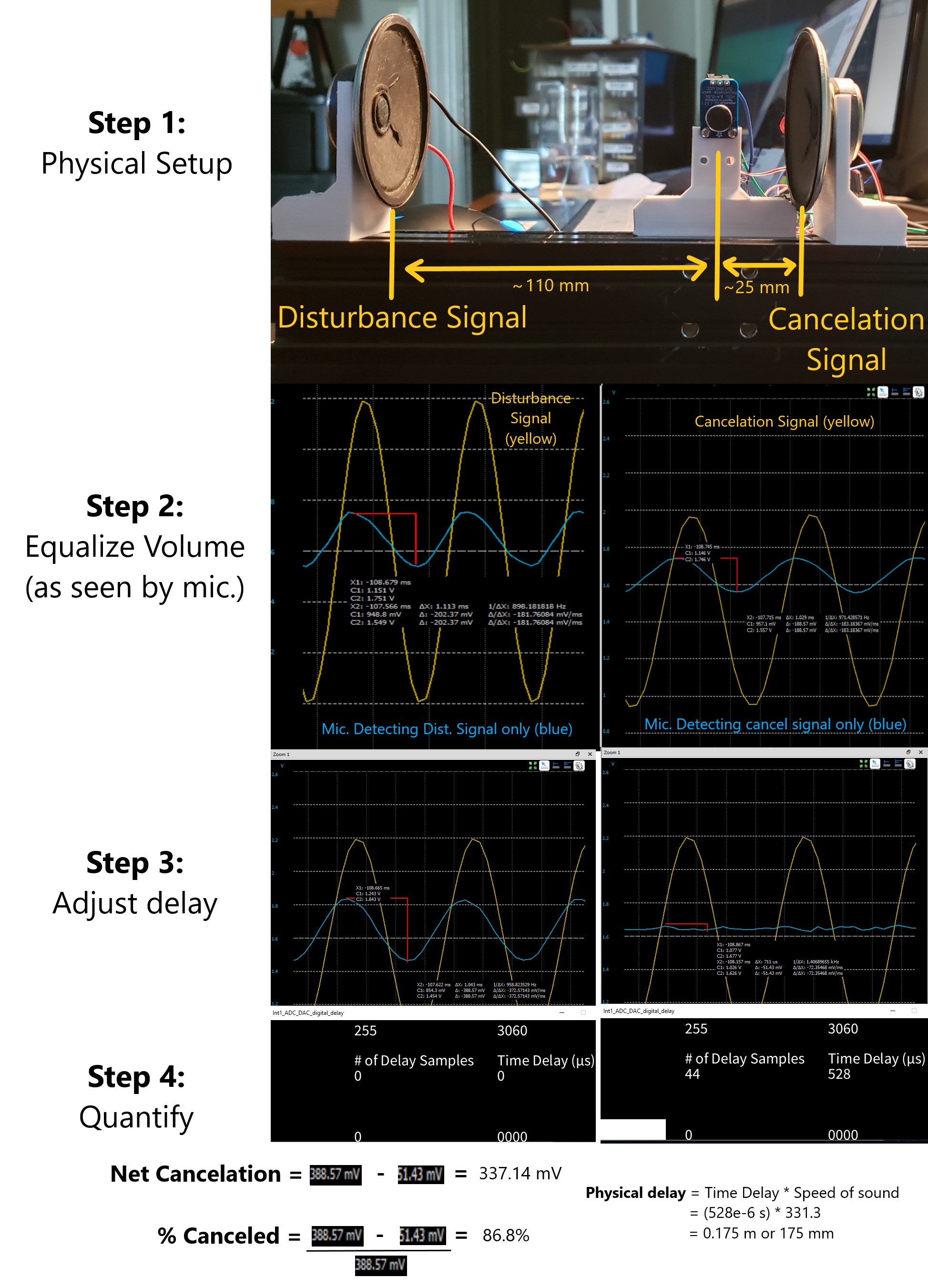
These results are discussed further on my final project page here.
Link to Group work
For this week, our group compared a few different options for creating user interfaces here. I learned that with tools like Processing, creating a user interface can be surprisingly easy and intuitive. Even more complex tools such as Python seem to interface with the Arduino IDE quite easily. With this in mind, I will not hesitate to create bare-bones UI’s for my projects in the future. I can imagine these being useful for things such as product quality testing rigs, household arduino projects, and future studies. Processing feels like a whole world of possibilities waiting to be opened up.
- I didn’t know what I didn’t know about application programming. What a deep subject.
- Simple user interfaces are suprisingly easy and intuitive to create. Nothing to be afraid of.
- Always check to make sure I’ve used = vs. == correctly in code.
- FTDI is a good longterm solution to talk Serial between ATTINY chips and the computer
- Footprint editor in KiCAD is easy to access and implement.
- Make sure to choose the right regulator.
Note: All design files and images can be accessed in my git repository found here.
All works shared on this site 'A Fab Academy Journey with Charlie Horvath' by Charles W. Horvath are licensed under Attribution-NonCommercial-ShareAlike 4.0 International![]()
![]()
![]()
![]()