Week 07: Computer controlled machining
Goals for Computer controlled machining
- Create a piece of furniture I can be proud of
- Don’t use any fasteners or glue (only wood)
- Minimize the number of total components
- ~ Include flexible curved surfaces ~
- Create a scale model for G.I. Joe before going big
~ are stretch goals ~
Rocking Chair
Conception
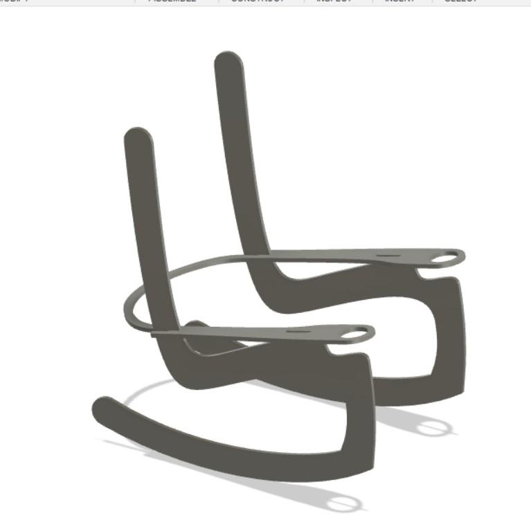
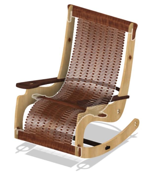
Seeing that my background is in the CNC industry, I feel an added pressure to create something great this week. Originally, I was at a loss for what to create. The idea of a simple table or desk bored me. After going back and forth through a few ideas, I settled on a rocking chair. This would be an interesting shape that would allow me to fufill the extra credit portions of the assignment and push the limits of my design for CNC skills. Plus, a very cool form began to take shape in my mind.
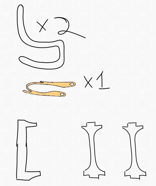
The two side frames can be all one piece, which makes for a cool floating chair affect. Then a few cross members connect them. Then the arm-rest serves 3 critical purposes:
- Structure and connection of side frames
- Arm-rest and drink holders
- Potentially lumbar support.
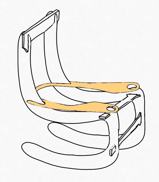
Ok, so we’re down to 6 components, not bad.
But we’re missing something of course. What do you sit on? This is where I fell in love with the idea.
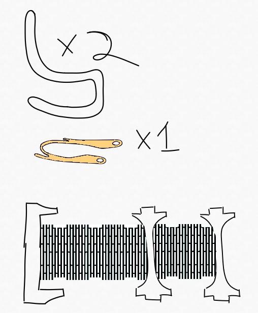
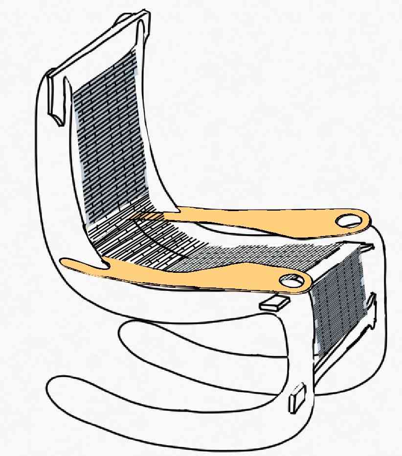
By connecting the cross-members via living hinges, I can create a flexible fabric-like surface for the user to sit on while reducing the total number of components from 6 to 4. This will be advantageous since I found out during week 3, that design for assembly becomes a nightmare when the number of components grows large.
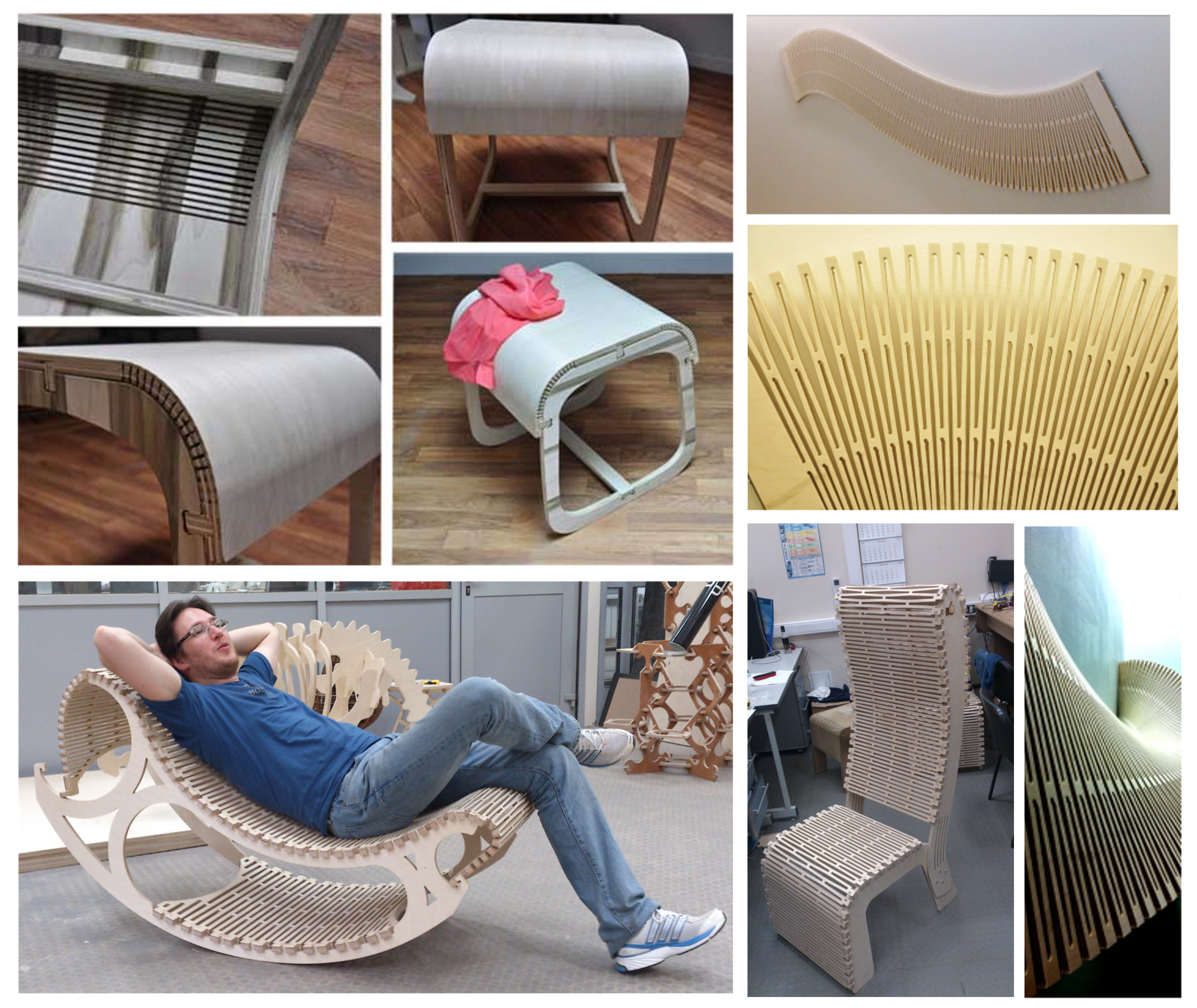
Looks deceivingly easy, but I can’t trick myself into thinking the living hinge portion will be easy. For this, I will be exploring the great work that has come before me such as these examples shared by Neil and that of my mentor Terence Fagan, for this cool bike rack. Full-disclosure, he is also my grader… Hey Terence!
Here are Neil’s examples of flexural plywood.
3D Modeling in Fusion
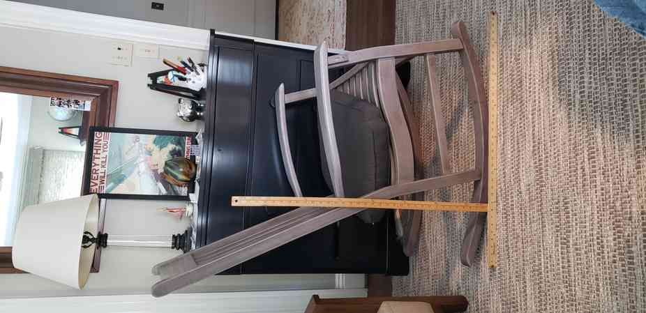
For a scale reference, I will be using my families beloved porch rocker.
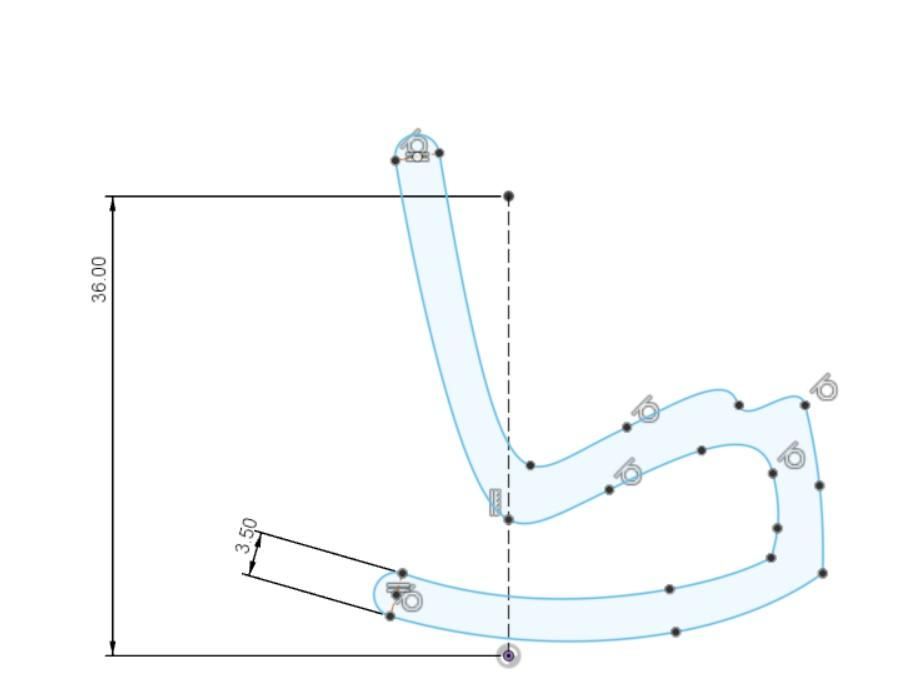
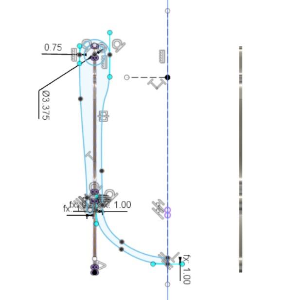
The base Frame pieces and arm-rest came together without too much difficulty.
But then it was time to move on to the crux of it… making a flexible plywood piece.
I started by watching some tutorials.
- Living Hinge Model Fusion 360 Tutorial - Bend Plywood with Laser Cutter
- How to Create “Flexible” Plywood (Kerfing)
- Found this great Kerfing calculator, but unfortunately refers to the other style kerfing
Since the 2nd video uses 0.5 ply, I will simply start with his kerfing parameters and adjust as needed. Then I just jumped right into it.
A trick I learned in the first video is that you can design the component as a sheet metal piece, unfold it, pattern as needed and then refold it. So I created a sweeped feature between the two planks, converted it to a “sheet metal piece” and unfolded it.
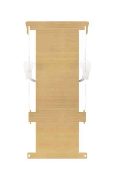
Then I added the pattern recommended in the 2nd video.
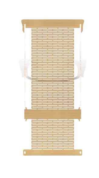
And then I refolded it and Fusion yielded these impressive results.
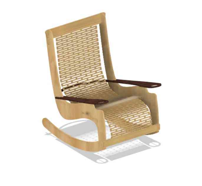
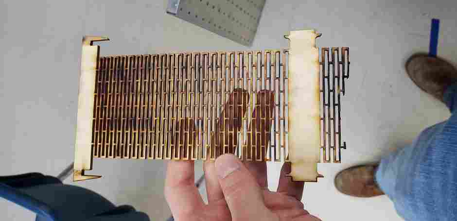
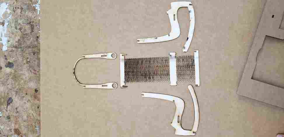
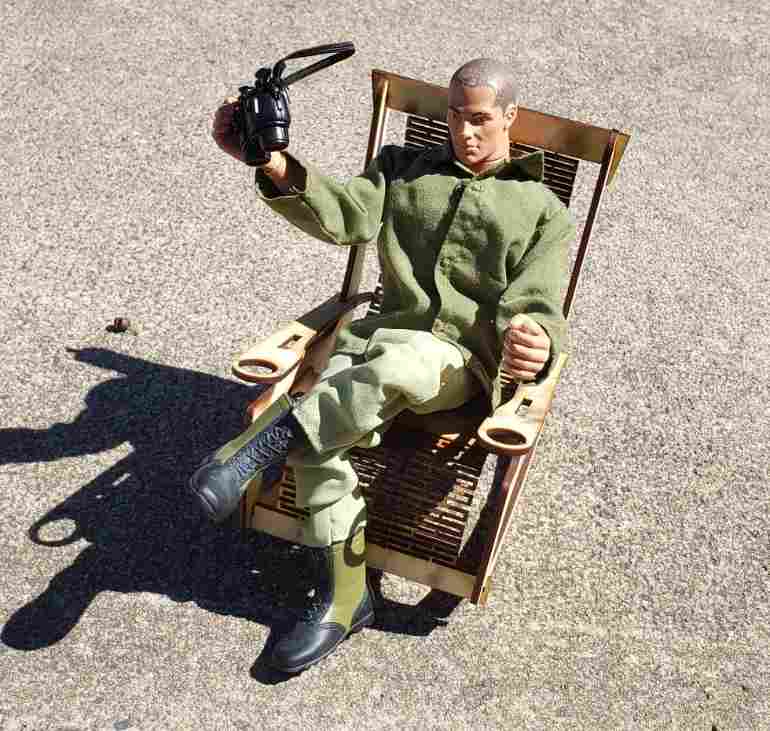
Scale Model for Joe
Next came time to make a scale model. This helped me check the proportions, joints, assemblibility(?), and general design. I wanted to make a 1/6th scale model for G.I. Joe. The only difficulty here was that we only have a few different thicknesses of wood. The best option for the scale model was clearly 1/8th” plywood (3 mm thick), which is about 1/4th the thickness that the model had been originally designed for. Luckily, the model is built parametrically, so I was able to scale the form down 1:6 while only scaling the thickness 1:4.
Note, the first hinge part came off of the laser burnt up and broken. I suspect this is because it cut the outline first, which drops the part down and out of focus for the other cuts. In successive prints, I checked a box that seemed like it would force it to make the cuts “inside-out”. However, this did not work as intended and it still cut the outline first. In any event, I got must have gotten lucky this round because the parts came off pristine.
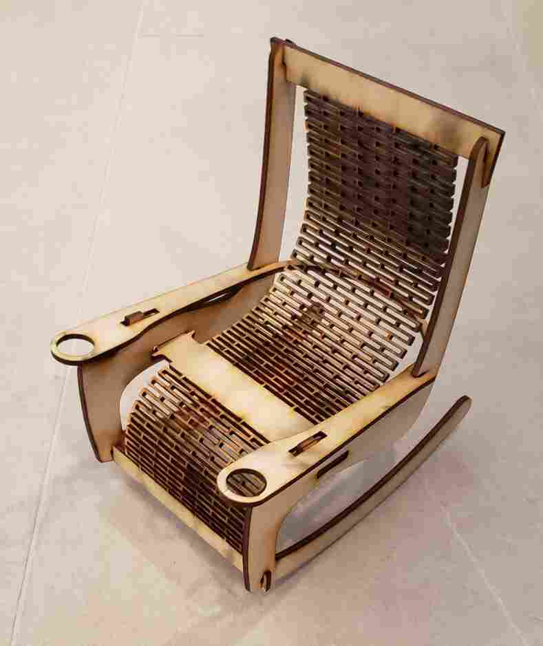
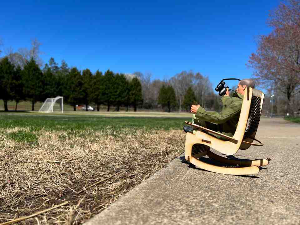
I think Joe agrees : )
As happy as I was with this scale model, I was also able to learn a lot from it!
- Cupholders are too far forward
- the armrest needs a flatter, less curvy section to connect with
- The mat/hinge part works really well! But of course it could use a few tweaks
- The back section could use a little less slack
- The foot section could use a little more slack
- The middle joint needs to be revisited
- 0.5” thick wood may be too thin for the rocker frames. Not much contact with ground
- The rocker frames may benefit from an additional cross-member, to keep them from wedging apart
- I’m starting to think this thing actually has a chance at working!
Below is the new design I implemented for the cross-member, with inspiration from the radial-interlocking-joints found here:
This is one of the joints I will test in the next section.
I also took the time to hone in the armrest joint and animate it:
The next step is to run a test piece on the CNC at regular scale that will allow be to test the flex, joints, fits, etc.
Test Piece on CNC
I quickly chopped up the full-scale model to test these many things at once. I found a suitable 20.75” x 28.75” x 0.75” piece to run this test. I was skeptical that 0.75” would flex as intended, but then again that is largely the point of this test. Additionally, I pulled out some of the joints to test them.
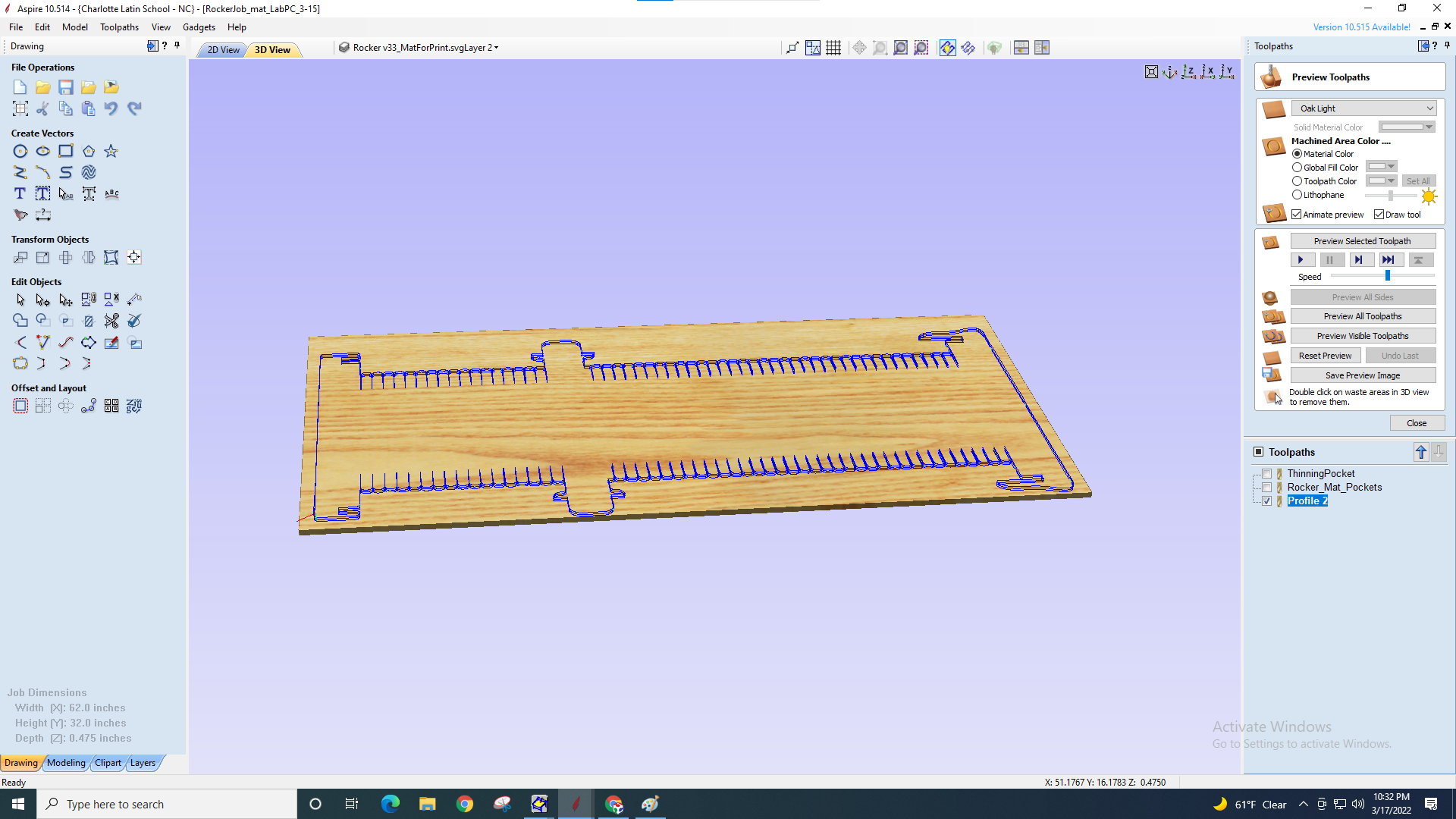
I was originally setting up on the desktop shopbot, until seeing that the pocketing alone would take 2.5 hours. Tom then pointed out the difference in feedrate between the desktop (40 mm/s) and the alpha (250 mm/s). Once I moved the job over to the alpha, the same estimate read 32 minutes. Important note: I nearly made a critical error when switching between machines. That is, the axis of the two different machines are oriented differently in the room. So if I’m looking at the North wall, I am looking at the X-axis for the desktop machine but the Y-axis for the Alpha. This error was caught by a classmate during the air-cutting on the Alpha. So I had to adjust the orientation of my work in aspire before proceeding.
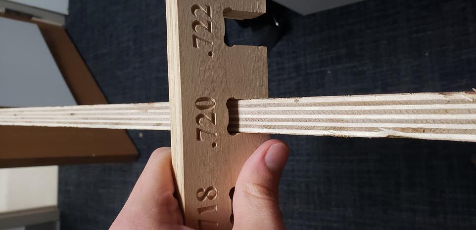
The other main thing I found in aspire was that the fillet/dogbone tool was finicky. It required that I join the lines before adding fillets. This was time-consuming for the pockets, so I will be adding these fillets in fusion going forward. I also suspect the issue of unjoined vectors is related to the DXF format. In the future I will try SVG. As for Dogbones, I will leave these to Aspire since these would be less straight-forward to add in Fusion. Before exporting to aspire, the last thing I did was adjust the fit of my joints based on this comb for 0.75” plywood I was using. Meaning, I made my slots 0.72” wide.
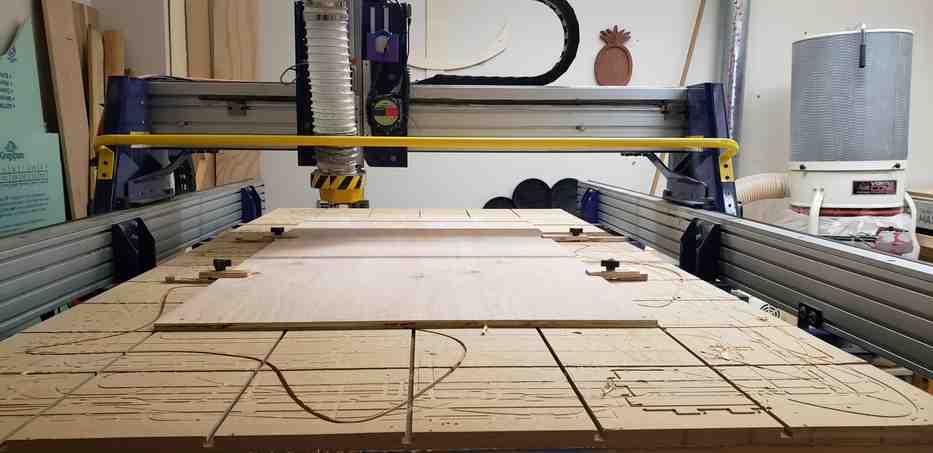
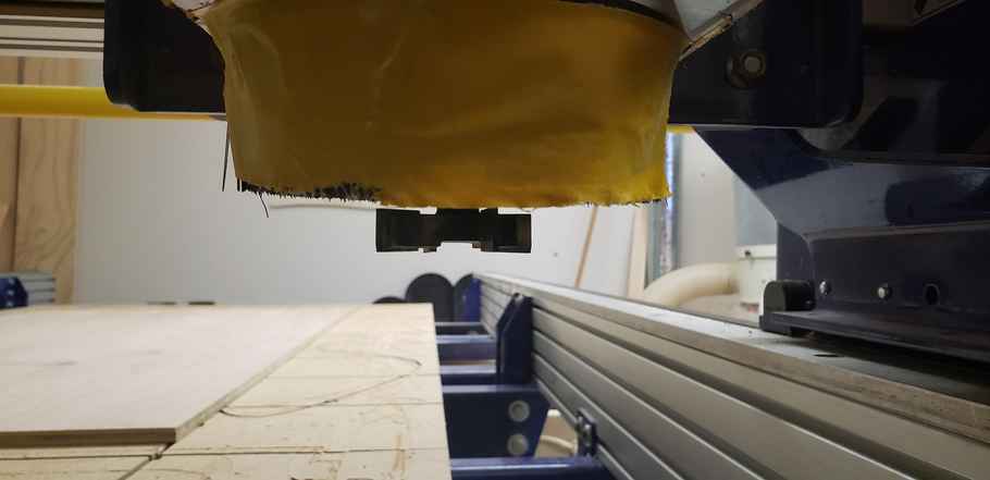
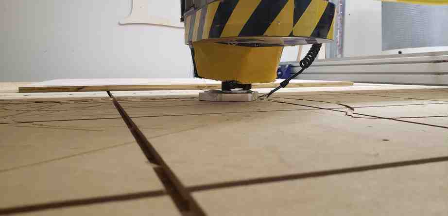
For fixturing, I used the 4 aluminum toe-clamps and about 4 screws strategically placed around the board. However note, due to the height of these toe-clamps, the job needed to be paused at several points so they could be repositioned. Other times, it got a little close for comfort due to their height…
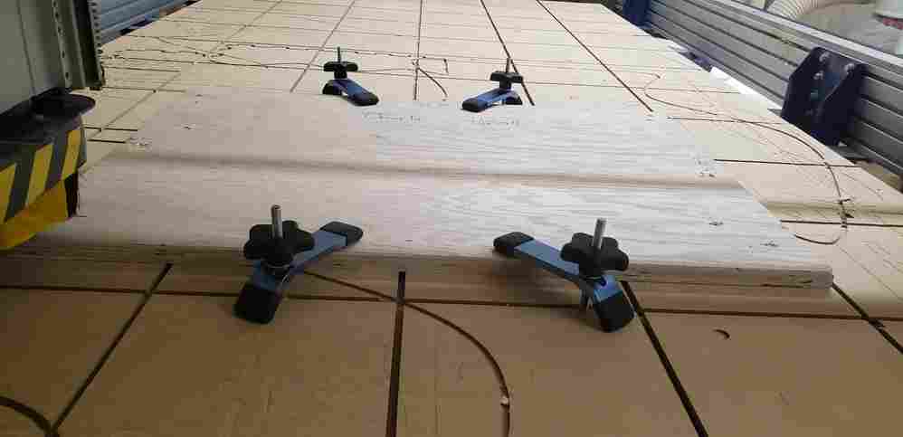
As they sometimes say in industry, “clearance is clearance”.
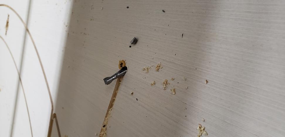
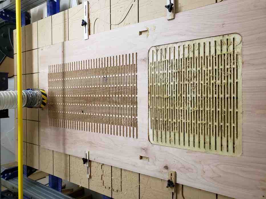
The only other issue I ran into with this run occured when pausing the machine. pausing occurred when we happened to also switch the spindle off via the key. This time, the bit slightly gauged the material between two of the slots. One way or another, the spindle slightly forgot where it was in its routine. Luckily the rest of the job proceeded without issue. To avoid this issue in the future, I will try to limit pausing mid-job, and especially try to limit the need to switch the spindle off when I do pause, since this is the prime suspect.
The first major conclusion of this test run was that the flexural piece would not bend enough to be useful. I need this piece to bend about 90 degrees and I was getting 45 at best.
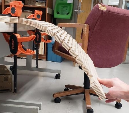
Also as a result of these test cuts, a few other things are clear.
- Living hinge needs to be revisited. 0.75” ply does not bend nearly enough with this pattern.
- Increase # of slots, increase ratio of the size of slots:solid pieces, use thinner stock.
- Redesign of seat joint is overengineered and doesn’t fit. Revert this.
- Cross-member radial-interlocking-joint design is good if I tighten up the depth of the cutout.
Producing the Final Design
I realized the main joint could be majorly simplified because it should be self-locking due to the spring forces and counteracting reaction forces.
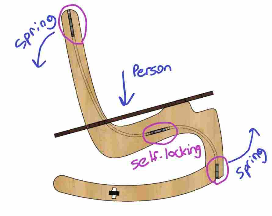
Here is hopefully the final design. It uses 0.75” pieces for everything except for the flexible mat, which will now be made from 0.5” ply, with 0.25” x 4.1875” slots on a 0.1875” pitch. Hopefully this will offer the bend I am needing. If not, I suspect I will be able to use water techniques to get any remaining bend out of the wood. I am also planning to talk to Terence Fagan before cutting these exact parameters.
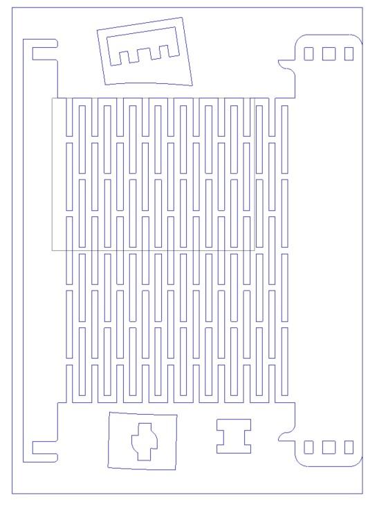
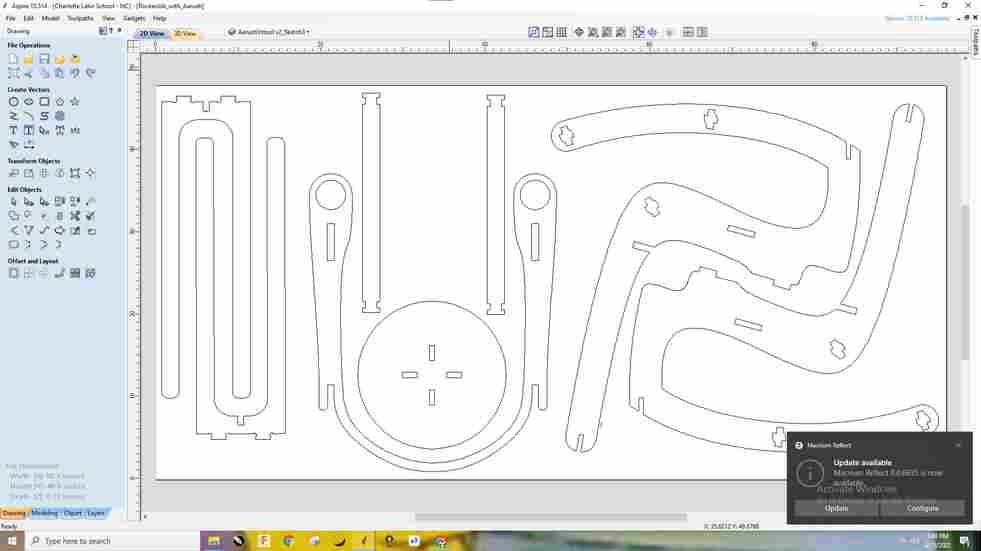
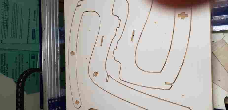
A classmate Aarush and I decided to run our 0.75” pieces together to save machine time and look over eachothers’ shoulders. Here is the work we did to nest the frame pieces in aspire.
Issues
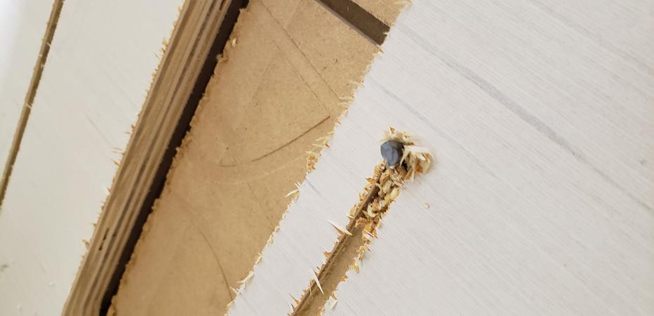
Unfortunately, we had some issues while running this job. First, midway through a cut, a bit got pulled further into the material and began to make a nearly full-depth 0.75” cut. To stop this, we turned the large red switch on the side of the machine. Unfortunately, unlike a true kill-switch, this switch only stopped the spindle and not the axis. This promptly sheared the 0.25” bit. The prime suspects for this issue were that the collet was undertightened around the bit and the workpiece may have been chattering enough to pull the tool from the collet. This chatter may have been caused by using shallow tabs 0.125” that broke throughout the run. Midway through, we switched to 0.25” tall tabs and the issue was negated.
Later on, unfortunately broke a 2nd bit with a direct hit on a metal screw. However, Aarush made the good point to Neil that these issues may have been compounding, since we had added extra screws to the job after experiencing the chatter issue earlier described.
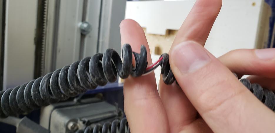
Down to our last 0.25” bit, we had one final issue. To touch off the new bit, we we’re forced to touch off near the middle of the table where some of the machine surface was exposed. We had not placed the Z-locator back into its sleeve before sending the machine home. This dragged the chord into the Y-axis of the machine. Once untangled, we noticed the outer-shielding had been stripped off but the inner-wires were intact. Prime suspect for this error, getting sloppy after many hours at the machine. We can do better!
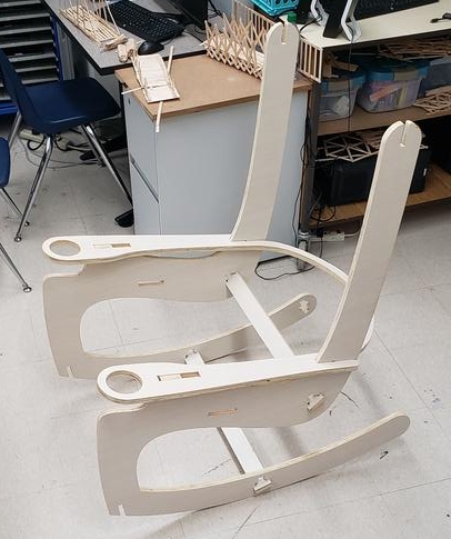
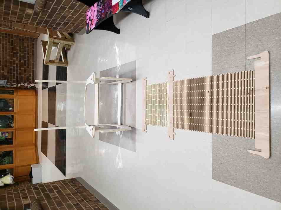
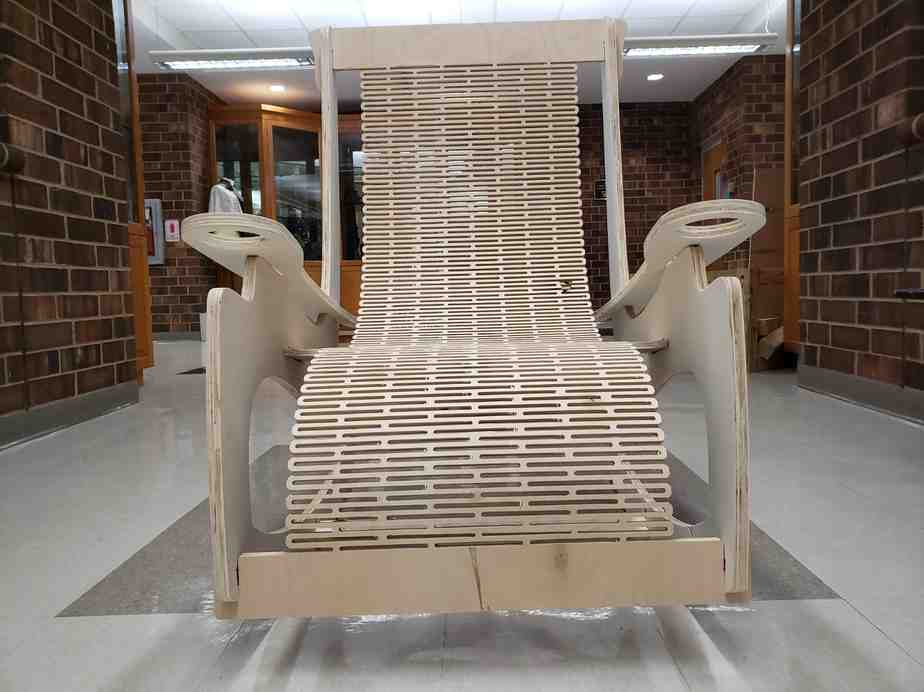
Assembling the Frame
Not much later, we completed the 0.75” job. I removed the tabs and sanded down the parts.
The fits were all on the loose side due, but satisfactory nonetheless. No glue needed!! I believe the final mat part will drastically increase the stability of the overall construction.
Machining the mat (living hinge)
And so it was time to run the mat. Since the test part, I had spoken with Terence and implemented the following changes to the file:
- 0.75” ply - > 0.5” ply
- 0.375” width slots - > 0.25” width slots
- 0.375” solid sections - > 0.1875” solid sections
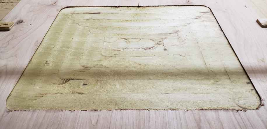
And to be extra careful, I decided to face mill some of the material on the backside of the foot section of the mat. This section will require the tightest bend of curvature. Terence and I agreed that reducing the thickness of this section would allow for a tighter bend of curvature. He also had the useful analogy to think of the piece as a sort of chain rather than a solid piece under bending.
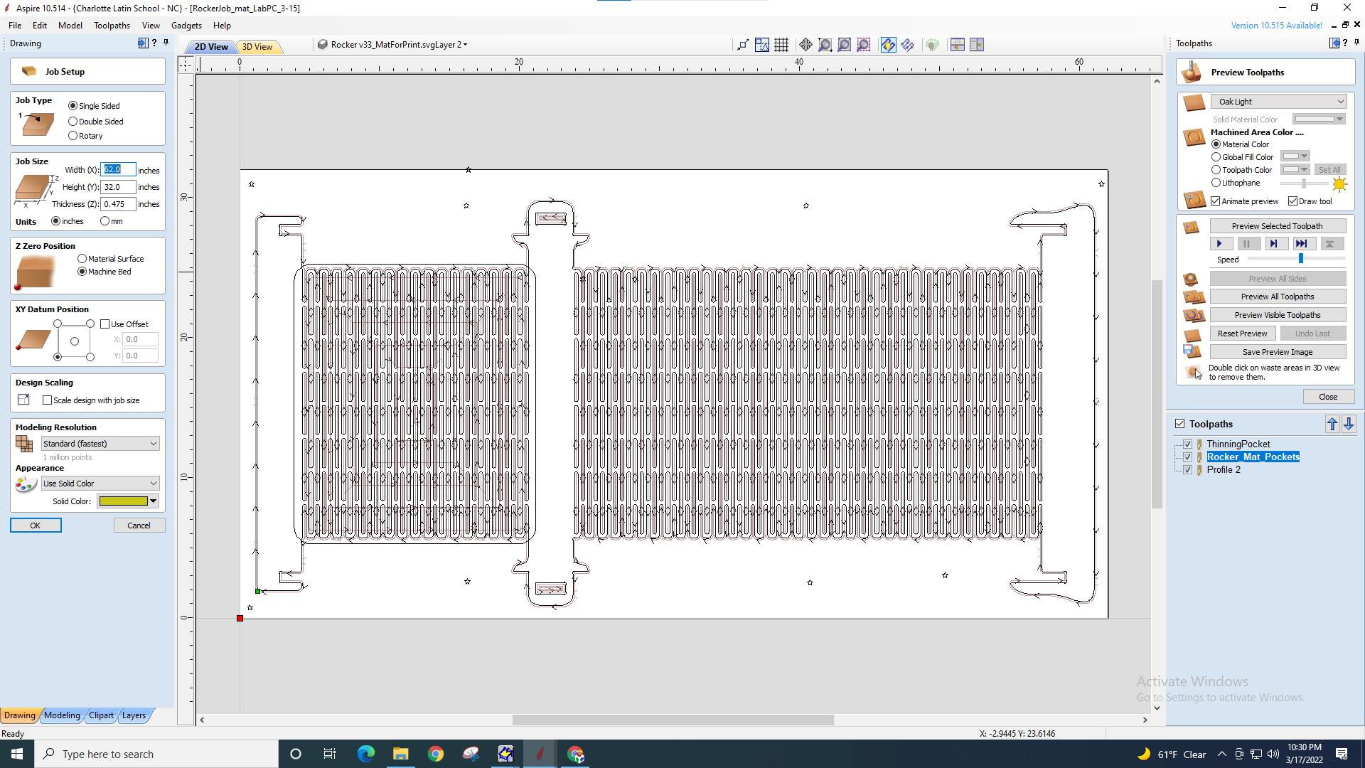
With all of these changes in mind, I was confident the piece would perform as desired. Here is the final Aspire file and fixturing. On account of the aforementioned SPONTANEOUS EXPLODING CARBIDE SHRAPNEL, I have decided I will be marking all fixturing elements with little star symbols in Aspire.
For the facing pass, I decided to use our labs 2” x 1/2” x 1/2” shank key cutter. Our team had preloaded feeds/speeds for this tool, just as with most of our tools.
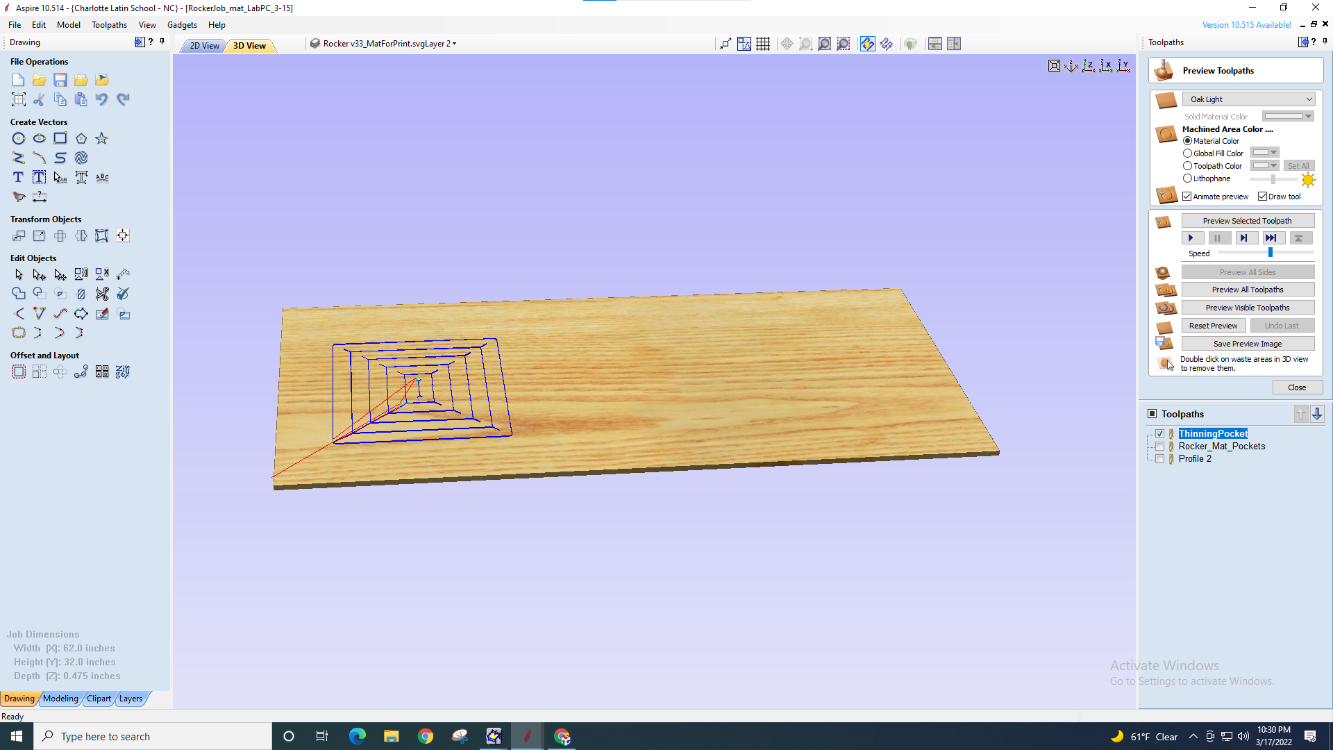
I encountered a slight issue with touching this tool off since the z-locator pad has a 2” diameter touch zone and the tool itself is 2” diameter. This was alleviated by a careful disassembly/reassembly of the pad.
The facing pass went off without any major hitches. I did notice some scorch marks from this tool. I believe this is a sign that the rpm is too high compared to the feed rate, and the tool is left to dwell on spots for longer than necissary. A quick look back at the settings and this is unsuprising since we are running this tool at 18,000 rpm and 100 mm/s. I also heeded Neil’s advice to be on watch for any further smell of smoke, which could be a bad sign that the dust collector is on fire.
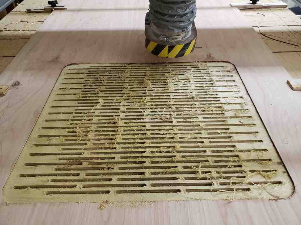
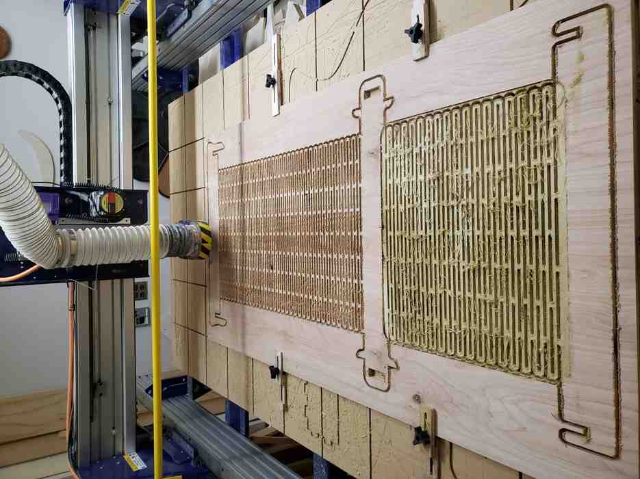
On to the bulk of it, the pockets.
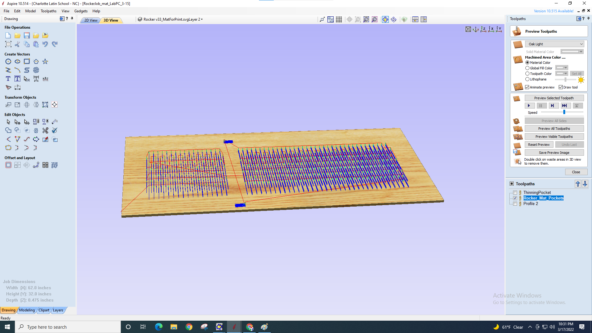
Aspire had a 3 hour time estimate. Somehow this run took just under 2 hours. Unsure where the disparity arose (perhaps from transferring file between to computers?) but whatever the case, no complaints.
And finally, the outer profile.
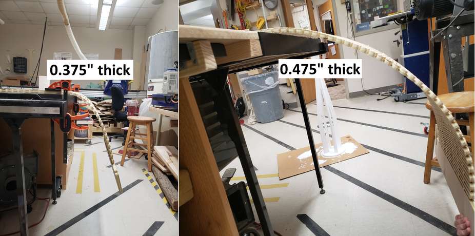
And now for an underappreciated part of the process, post-processing.
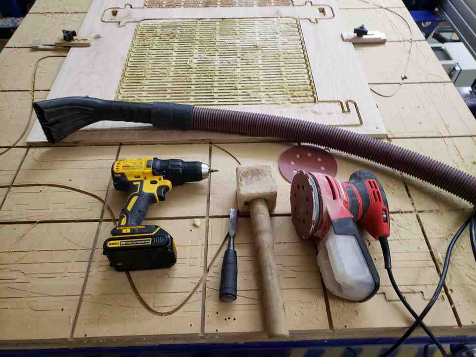
It was immediately clear that removing 0.1” from the back-portion of the foot mat did make a difference. See unscientific comparison of their bend-curvature (bendature?) below.
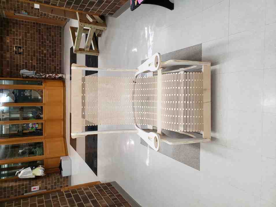
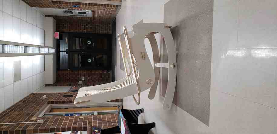
Final Assembly
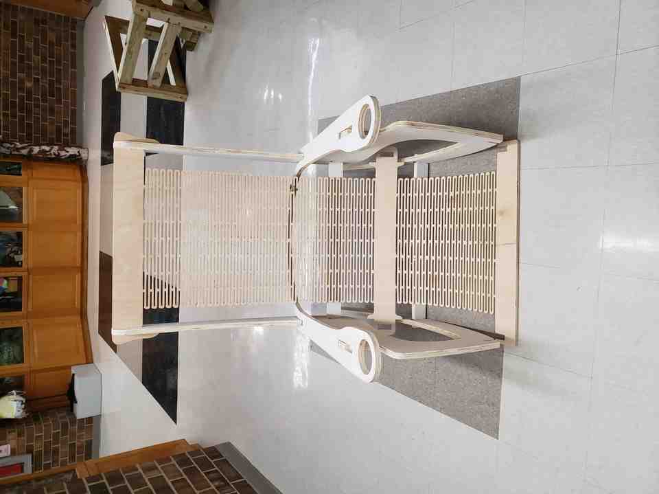
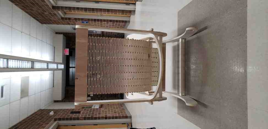
Not pictured because my phone died - one of the most careful but satisfying sits of my life.
It works! No screws/glue required. Which leads me to the system requirements.
| Minimum System Requirements | Recommended System Requirements |
|---|---|
| ❌ - Screws | ✅- Screws (and pilot holes) |
| ❌ - Glue | ❌ - Glue |
Future Plans: Finish the rocker with a weather resistant finish, add screws, take a hero shot, and smile everytime I look at it.
Group Project - Characterize the CNC machine
Documentation on our groups efforts to characterize and train on the shopbot Alpha can be found here. My contribution was to help design the alignment and toolpath test pieces to characterize these aspects of the machine. Additionally, I helped the team understand and run the runout tests.
- Sprial development saved me a lot of time, headaches and wood in this case.
- Good CAD practices pay-off 10-fold when it comes time to make changes. (e.g. parametric joints)
- Cheap plywood thickness varies across the sheet. Hard to design joints for.
- No need to account for Kerf if we simply use the joint combs
- SVG add-in for Fusion was worth its weight in gold (and the $14.99), to completely avoid .DXF
- Create fillets inside of Fusion
- As far as I can tell, a living hinges bendature depends on 2 main variables: thickness and the ratio of air:wood.
- The self-locking concept was a good one, but did not account for gravity. In hindsight, the force of gravity was greater than the spring force for the thinner mat. As such, perhaps the thinning was overkill and reduced the spring force.
- Sprial development differs from iteration because instead of creating 3 full-prototypes, I only had to create 1 & 1/6 prototypes and some test cuts. I see the value. Also, it could be thought of as a 3D upward spiral towards something great.
- Always uncheck offset
- Dogbone tool works well. Normal fillets should be done in CAD
- Speeds/feeds are only accurate on PC that controls the machine
- Speeds/feeds are much faster for Alpha over Desktop size
- SVG did much better than DXF
- Grouping is for moving elements together, joining is for turning them into one vector.
- 0.25” tabs may be preferable to 0.125” when using the whole machine bed, which isn’t flat
- Cutting precision interior features as pockets rather than contours will take longer but require less post-processing to clean-up.
- Always make sure aspire axis match the machine, and the origin agrees.
- Aspire job time estimates are not always accurate.
- Add star symbols to denote fixturing elements. This might deserve to be in the offical workflow.
- Aspire toolpath options are great but limited. In my mind, I had a much more efficient path the tool could take that would have potentially cut the cycle time in half.
- In the future, I could consider splitting such a run into 3 layers and machining the first layer for every feature first, followed by the second layer, etc. This is traditionally less efficient, but could avoid the unnecissary travel-back moves I was running into in this case.
- Always be sure to use the right size collet and don’t be gentle when tightening
- The red switch may not be a reliable E-stop. Spindle stopped but axis’ kept moving
- Consider using plastic screws, be very careful about screw placements
- Always say outloud what I am doing next
- Machine bed is not perfectly flat.
- Machine does not like to sit on the prox. sensors when you tell it to home on prox. censors
- If tabs start breaking mid-job, workpieces may chatter.
- Chatter will break bits. Watchout for it.
- I almost pulled an all-nighter to finish the mat and show Neil in the morning. For safety reasons, I am glad I did not.
- Fewer screws/fixturing elements are needed than I first imagined.
- Facemill left burn marks. Increase ratio of Feed:Speed.
- I need to think about getting one of these things!!
Note: All design files and images can be accessed in my git repository found here.
All works shared on this site 'A Fab Academy Journey with Charlie Horvath' by Charles W. Horvath are licensed under Attribution-NonCommercial-ShareAlike 4.0 International![]()
![]()
![]()
![]()