Week 8: Embedded programming
Goals for Embedded programming
- Program Blinkie-Fadie to toggle blinking and fading with the press of a button
- Browse the ATTINY 412 datasheet and document
- Look into other tutorials for the ATTINY 412
- ~ Program Blinkie-Fadie to do something else
~ are stretch goals ~
Programming Blinkie-Fadie
Following Adam’s guide for programming a target board with our SAMD chip, I programmed the chip using a simply blink program.
Then it was time to turn to my new code, the mashup between Blinkie and Fadie, Blinkie-Fadie. I went back to TinkerCad to pull this code into the Arduino IDE. I left the serial lines commented out. I confirmed with Tom, serial is not needed when working with a 412 chip since it has an internal clock. Moment of truth,
Bare Metal Programming
Tom’s Arduino Example
Following Tom’s lecture here and the youtube tutorial here, I was able to make an LED blink using bare metal programming techniques. See code below, and the comments explaining what I did.
void setup()
{
  DDRB = 2; //Sets pin PB1 to an output, which is physical pin 9. 2 = 00000010 which controls PB1
}

void loop()
{
  PORTB = 2; // Sets PB1 to HIGH and the rest of PB to LOW
  delay(1000); // Wait for 1000 millisecond(s)
  PORTB = 0; // Sets all PB pins to LOW
  delay(100); // Wait for 1000 millisecond(s)
}
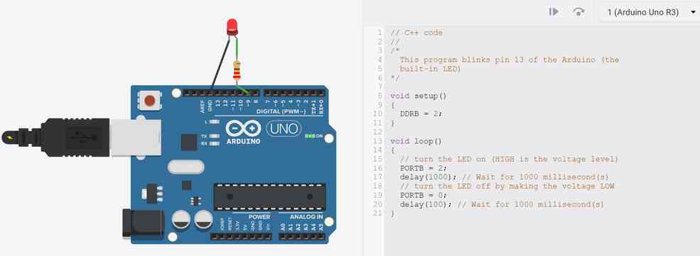
This seemed to work!
Programming Blinkie-Fadie with Bare Metal Techniques
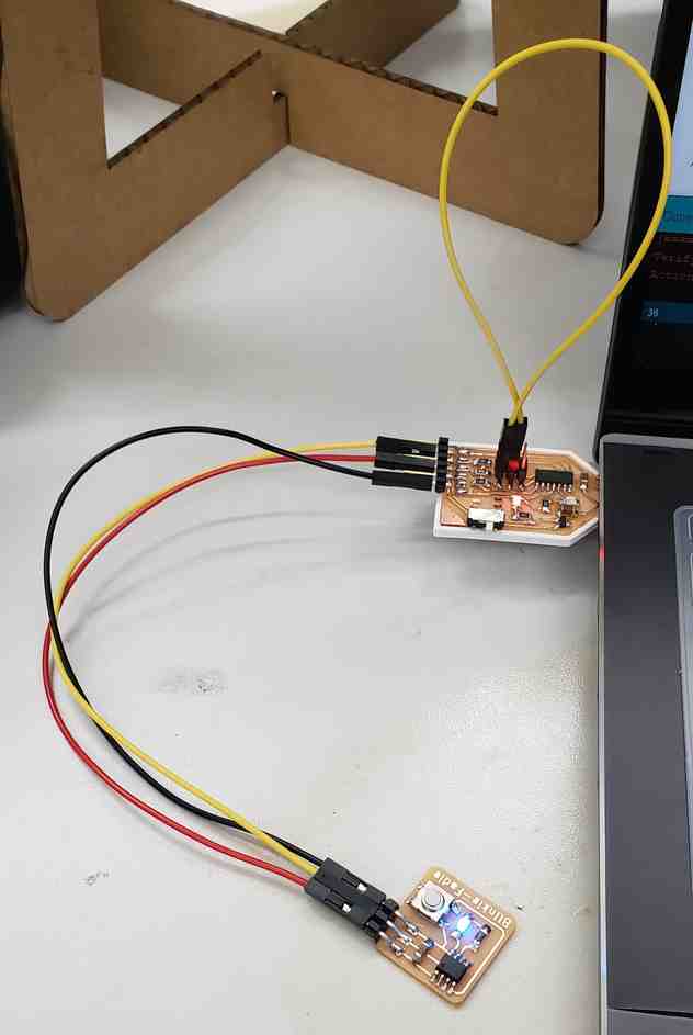
So I turned my attention back to my Blinkie-Fadie board, hoping to also program it with some level of bare metal techniques. However, this board will have many differences from the Ardunio example. Here are the few I have identified as important:
- Chip is ATTINY 412 instead of ATMEGA328
- PINS are labeled as PA instead of PB e.g. My output pin is PA3 instead of PB1
- My blinkie-fadie code uses analogWrite commands, which may require other bare metal techniques to supplement
- After digging through the ATTINY datasheet, it seems that the chip works in a similar manner, but requires slightly different commands to accomplish e.g. “PORTA.DIR” instead of “DDRA”
- Analogwrite did not seem to work once I started to program with baremetal commands. I will need to find another way to do PWM.
A few resources that I found helpful during this process.
- All of the resources Tom shared, including this presentation
- ATTINY 412 Datasheet
- Getting Started with GPIO Tutorial
- 2020 Student Wan-Ting Hsieh’s experience with Bare Metal Programming
- 2021 Student Loes SchakenBos’ software PWM example
This page from the datasheet proved especially useful.
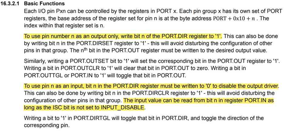
So first I wanted to replace the HIGH & LOW blinking codes with bare-metal commands. To do this, I needed to both set the output pin up differently and write the output differently. As such, the following code was replaced accordingly.
// LED SETUP
// pinMode(OutPin, OUTPUT); // gets replaced by
PORTA.DIRSET = PIN3_bm;

...

// LED ON
// analogWrite(OutPin, 255); // gets replaced by
PORTA.OUT |= PIN3_bm;

...

// LED OFF
// analogWrite(OutPin, 0); // gets replaced by
PORTA.OUT &= PIN3_bm;
This seemed to work without much fuss. Note that originally I had attempted to use the _DDRA__ command to set all the pins at once, but upon reading the datasheet I found this was not the best way. Upon reading others experiences, I settled on setting up the specific pin with PORTA.DIRSET.
Then I wanted to change the input detection over to bare-metal as well.
// Input Setup
//pinMode(swPin, INPUT_PULLUP); // gets replaced by
PORTA.DIRCLR = PIN1_bm;  // Specifically sets digital pin 2, which is PA1 and physical pin 4, to an input pin.
PORTA.PIN1CTRL = PORT_PULLUPEN_bm; // activates an internal pullup resistor to be used with Pin1.

...

// Reading input
// int sensorVal = digitalRead(swPin); // gets replaced by
int sensorVal = PORTA.IN & PIN1_bm;
For awhile, setting up this input method was not working. After reading through the getting started with GPIO tutorial, I realized I needed to enable the internal pullup resistor for this input pin, similar to how I had done so with the original digital command pinMode(swPin, INPUT_PULLUP). This got the input working. If you take a look at the source code, you will find that I strategically placed additional sensorVal assignments throughout my loops to ensure that the program is quickly responsive to user input and does not get stuck finishing loops. I also replaced my delay commands with something that seemed more metal.
//Required libraries (not previously required)
#include <avr/io.h>
#include <util/delay.h>

// delay(100); // gets replaced by
_delay_ms(1000);
At this point, I was able to get the program to switch between two different blink-rates at the press of the button, but anytime I tried to have it fade, the analogWrite() command caused the fade loop to get stuck. No worries, the goal is to replace this with bare-metal commands anyhow! At this point, I discovered Loes SchakenBos’ code for creating the PWM effect using software rather than analog hardware. This would allow me to use the same bare metal output commands as I had for the blink, i.e. PORTA.OUT |= PIN3_bm; and simply vary the time that the LED is on for. As such, I copied his for loops for fading up and fading down and tweaked to my hearts content.
To this end, I am certain there are better ways of creating this PWM affect using bare-metal commands and true analog output. Even still, this was the best way for me to get it working with my limited understanding and in a timely manner.
Here is bare-metal Blinkie-Fadie in action.
Seems pretty metal to me.
Interestingly, the software fade looks much more choppy on video than to the human eye. This is likely due to a fixed refresh rate of the camera and the camera attempting to adjust to rapid changes in light. Perhaps most interestingly, the true analog PWM from my first program did not have this issue.
Overall, this was a worthwhile exercise because it forced me to dig through the datasheet and other resources, looking for a greater understanding of how the 412 chip thinks. My program size ended up actually growing between the first Blinkie-Fadie program (1034 bytes; 25% of the chips flash) and the Blinkie-Fadie-Bare-Metal (1242 bytes; 30% of the chips flash), but I suspect this has more to do with the structure of the loops and length of the program than the commands themselves.
Note, after watching Tom’s in-person lecture on bare metal techniques, I began to realize how inefficient my code was. Not only was I creating an unnecessary variable to check the status of the switch, I was reassigning that variable multiple times throughout the code. Following Tom’s lead, I was able to use a pointer reference instead.
#define swInputPointer *((volatile byte*)0x02) //Critical pointer that points to our input memory.
...
while(swInputPointer == 1) { // If the switch is closed, fade.
This change alone helped me drastically reduce the # of lines of code and. See “blinkie-fadie-Bare-metal-efficient” in my repo. Here was the full compiling output from each of my 3 versions of the program. Suprisingly, the gains between the bare-metal and bare-metal efficient versions we’re suprisingly not that great.
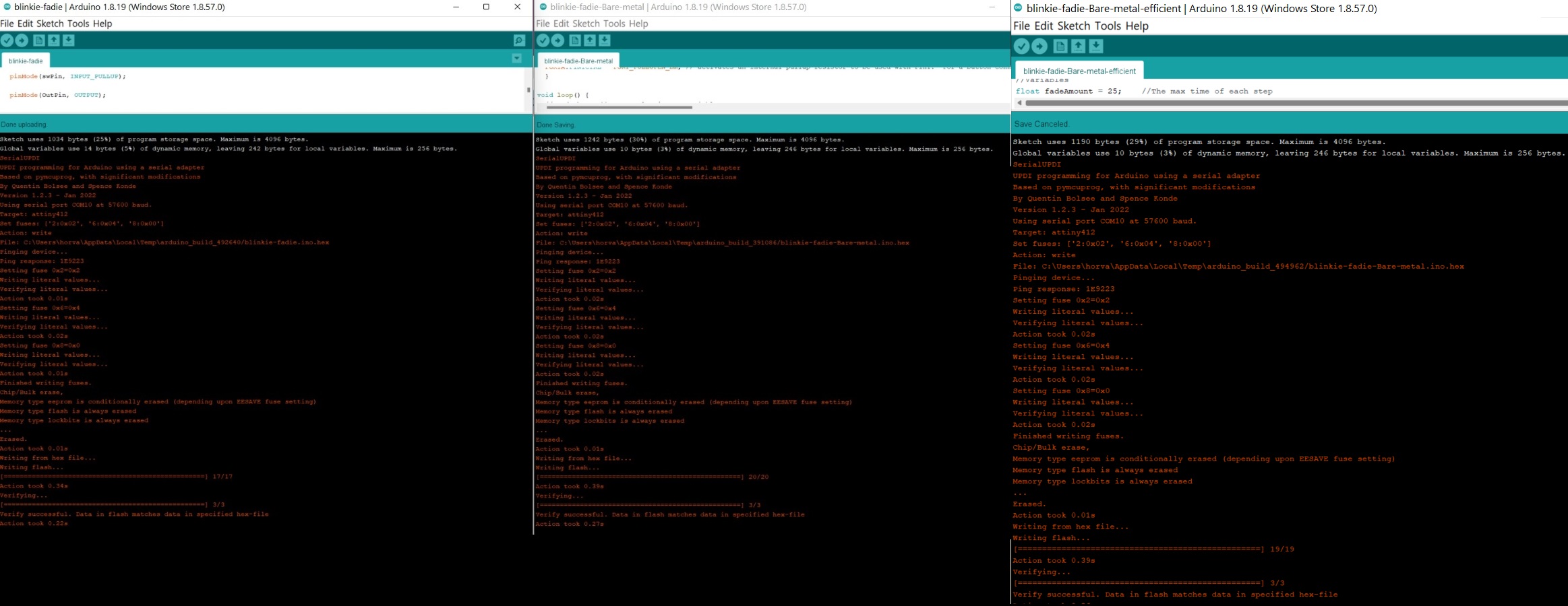
Even still, the third option feels like the most efficient program, I will need to dig deeper if I am to understand why that may technically not be the case.
Reading the ATTINY 412 Datasheet
Truly, because of my limiting understanding coming in, it was hard for me to gather a ton of useful information from this exercise. I was able to gather the most when digging through the datasheet for information when I needed it. In these cases, I was able to have a much clearer understanding of what the text was referencing. For subjects that I had never heard of, I may as well have been reading German. Even still, some random subjects proved to be interesting and insightful such as,
- AVR naming conventions and what 412 stands for
- Physical pins 1 and 8 are reserved solely for VDD and GND respectively, and share no other functions
- Physical pin 6 is the only pin that can handle UDPI. It is also the RESET pin.
- Chip has 4 KB of flash memory for program storage
- Memory is split into Flash (for programs), SRAM (low latency, high speed data access), and EEPROM (firmware settings, or like BIOS on a PC)
- Different peripherals such as GPIO, CPU, VREF, ETC. are stored at different base addresses (hexidecimal) - see Table 7-1.
- Pinout drawing and multiplexing chart seem important
- Board can convert between analog-to-digital (ADC) and digital-to-analog (DAC)
- Power consumption is well documented and potentially easy to calculate
- Junction Temperature is a simple equation
- Chip has internal thermometer and of course, temperature ranges
- Adding a heatsink is an option and also has an equation.
- UPDI is well documented
- Package drawings/tolerances are available.
Link to Group work
For the group assignment, our group compared and contrasted the performance and development workflows for the SAMD11C and the Atmel Mega 328. This comparison can be found here.
- Serial is not needed when working with a 412 chip since it has an internal clock
- Bare metal programming can be more efficient than using C-code. Additionally, it allows you to access the full-capabilities of the chip whereas C-code and the Arduino IDE hide potential options away.
- Each pin has a physical number (1-8), an Atmel # (PAn), and an ardunio # (0-7). No wonder I was confused
- Microprocessor is more powerful but simpler (think PC processor) and needs more supporting chips to run. On the other hand, a microcontroller is what we are using. It has a lot of those supporting functions baked-in.
- A bootloader is a program to load programs. Once we’ve used a programmer to load a bootloader, you can theoretically then program a chip directly.
- Machines don’t understand source code that we write. They understand machine code. A compiler bridges that gap for us.
- Make file is a list of rules that explains how your board reacts to prerequisites. Arduino IDE autogenerates this for us.
- An FPGA is used when you progress past the limits of MCU’s. This allows you to create your own integrated circuit in software. Not something I need to worry about for awhile…
- Pseudo-PWM can be accomplished in software.
- 412 board can convert between analog-to-digital (ADC) and digital-to-analog (DAC)
- See list of topics from reading datasheet above.
Note: All design files and images can be accessed in my git repository found here.
All works shared on this site 'A Fab Academy Journey with Charlie Horvath' by Charles W. Horvath are licensed under Attribution-NonCommercial-ShareAlike 4.0 International![]()
![]()
![]()
![]()