Week 2: Computer Aided design
This week I stretched my knowledge of Computer Aided Design (CAD) by using solidworks, surface modeling tools, corel draw and a Spacemouse peripheral.
Goals for CAD Section
- Use Solidworks instead of more familiar tools
- Understand/demonstrate surface based modeling towards my final project
- Use reference images and models to build a to-scale conceptual model
- Create a smooth flowing and ergonomic shape.
- Make it hollow, to leave room for hypthethical electronic components.
- ~Render the finished concept~
- Understand/demonstrate designing for SLA resin printing
- Learn a 2D program such as corel draw or Concepts
- ~ Understand/demonstrate algorithmic design ~
- ~ Understand/demonstrate generative design ~
- ~ Become accustomed to using SpaceMouse peripheral ~
~ are stretch goals ~
Existing CAD Experience
I’ve used Fusion 360 (F360) extensively. I maintain a personal license for it and use it for personal projects as well as contract work. I took one course in Solidworks (SW) at University, but this was also my first entry into CAD. Additionally, having then put SW down for many years, I would like to use it for this course and become profficient. This video works in the reverse direction as I am, but still proved helpful to understand some of the difference in logic between the two programs. Some noteworthy differences:
- SW assemblies refer to multiple files. SW parts often should be modified individually, then assembled. This will be a big challenge to my workflow but other workflows are possible such as designing in the context of an assembly
- Some SW files can be incompatible with different versions of SW (2022 vs. 2014)
- Timeline and Browser in F360 are separate but are merged into one to form the feature tree in SW
- Sometimes multiple mates are needed in SW to constrain all d.o.f whereas a Joint in F360 handle all d.o.f (bottom-up vs. top-down)
- F360 might have more mesh/surface tools
- SW allows customizable keyboard shortcuts
- SW sketches get assigned to features, but seem like they can still be reused.
I have only knowledge but no real experience with surface based modeling and generative design. I am also beginning to print with Resin’s for the first time.
I own a Spacemouse, but have not grown accustomed to using it.
Beginning with Solidworks
Following a link I received via email, I began installing Solidworks through the 3Dexperience portal. More specifically, I will be using the “3DEXPERIENCE SOLIDWORKS Proffesional” program, which needs to be opened from a web-browser as far as I can tell.
Upon loading in, the system reccomended running a diagnostics check.
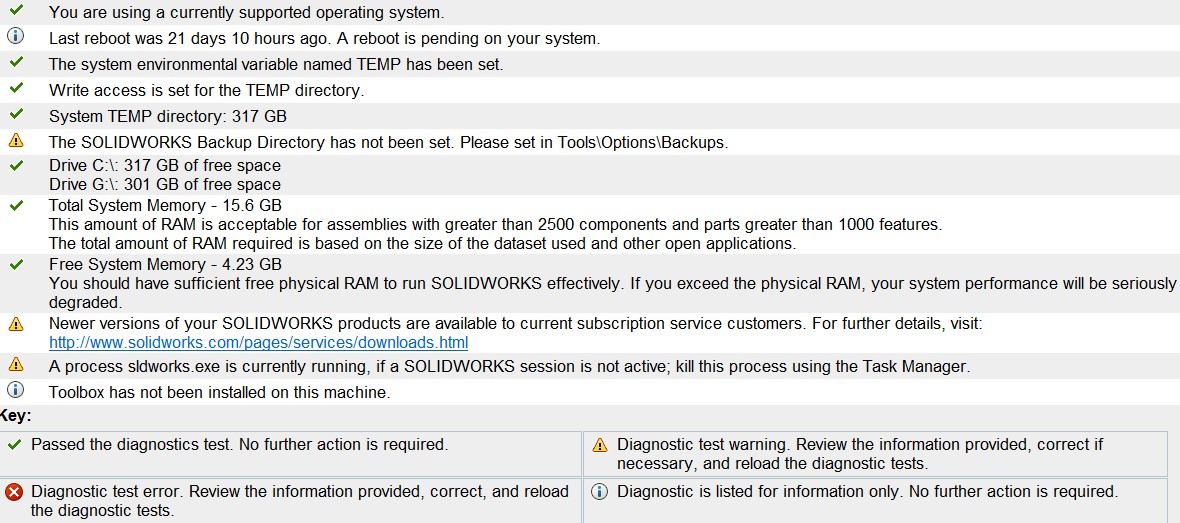
Changing the backup recovery took a moment only because the settings path has changed from Tools\Options\Backups to recovery\Options\Recovery. I also took the opportunity to install the toolbox. Other than that, I see know show-stopping issues at the moment.
I began looking at Solidworks Tutorials to get back into it. The more I read through these topics, the more I realize I will have no problems with Solidworks and won’t need to take a formal course.
I began to select specific topics and watch videos on them. Topics I covered include:
- Design Tree
- cntl-T - Toggle show flat tree display
- Search feature tree
- dynamic reference visualization
- Design Intent - how a part is best created
- preempting which design changes could be made in the future
- when do parameters make sense?
- Make sure Dimensions are line-to-line vs. point-to-point assuming thats the design intent
- Solidworks Modelmania may be a good resource.
- How Solidworks handles multibodies vs. assemblies
- We can start in assembly and build parts out of it. This allows dimensioning parts to one-another.
- be careful when saving. Good practice to save all files via “Save externally (specify path)”
- This workflow will create inplace mates that can be broken
- Another Video on this subject
- Trim Tool
- 3D Sketches
- tip: use 4 view-display
- Modelling from Photographs
- Tools/Sketch Tools/Sketch Picture
- Multibody modeling vs. modeling in-context of assemblies
- possible to insert parts into parts. Hit green check to simply drop on origin.
- right click part, edit in-context to change a part upstream.
- You can derive parts from bodies, and they will remain linked as default
- Save bodies is actually a feature in the tree. Anything to come after, will not propogate.
- Starting in part module, splitting bodies, save bodies, and inserting into assembly; might be an easier workflow than starting in assembly mode.
- Best practices and speed
- Sketches should be fully constrained
- S key for shortcuts. Right click to customize
- model about origin so you don’t have to create midplanes. Hold m key to extrude from midplane
- Advanced mates. Combines multiple mates, much like a joint in F360.
- Copy with mate and hit repeat to copy multiple elements with mates.
- Create folders in tree
- Notice different select options in select menu
- Another video on tips for beginners.
- modifying STLs
- STL imports as graphic file
- Use convert entities - > Intersection curve - > Exact Curve
- shift click when dimensioning circles will allow end-to-end dimensioning
- Convert entities seems to be similar to project feature in Fusion. I imagine its good to be careful with this tool.
- Intro to surface modeling in SW
UV Curing Station
For my first Solidworks project, I wanted to draw a UV curing station for the curing of SLA resin prints. I was designing with laser cutting in mind. I wanted to create something similar to this or this, but perhaps even simpler. Some more good info here.
I attempted to create this lasercut shell of the curing station in the assembly-mode of SW. I was still getting used to the nuances of SW and ran into many rebuild errors. This prompted me noting some of the notes above and watching some of those tutorial videos. My crucial problems that I eventually resolved we’re as follows:
-
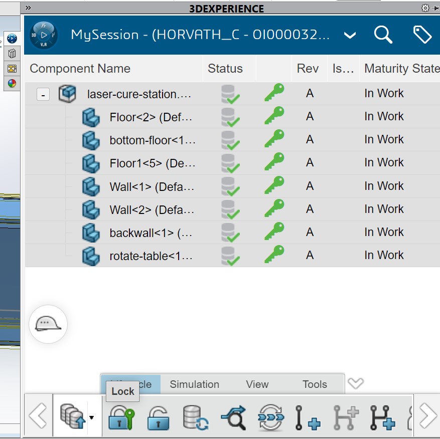
Forgetting to unlock the part when returning to it, which opened it in read-only mode * I later found out this was only an issue when saving projects in the 3Dexperience cloud. I have since been saving everything locally to avoid the permissions issues. * If you are saving to the cloud, you must navigate to this menus and “lock” the files before editing.
-
Adjusting geometry of one part, but not using the timeline bar to go back to when it was created. This left me susceptible to creating circular logic and rebuild errors.
- Changing the name of parts within the model tree, did not seem to update their local part file. This seemed to create duplicate files and mismatched naming
- I tried to use “Global Variables” to drive things such as sheet thickness. This worked at first, but as I began to edit new parts later on, these global variables we’re inaccesible. I suspect I can find a better workflow for creating global variables.
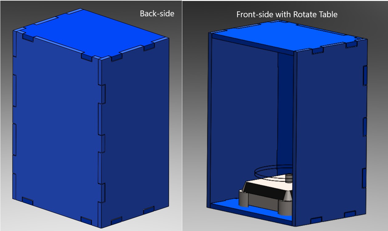
Eventually, I was left with an assembly drawing I was satsified with for now. I will return to this project and refine it for week 03, since it will be relevant to computer controlled cutting found here.
Drawing Something from Photos
As another practice excercise, I wanted to try drawing something a bit more difficult and from reference photos. Looking around, I settled on my 3DCONNEXTION Spacemouse Pro. Downloading 3 views from the website, all I was missing was a good orthogonal side-view picture, which I was able to take myself. I followed this guide for importing the pictures into a SW design space. Interesting side note, I was actually using my spacemouse to navigate views while trying to draw the spacemouse. Meta?
I started adding images to the different views, being careful to scale the images to the appropriate size by using a construction line as reference.
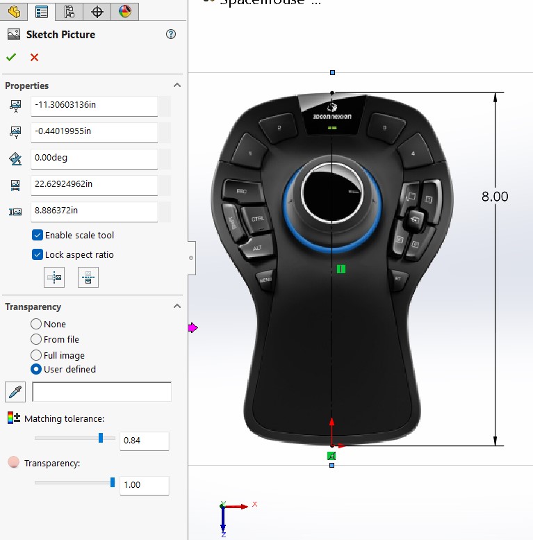
Using this method, I was able to put 3 to-scale reference images into 3 different planes. I will use these to base my geometry off of.
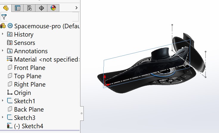
I then went about tracing the different views and creating features accordingly. This overall shape offered very good practice with the spline tool, which will come in handy once I turn towards surface modeling.
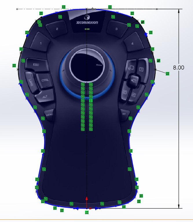
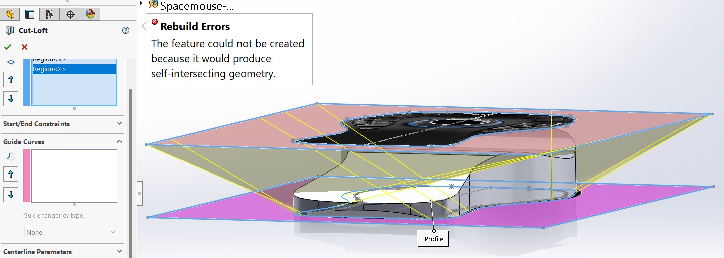
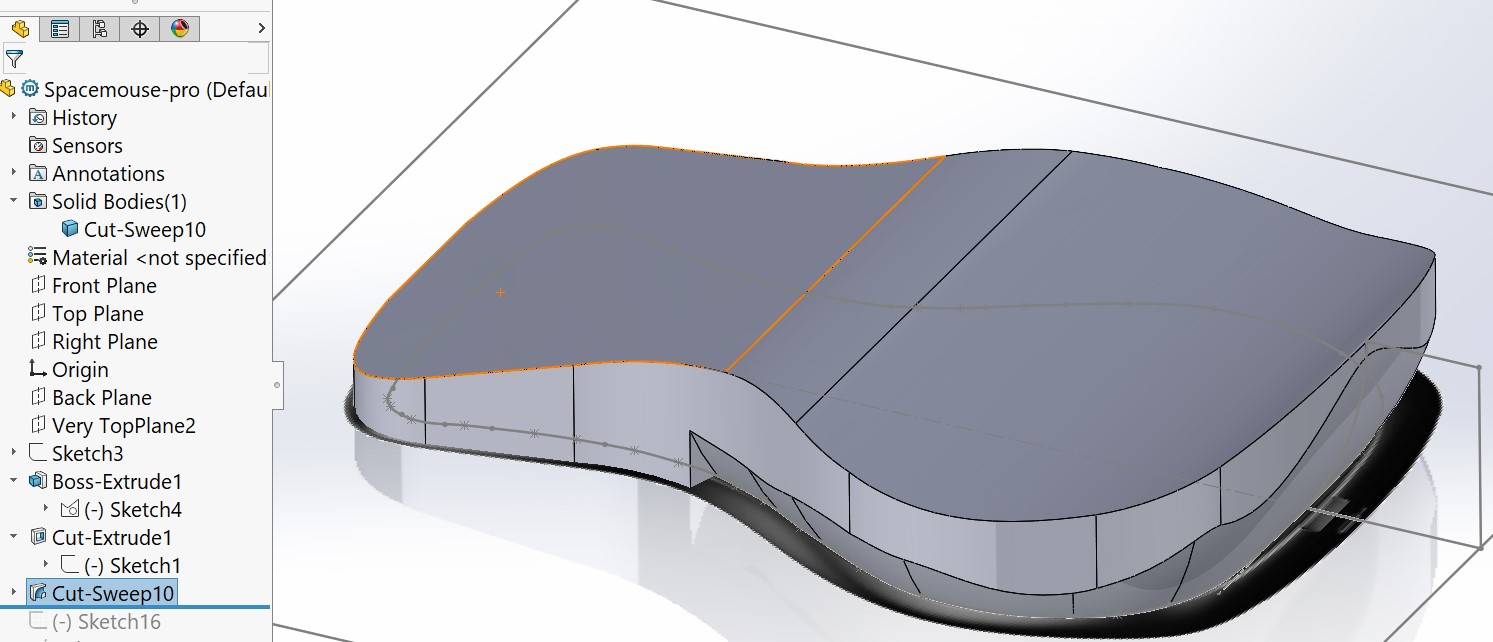
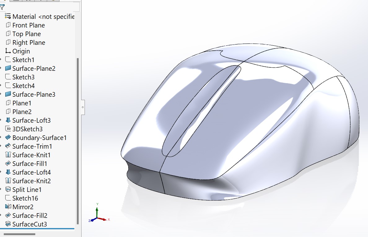
This worked great to create the top and side profiles. However, I had much difficulty creating the curve-inclined profile that surrounds the entire mouse. Upon further inspection, this seems to be a curvilinear profile with varying degrees of curvature, angle, and takeoff weight. Someone who CADs a lot was really showing off. Well I had hoped to get it done with one feature. First attempting a lofted cut between two regions.
Specifically, I tried to draw the widest profile near the top of the mouse, the smallest flat profile near the bottom of the mouse, perimeters around both, and then a lofted cut between the two regions (in pink below). The thought was that I could then add curved guide rails as needed to perfect the loft and draw the mouses’ curved profile. This was a longshot, but in my mind it could work. Unfortunately, in practice SW did not seem to like lofting between two sketches made up of splines. It created a bunch of whacky yellow lines between intersection points, and had rebuild errors before I could even attempt adding guide curves.
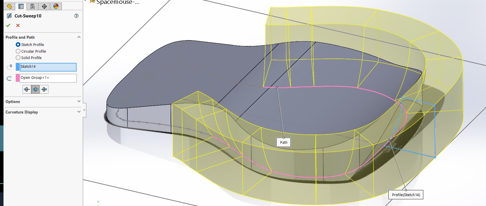
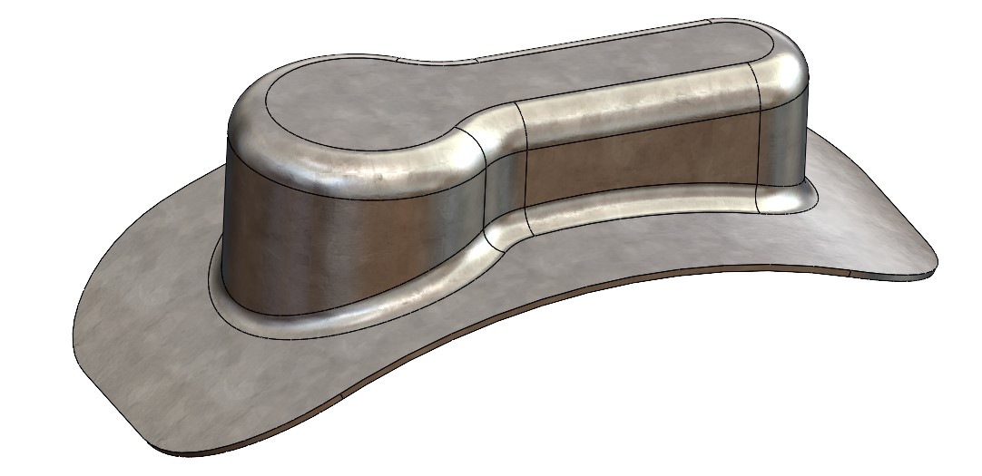
Having given up on the loft feature, I turned my attention to the possibility of a sweep. I knew this wouldn’t create the perfect geometry, but I hoped it would atleast offer me “good-enough” results for the purposes of the excercise. In practice, I found sweep to be quite finicky too. I think the main issue I ran into, is that a sweep does not like to intersect itself, which is very limiting when sweeping around a splined profile with ups and downs. Anyway, I pushed the sweep as far as I could before it created rebuild errors. This was where the top-profile of the mouse began to sweep back outward. This makes sense that it would stop there, because at this point the sweep would begin to intersect itself. See results below.
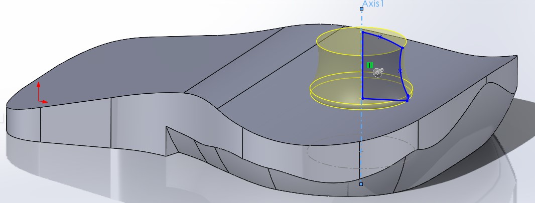
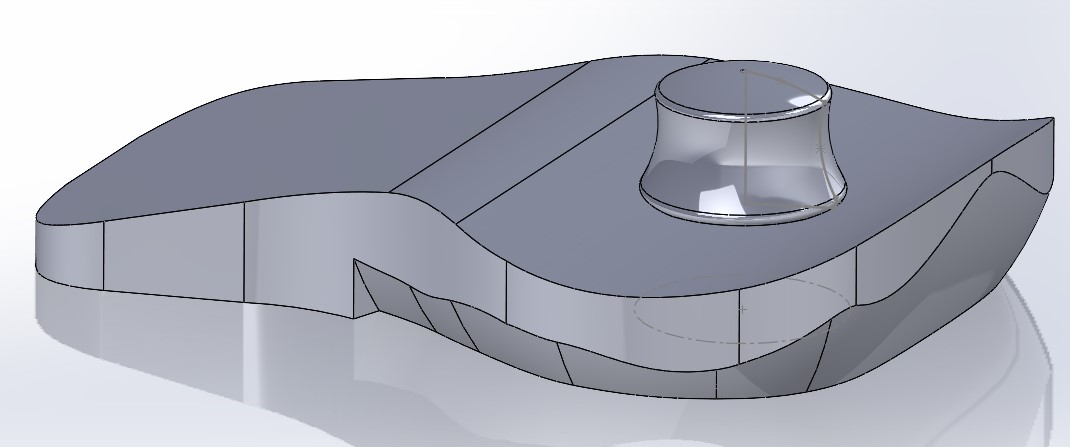
Having spent enough time on this excercise already, I moved on to what I knew would be an easy feature. The control knob. To make this, I created a sketch and a rotation axis based on the position from the side-view picture. From there, I sketched a cross-sectional profile and revolved the shape. Finally, a fillet made for a nice finishing touch.
This is probably as far as I will take this excercise, unless I have a breakthrough Idea of how to better create that outer profile.
I’m wondering if surface tools can help…
Surface Modeling with Solidworks
Back into the tutorials I go. Links and my results below.
-
Getting Started with Surface Modeling in Solidworks
- No issues following here. Results:
- No issues following here. Results:
-
Basics of Solidworks Surface Modeling
- A little trickier here, but no issues once I understood the goal of what we’re trying to do. Results:
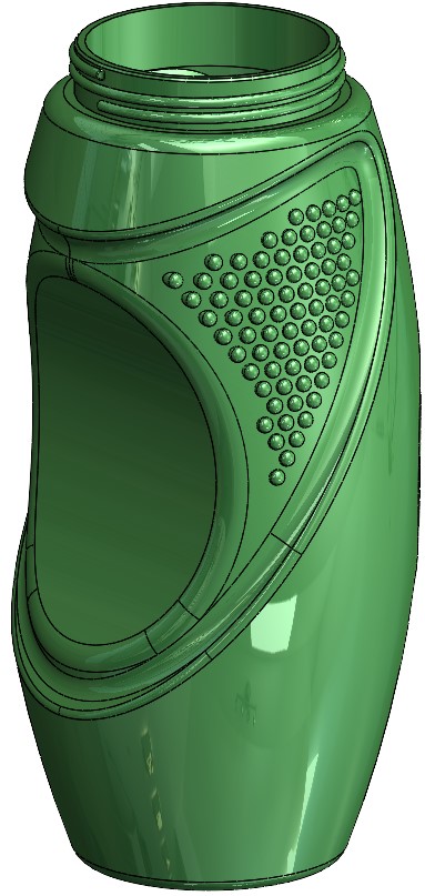
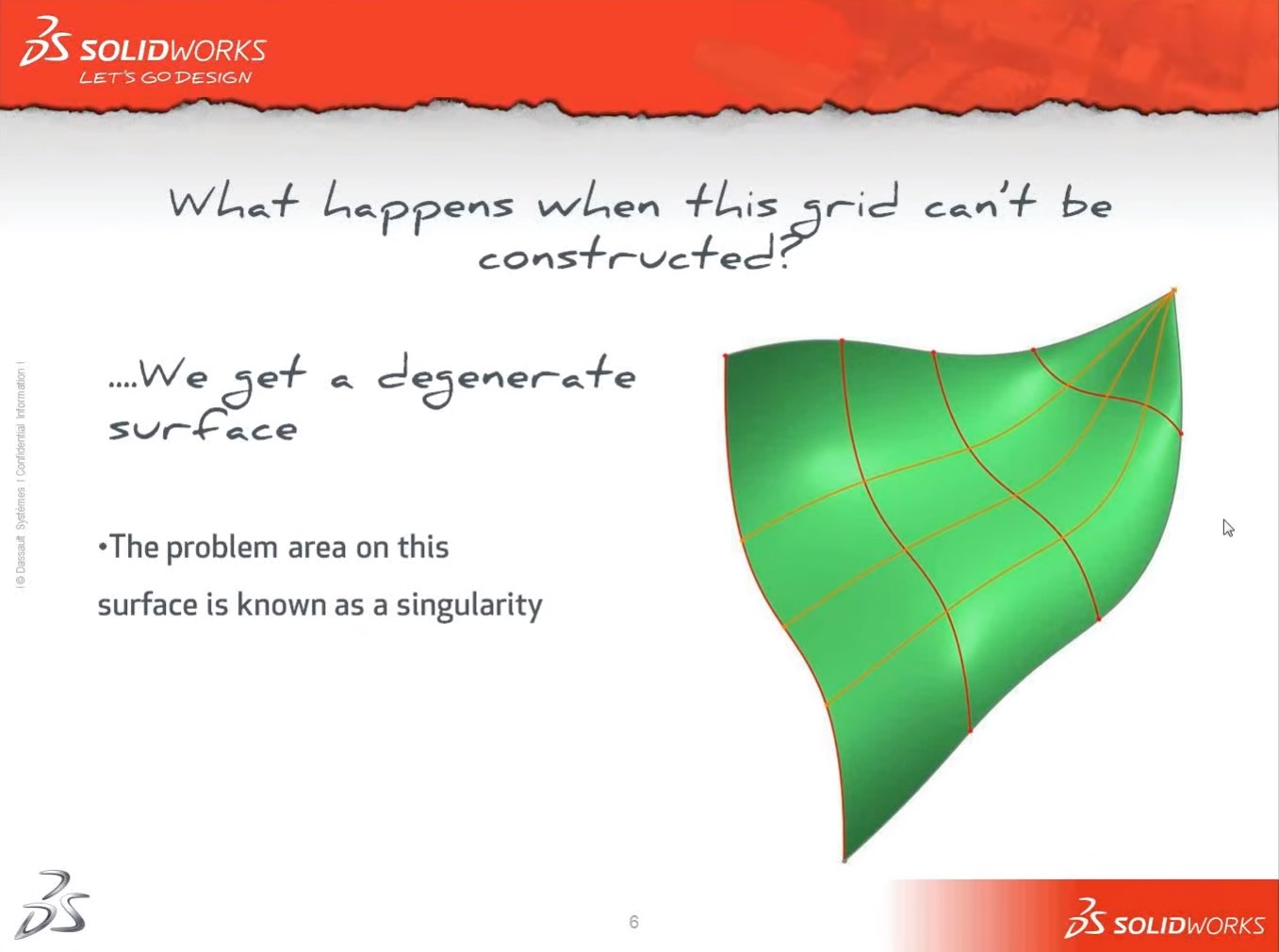
- Introduction to Surface Modelling in SolidWorks
* Beware of 3 sided surfaces because these can create a singularity. This can be resolved with the trim tool to make 3 sided sections into 4.
* 3 types of continuity (c0: contact, c1: tangent, c2: curvature). More details below.
This 3rd tutorial is the best tutorial I’ve taken so far. Whereas other teachers tend to only describe the operations and mechanics, he was explaining his design intent each step of the way. I will look for more from them.
My model was largely succesful, however I had an issue whereby it would not combine solids near the end when I tried to mirror them. So in affect, the model pictured below is actually two models touching (or slightly overlapping?) on the midplane. If I had to guess, I would think it was having issues with overlapping geometry and boundary conditions such as curvature.
After taking these tutorials, I am more than sure that surface tools can help me finish up the spacemouse model. I will return to this project if I have time.
Modeling potential final project
Speaking of time, it was time to turn to the assignment for the week.
model (raster, vector, 2D, 3D, render, animate, simulate, …) a possible final project, compress your images and videos, and post a description with your design files on your class page
2D Concept Sketches in Concepts App
I began by creating a few more concept sketches in the Concepts 2D sketching app.
The Concepts app has some very useful features that I am beginning to fall in love with. * Cross platform support for tablets, phone and 2-in-1’s. * I am drawing on my Asus Zenbook Flip 15 (528EH) * Stylus friendly. * Drawing with a surface pin * Unlimited layers with the paid version. * Creates vector images * Canvas and zoom function are infinite. Love being able to zoom way in on fine features and detail them. * Having access to copy/paste instantly gives this app a huge leg up on my old sketching medium, pen/paper.
The goal at this stage was to produce a reference image to trace in a 3D CAD app. So I got a little trigger happy with the Copy/Paste commands, and produced many sketches in short order. Most of them are downright awful, but this workflow made it easy to fail-fast and continue on.
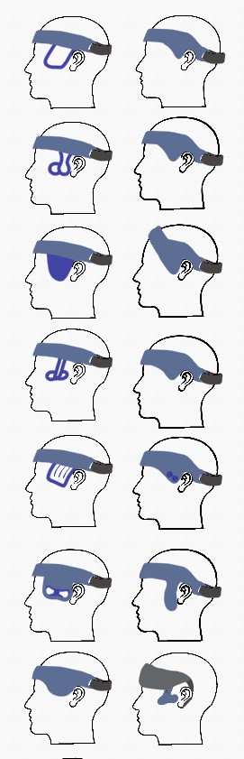
I settled on this one to try and draw in 3D.
Since this project is in such early phases and highly conceptual, it was important I keep my goals in check (see list at top of page).
Moving to 3D and Solidworks
Next order of business, was to find a suitable reference model of a human head. After a quick google search, I found the repository “SketchFab” and made a free account. I found a collection called ref_human, with tons of 3D scans and models of human heads. I wanted one without much hair, so I could design to the human head itself. Otherwise, I would’ve started with Bill Murray. Therefore, this .STL model of Dwayne Johnson (attribution below) seemed like a good starting point.
Naturally, this mesh file was very high resolution and unweildy to work with from a resources standpoint. I attempted to reduce the # of triangles using the “Decimate Mesh Body” feature in the mesh modeling tab. Even after removing 75% of triangles, the maximum deviation from the shape was 10 microns. I think this will be sufficient for my reference model needs, so I ran the reduction by 75% again, for a total max deviation of 50 micron. the model already rotates noticibly smoother and should be easier to work with. And seconds after typing that, SW crashed… Starting again from scratch, I will run the simplification in one go, simplifying by 95% with a calculated max deviation of 40 micron, being sure to hit save once its done.
The next step was to scale and orient the model to my planes and scale it to human-scale. For this scale, I took a measurements of my own head (143.5 mm) and Dwayne’s head (23.3 mm) from temple-to-temple, and uniformly scaled Dwayne’s head up by 6.14 (143.5/23.3) using the Scale mesh function accordingly.
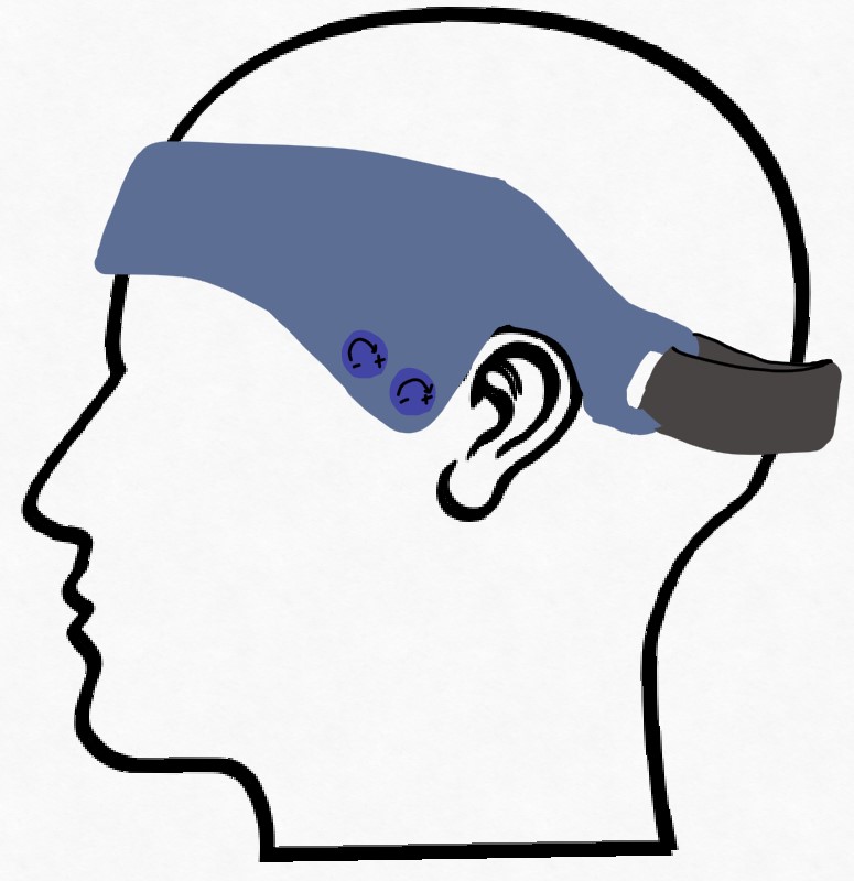
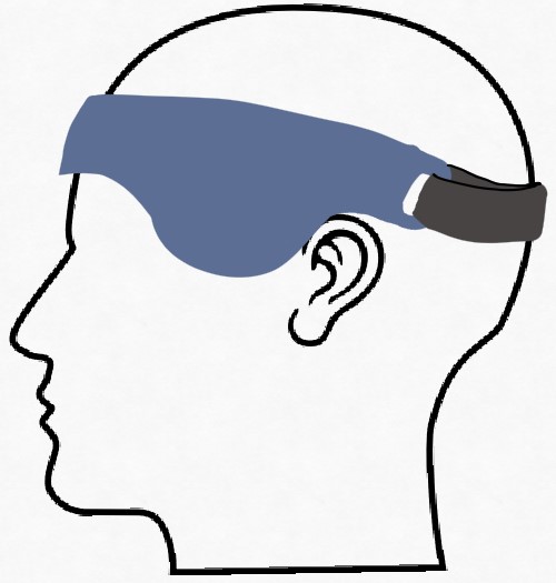
I then created a sketch plane on the right plane to add my reference image. I removed the white background and made Dwayne’s model transparent so I could compare the two. You will see that apart from a few notable features such as ear position, these two reference files mapped to one another quite nicely.
It wasn’t until I layed the files out in this manner, that I realized this concept might dig into the user’s ear as you tighten the strap. This was reason enough for me to revert to an older concept that doesn’t hook the ear so much. This one still looks like it could have the same issue, but I will simply design it such that the device clears the front of the ear by a good margin, unlike I’ve drawn it in the concept.
I started by tracing this cross-section into the midplane. I know eventually, I will need to draw a 3D sketch in order to create this 3D shape, but I wanted to start simpler. Once traced, I created a planar surface using the sketch as my bounding entity. I then wanted to remove the section that was piercing through Dwayne’s skull. I did so by creating another sketch in the midplane that traced his forhead, and then using the trim surface command. In hindsight, this surface was never actually used, but I used the original sketch extensively.
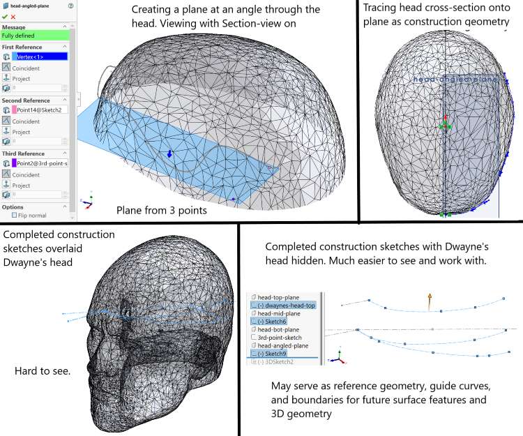
Next, I wanted to trace Dwayne’s head into more usuable sketches. This would be useful since mesh files are unwieldy to use and look at. I started by creating some reference planes to trace the shape of the head onto. Two of these we’re parallel to the top-plane. One at the top of the existing surface and the other at the bottom. Then I realized the device is drawn at an angle, so it would be useful to trace the head at that angle. So I had to create a third plane that referenced two points on that first sketch and a third point that insured the plane would still be normal to the midplane. This took some finagling to create that third point, but I was able to get it done by creating another reference plane and sketch. This left more trash laying around then I would normally prefer, but it was needed to get the angled plane created. The rest of this tracing process is detailed in the image below.
I then took my sketch from the angled plane and extruded the surface. Once there, I was able to project my original sketch onto it as a split line. This allowed me to delete the portions of the face I did not want using delete face. Note, I did find that I had to project my lines one at a time. I got errors when attempting to project the whole sketch at once. Using offset surface allowed me to create an inside surface and outside surface of the model with 6 mm in between.
I then wanted to conencted the two surfaces using a sweep. However, I found that in practice, sweep caused issues later on because it did not accurately follow both side surfaces. This overlapping geometry caused me issues when trying to create a solid from the surface. Replacing this sweep with a loft, and using both side edges as guide rails resolved this issue. The unfortunate part of using a loft, is that you need profile geometry at the begininng and the end of the rails. So I had to draw a sketch at the end of the rails and made it match the first profile. With this workflow, changing the profile shape would require changing two sketches, which is not ideal. In the future, I could find a way to tie them together such as using global variables.
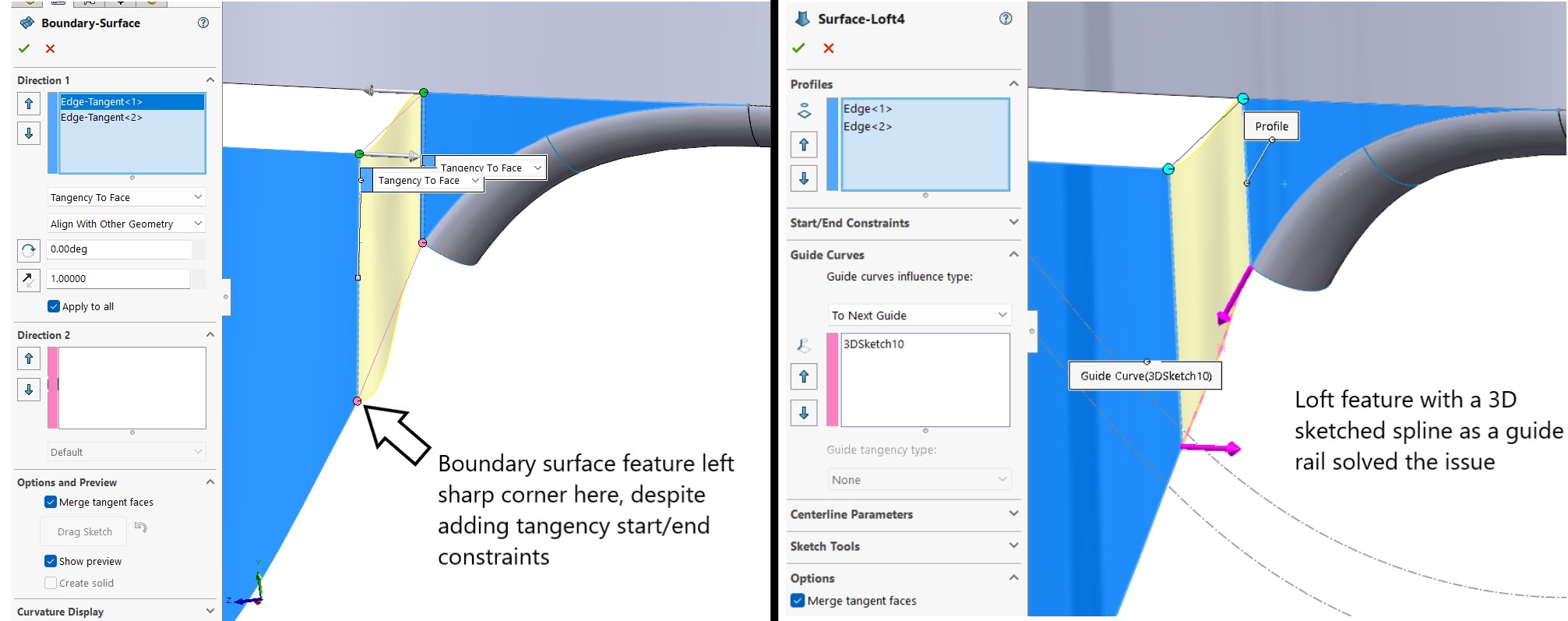
I wanted the low-hanging arc further offset to allow room for the cheek bones. I repeated the process of splitting this surface off using sketches, split lines and offset face. I also made this face smaller so that it could reconnect with smooth surfaces. This process gave me little issue, but reconnecting it to the main surface proved tricky. I first attempted this with a boundary surface, which worked for one side of the model, but but I was getting unsuitable results on the lower left edge. Despite adding tangency start/end constraints, I was getting a sharp corner. I decided to instead try 3D sketching a spline to act as a guide rail for a lofted feature. This eventually worked once I realized how to control the 3D sketch. I would caution against using this method, because any changes upstream to any of these features, and this lofted surface would break.
The rest of these surfaces were easily joined via surface fill features. A similar process was done on a surface that was offset to create the inner wall of the headset. Then these two surfaces connected via a boundary fill feature, with curvature start/end constraints. Since this created an arc that was different to the main sweeps, rejoining these final two gaps could only be done with loft features.
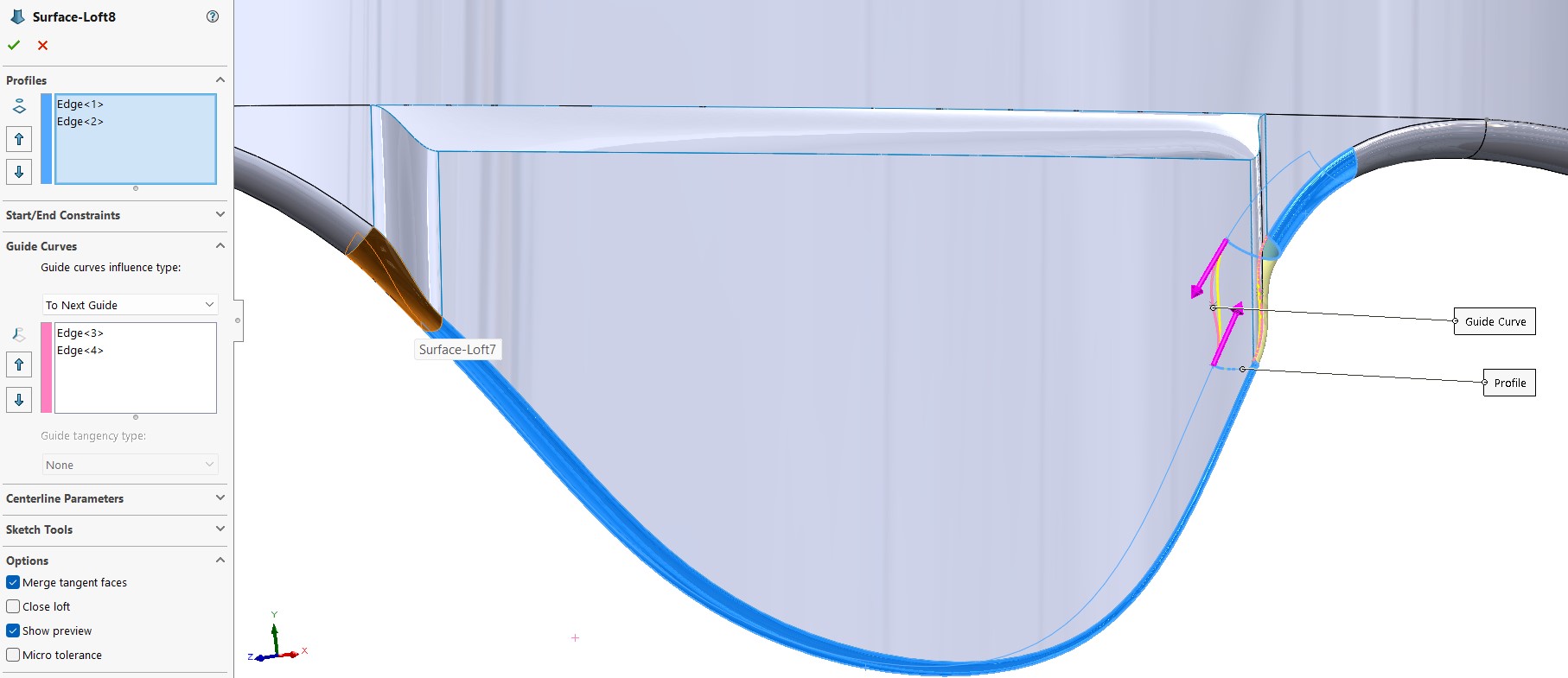
The orange surface shows the first loft (already completed) while the yellow shows an in-process feature. While not the prettiest join in the world, I quite like the end result here. It really shows the power of surface modeling to handle complicated geometries.
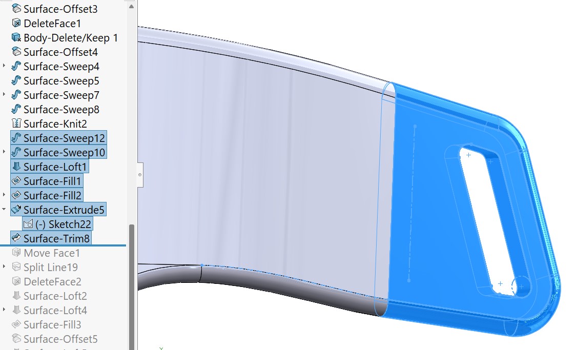
This back hook was easily created using a combination of a 3D sketch, swept surface, an extruded surface, and a surface trim. Noting the one issue was that the sweep left another small gap near the end. Once noticed, this gap was easily filled with another loft. I believe this gap was one of the main issues preventing me from creating a solid at the end.
Finally, it came time to either thicken or create a solid from the surface. As previously mentioned, this step gave me many issues. I found small gaps between some of my surfaces and other surfaces overlapping. The knitting command was helpful for relieving the really small gaps, but structural changes we’re needed to resolve some of these issues. The most frustrating thing about surface modeling seems to be that any changes near the top of the feature tree, do not propogate well. So any small change, and you are often fixing bugs for 30 minutes or more. This is a problem I see with Solidworks more generally. It is unforgiving on this front. Perhaps some looking into some best practices could help alleviate some of this pain.
Eventually, I got “create solid” to work whereas thicken still seems to cause issues. I then mirrored and combined my new solid to make the headset symmetrical. I imagine the issues with thicken are due to some of the complex geometry. This theory was validated after I attempted to take the solid and hollow it out via the shell feature. I got the following error.
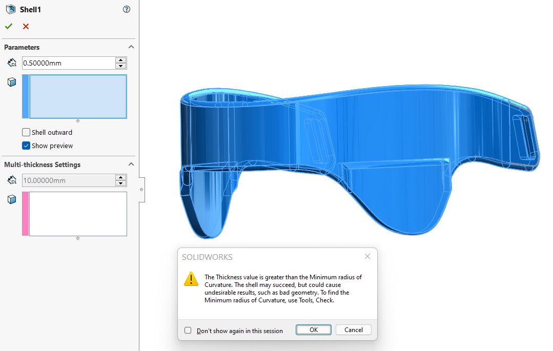
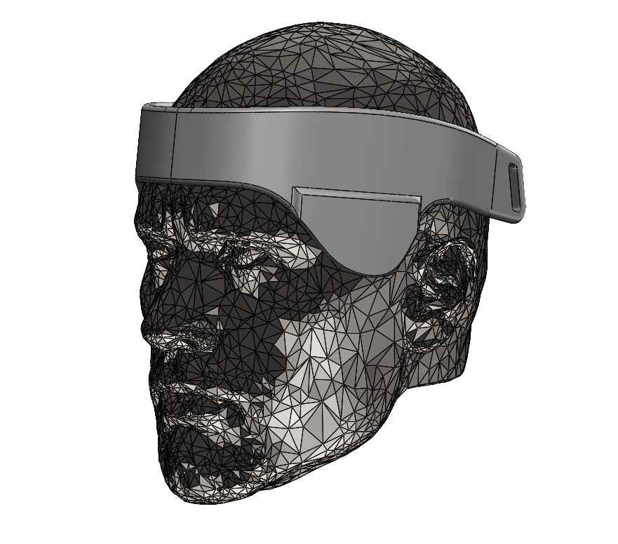
This erros is more than likely very similar to why the “thicken” from surface command did not work. Even still, the program did its best to shell the solid. Checking the part with split-view offered a cool view into the completed part.
And of course, a hero shot ft. Dwayne “The Rock” Johnson.
Learning 2D drawing in CorelDraw
I set out to learn CorelDraw specifically for computer controlled cutting. More information on that can be found here.
Algorithmic Design using CadQuery
For my 3D printing week, I am hoping to use both algorithmic and generative design in order to push my CAD capabilities. I am hoping to use CadQuery and Fusion 360 respectively. Installation of CadQuery is documented in week 1.5, found here. And I will document my tutorials and learning of both CadQuery and Fusion Generative Design here.
Learning CadQuery
I followed along the first CadQuery tutorial here. The only issues I ran into were syntax related. Once completed, I began playing with the parameters and basing them off of eachother. E.g
H = 40
W = 1.5*H
This worked of course, but still felt like parametric design. Neil’s words from the recitation about the power of algorithmic design still ringing in my ears, I decided to create a quick loop to export several iterations of the same model with one variable varied. This code can be found in my repo here. A quick google refresher of some python syntax.... Success!!

I then proceeded to run through many of the standard examples here, which are hard to get wrong since its mostly copying/pasting code. Even still, I was learning. Then I decided to make my own example, that would be more relevant to my upcoming Fab Dice Project, documented here. I wanted to make a simple sign that said Hello World. After reading through the CADquery documentation, I found two relevant commands. makeText would allow me to create 3D text whereas Compound would allow me to combine or cut another object with that text. Therefore, I was able to make the entire sign with just 5 lines of code.
import cadquery as cq

result = cq.Workplane('XY').rect(6,2).extrude(0.25)
text = cq.Compound.makeText("Hello World", 1, 1, font='Arial', fontPath=None, kind='regular', halign='center', valign='center')#
result = result.cut(text)

show_object(result)
This code can also be found in my repo here. At this point, I was impressed. An entire world of possibilities of algorithmic design flashed before my eyes. I then turned my attention to the afformentioned Fab Dice project, for my week 5 assignment.
Algorithmic Design of Fab Dice
DND dice come in 5 shapes: * Tetrahedron * Hexahedron (Cube) * Octahedron * Dodecahedron * Icosahedron
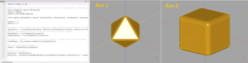
I found that my easiest route to make these shapes would be to import the function cqmore, documented here. I found the hard way, the best way to do this is the 2nd method they recommend, using the following code.
## Ensures that I can still use base functions of cq Workplane(). Otherwise, you can overwrite it completely with cqmore's version of Workplane

from cadquery import Workplane
import cqmore
cqmore.extend(Workplane)
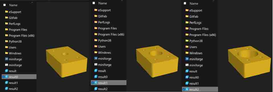
This extension allows me to easily make polyhedron shapes! I was able to create a script to generate a random version of the 5 platonic solids using the following code,
radius = 1
detail = 0

#Creates a dictionary with the different shape functions and number of sides
ShapeDict = {tetrahedron(radius, detail):4,hexahedron(radius, detail):6,octahedron(radius, detail):8, octahedron(radius, detail):12, octahedron(radius, detail):20}

#Split dictionary into two lists for the keys and the values for later on
ShapeKeys = list(ShapeDict.keys())
ShapeValues = list(ShapeDict.values())

#returns a value 0, 1, 2, 3, or 4 for calling a shape from the dictionary
randShape = np.random.randint(len(ShapeDict))

#assigns the random shape
shape = ShapeKeys[randShape]

#Create the object
platonic = Workplane()
platonic = platonic.add(Workplane().polyhedron(*shape).translate((2 * radius * detail, 0, 0))).shell(-.1).edges().fillet(0.1)
I was able to generate these results.
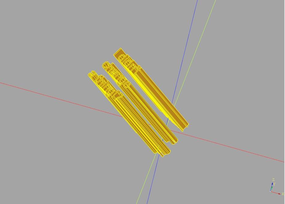
Then I moved on to generate the text on the sides of the dice. Unfortunately, I had trouble using any of the face selector commands which would’ve made this much easier. My initial hope was to simply select the faces one by one and loop through them in a way that could be generalized to any of the platonic shapes. In practice, I found that the Faces() selector() commands did not offer an easy path to selecting these faces one by one, especially when they were nonplanar to the original origin planes. Additionally, I found no easy way to create a workplane on the center of these faces, even with many attempts. So I was stuck hardcoding the text. I used loops where I could, but the code was now far from pretty. Even still, I was seeing the power of algorithmic design because with a little more documentation available and a little more time, I’m sure I could have gotten my genralized elegant solution to work for any shape.
Below are the results of my first attempt at hardcoding the text.
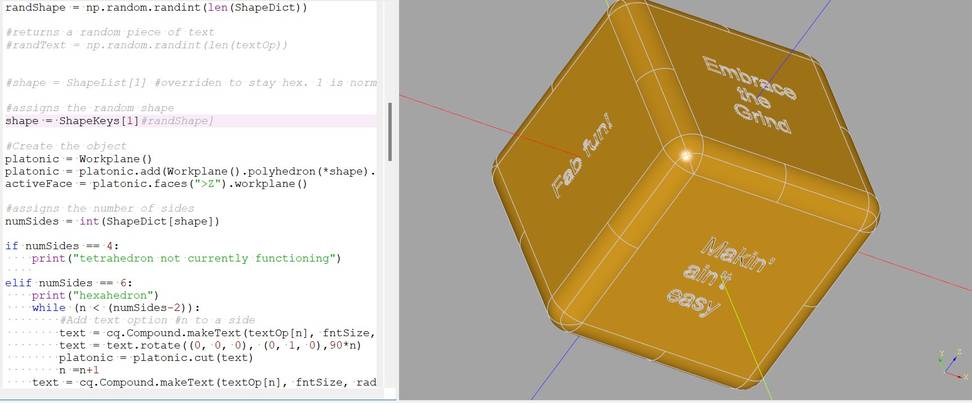
As you can see, I am essentially extruding the text from the origin, rotating it normal to the faces, and cutting the object by the text. I’m sure I could’ve come up with a more elegant solution for these vector and rotate commands that involved variables, loops, etc. but again… time!!
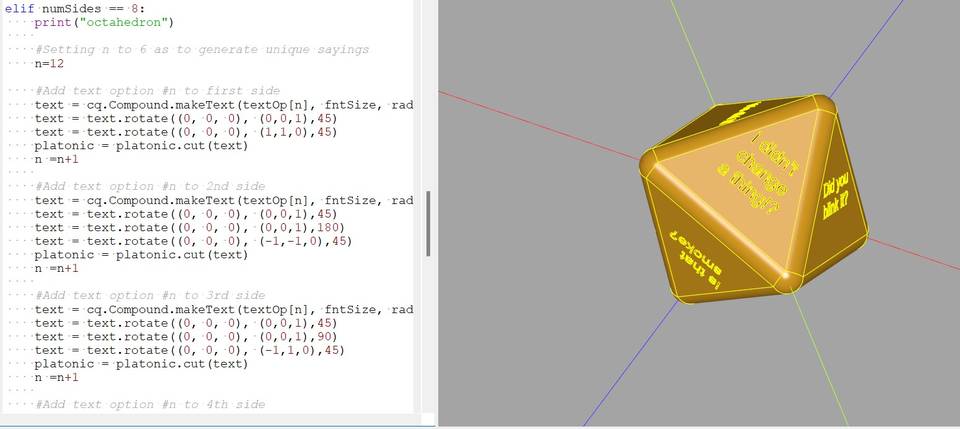
I then worked on getting these items to the right scale by setting my radius variable to 8 mm, my fillet variable to 1 mm, and my shell variable to -1.5 (wall thickness). Online, I found a recommended minimum wall thickness of 2 mm, which seems quite thick for an object like this. So I decided to start with 1.5 mm and see how it did.
Generative Design of Fab Dice Tower
Preparing model
First I set about finding a suitable dice-tower from the community to modify. I had a few parameters,
- No support needed
- Simple castle shape, no flair
- Fits on my resin build-plate
- ~3D solid model available~
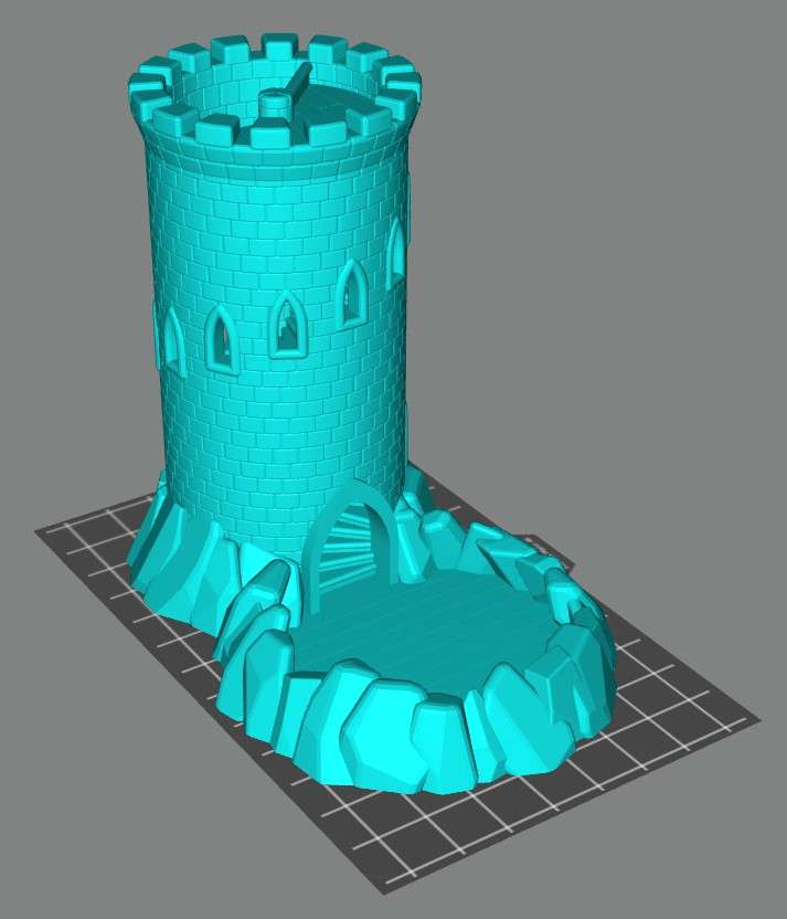
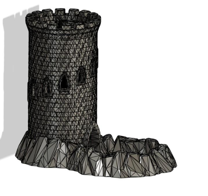
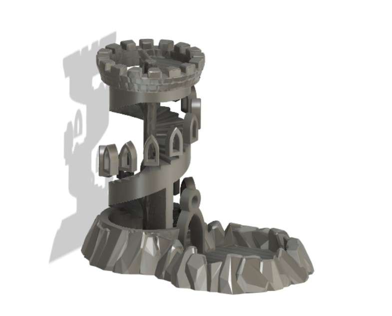
I quickly realized that most dice towers came in multiple pieces and would be far too large to fit on my photon 4k build-plate. That said, I followed a remix-rabbit-hole and found what seems to be the perfect option. This mini dice tower from thingiverse user gaffneyswrath seems to fit the bill (and the plate) perfectly. See below,
The only trouble is that per usual on thingiverse, they only uploaded the .stl file. So I will need to convert it to a solid body before I can modify it. The good news is that I’ll get to try out Fusion’s newer tools for converting a mesh to a body. Upon trying this, I ran into a series of warnings and errors.
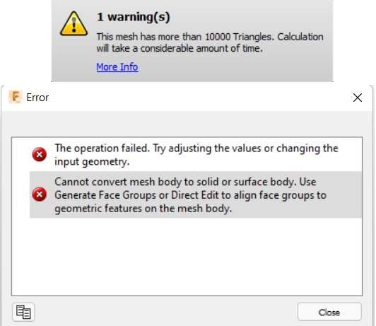
So I first tried reducing the # of facets from some 300k to 30k. Then I ran into the error seen above, and followed the instructions to convert it into face groups. It was able to convert it into 128 face groups. Then I reattempted the conversion and let Fusion think for awhile… and it came back with this monstrosity!
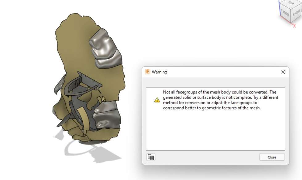
No, no, no Fusion. We’re not even to the generative design yet. It’s not supposed to be this ugly… yet! then attempted to reduce the # of face groups and try again, same results! Next, I gave up on trying to make the prismatic conversion and tried a “faceted” conversion. Less ideal, because it will make every single triangle surface on the mesh into a triangle surface on the solid body… a good way to make a laptop cry. This was the result I often got with the “old” conversion method in fusion 360. It seems the new parametric conversion option may be reserved for simpler objects.
Whatever the case, it looks like it did ok and my computer isn’t chugging too bad. Glad I did the facet reduction earlier.
Now the tricky step of removing the walls (which will be replaced by generative design, while leaving behind the staircase and perhaps even the windows/door if possible. The faceted nature of the model will make this already difficult process all the more fun. I decided the easiest way would be to replicate the windows/door as solid bodys and delete the existing walls/window/door entirely. Long story short, this was hard… but we’re ready for generative.
Let’s see what you can do Generative.
Exploring Generative Design
The generative module seemed mostly self-explanatory. Even still, I read through this awesome tutorial which gave me even more confidence.
Earlier I had added a whole to hold up the eyeglass above where the dice land. This would be one of the forces that would be useful to input into the simulation so I took some time to roughly caculate the bearing load on that hole.
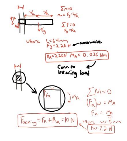
I settled on 10 Newtons. Along with gravity, these would be the only forces that the simulation would be concerned with. It also made me constrain the base of the tower before I could run the generation.
As far as material to simulate, I did my best. Since most are not engineering materials, there is not good data available on the material properties of printing resins. This is further complicated by the anisotropic nature of 3D printed parts. Therefore, I have erred on the side of caution and attempted to input which data is available into a custom material in the Fusion material library.
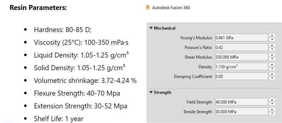
Luckily, the program is smart enough to ask you which manufacturing technique’s to design for and also in which orientation. I selected additive along the -Y axis.
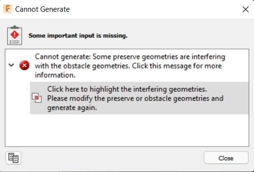
Lastly, I had to work through some errors such as preserve geometry colliding with obstacle geometry. This was easily resolved but I wish that the program could ignore these specific collisions.
Here is the setup and results for my first attempt.
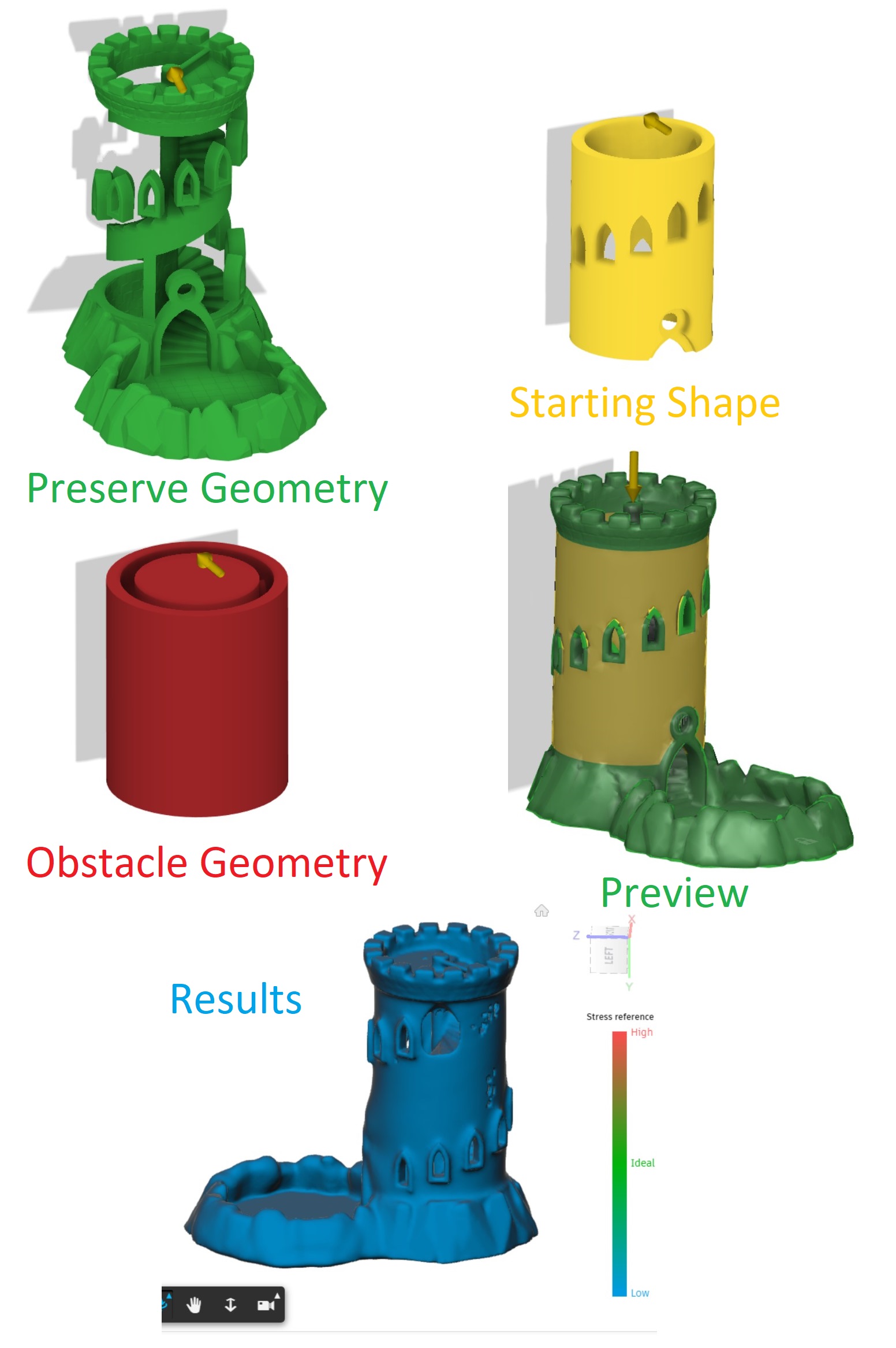
These results were underwhelming. But they do go to show that the preview can be trusted to an extent, because the final output, which costs ‘cloud credits’, came out looking much like the preview after hours of server-side computation. Before running another generation, I will make sure I like the look of the preview.
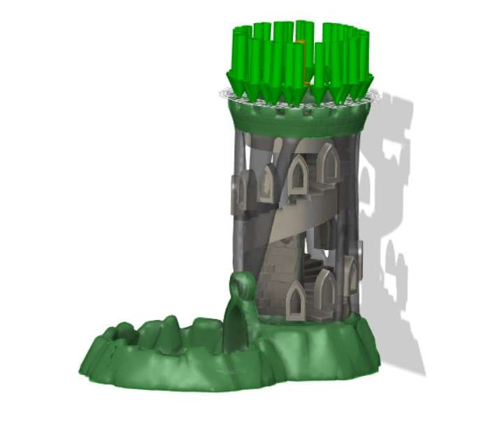
Next, I tried making some big changes. I separated the top and bottom of the castle into different components. In the name of erring on the safe side, I removed the central staircase from the generation, so that the walls would be generated as if they were the only portion of the model holding up the castle top. I will later remerge everything together once I am satisfied with the walls. I removed the floating windows out of preserve geometry, because this seemed to be keeping the generation from removing much material. Additionally, I created obstacle geometry within the windows and the doorway, to keep these areas free and open. It seemed like the default number of windows was too many to get a good generation going, so I have reduced the number of windows by half. Additionally, the model seemed overly biased towards the bearing load on the front side, so I decided to add some forces to the top of the model. This would be a good simulation of a foreseeable scenario of someone accidentally placing something on top of the castle or drop it on its head. Looking at the preview, we’re starting to get somewhere.
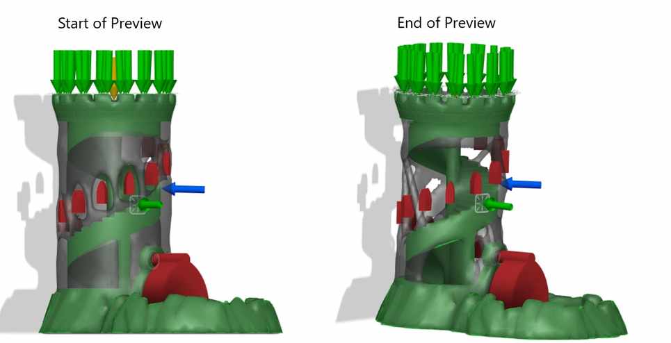
However, I’ve just noticed a potential issue. The stair-case may become unprintable geometry if the outer wall is disconnected from it. So I added the staircase back as preserve geometry, but still left out the window frames as preserve geometry. Additionally, I added a pressure force to all sides of the spiral staircase, and this really seemed to do the trick. Now the structure began to create the sort of look and performance I was going for. Not only did it look cool, but this structure should be able to withstand reasonable forces from almost any side. In other words, its not overly biased towards just a few forces.
Ironically, the very start of the preview mode was close to the geometry I would like to see, but as the iterations go on and the geometry becomes more optimized, the gaps become too large. I am worried about dice coming out of the side of the tower, and I am having trouble translating that constraint into the design. There should be an option to say “largest gap size”, but I’m having trouble finding it.
And here were the results from hitting generate,
So the program actually allows you to choose from the different iterations after-all, which is awesome! Truly, I wish there was a version between iterations 3 and 5 that had a little more material removed but with still enough wall to keep the dice contained. Next, time permitting, I will try to merge my favorite aspects of iteration 3 and 5 before hitting print.
Last note, it is striking how much of an effect the “starting geometry” has on the geometry. This closely aligns with my loose understanding of machine learning. Boundary conditions and starting conditions very much affect results and the space of possibilities. Cool to see in action.
- Surface modeling will always be more time consuming. Use it sparingly and only where needed
- Despite the long process, my headset still turned out looking more flat than I’d like. I believe I was using surface tools much how I would use normal solid tools. For instance, my first extruded surface led to much of this “flatness”
- Curvature (co,c1, & c2) is very important in surface modeling and deserves further study.
- Some of the tutorials went back and forth between surfaces and solids often. Playing to the strengths of each. Perhaps this would be a better workflow than creating such a complicated shape completely from surfaces, then converting.
- Also be sure to select a vector or raster program at the appropriate time. More generally, always pick the right tool.
- Importing 2D canvas’ into 3D space to trace off of is a useful workflow, especially for surface modeling
- Concepts app is awesome. Will be using it going forward.
- Copy/Paste to fail-fast!
- CorelDraw also seems powerful. Need to spend more time with it.
- Object manager in Corel is extremely useful
- Do not try to edit bitmaps in Corel. You’re gonna have a bad time.
- Hypothetically, something drawn in Concepts could be loaded directly into corel to be traced/cut.
- Fusion allows you to choose from any of the iterations, not just the final.
- Starting conditions matter greatly for generative design
- Generative Design can over-optimize results. Be careful what you ask it to do.
- Trust Fusion 360’s preview for generative design as a rough attempt.
Note: All design files and images can be accessed in my git repository found here.
All works shared on this site 'A Fab Academy Journey with Charlie Horvath' by Charles W. Horvath are licensed under Attribution-NonCommercial-ShareAlike 4.0 International![]()
![]()
![]()
![]()